Table of Contents
Advertisement
Quick Links
INSTRUCTIONS
®
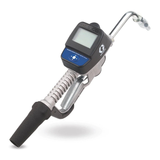
Matrix
Meter
- For dispensing oils and antifreeze over wireless communication with a Matrix system -
Maximum Working Pressure: 1500 psi (10 MPa, 103 bar)
Maximum Flow Rate:14 gpm (53.0 lpm)
Important Safety Instructions
Read all warnings and instructions in this
manual. Save these instructions.
Models:
All meters are preset to Quarts in the Graco factory.
Matrix Name
Model No.
Matrix 5
256282
Matrix 5
256482
Matrix 5
256483
Matrix 5
256484
Matrix 5
256485
Matrix 15
256486
Matrix 15
256487
Matrix 15
256488
Matrix 15
257120
*Extensions and Nozzles must be purchases separately.
5 & Matrix
Swivel
Extension*
1/2" npt(f)
Rigid
1/2" npt(f)
Flexible
1/2" npt(f)
Gear Lube
1/2" npt(f)
Rigid
1/2" npt(f)
Flexible
1/2" npt(f)
Rigid
1/2" npt(f)
Flexible
3/4" npt(f)
Rigid
3/4" npt(f)
Flexible
®
15
NOTICE
This dispense valve is designed to dispense
petroleum-based lubricants and antifreeze only.
Do not dispense windshield washer solvent with
this dispense valve.
Matrix 5 and Matrix 15 contain an RF devise with the
following approval:
FCC ID: TFB-FREESTAR
IC: 5969A-FREESTAR
Quick Close Nozzle*
Standard, Automatic, Non-drip
Standard, Automatic, Non-drip
Standard
Standard
Standard
High Flow
High Flow
High Flow
High Flow
313046A
Fluid
Oil
Oil
Gear Lube
Antifreeze
Antifreeze
Oil
Oil
Oil
Oil
Advertisement
Table of Contents

Related Manuals for Graco 256282


Summary of Contents for Graco 256282
- Page 1 Matrix 5 and Matrix 15 contain an RF devise with the following approval: FCC ID: TFB-FREESTAR IC: 5969A-FREESTAR Models: All meters are preset to Quarts in the Graco factory. Matrix Name Model No. Swivel Extension* Quick Close Nozzle*...
- Page 2 Warnings Warnings The following warnings are for the setup, use, grounding, maintenance, and repair of this equipment. The exclama- tion point symbol alerts you to a general warning and the hazard symbol refers to procedure-specific risk. Refer back to these warnings. Additional, product-specific warnings may be found throughout the body of this manual where applicable.
- Page 3 Warnings WARNING FIRE AND EXPLOSION HAZARD When flammable fluids are present in the work area, such as gasoline and windshield wiper fluid, be aware that flammable fumes can ignite or explode. To help prevent fire and explosion: • Use equipment only in well ventilated area. •...
-
Page 4: Meter Overview
Meter Overview Meter Overview Navigation and Modes Meter Display Adjusting Screen Contrast using ARROWS On the Main Utility Setup Screen (page 5), use the LEFT and RIGHT ARROWS to adjust the screen contrast. • Darken the Screen: Press the RIGHT ARROW multiple times. -
Page 5: Registering The Meter
Registering the Meter Registering the Meter Graco recommends registering the meter prior to If this has not been done first, the software will display installation. an error when attempting to set up meter. NOTE: Before registering the meter, use the Matrix PC Main Utility Setup Screens (F . - Page 6 Registering the Meter REGISTER Screen D. WRENCH Icon: Returns user to Main Utility Screen. Use the LEFT or RIGHT ARROWS to move the cursor over the WRENCH Icon on the display. Then press REGISTER center, ENTER button on meter’s keypad, to confirm the selection.
- Page 7 Registering the Meter e. The meter resets and returns to it’s initial screen. NOTE: If the meter is not able to communicate with the PC during registration, the message NO SIGNAL or NO PC SIGNAL appears on the meter display. NO SIGNAL message means: •...
- Page 8 RF Test RF Test 4. Use RIGHT ARROW to move cursor over START . 7). An RF Test is performed before a Matrix System and meters are installed at a site to evaluate the strength of TEST RF the RF signal and determine the number of Transceivers that will be needed and where they should be installed in the facility.
- Page 9 NOTE: The meter is programmed to try sending a signal the software is released or a new feature is added. to the Transceiver 5 times before displaying the BAD When this is required, your Graco distributor will contact SIGNAL message. you to arrange the upgrade.
- Page 10 Emergency 2. The Emergency Screen appears. The cursor is already in position for entering the first number of the Emergency Code. Use the UP or DOWN ARROWS to scroll through the numbers 0-9 until the first number of the unique Emergency Code assigned to that meter appears in the field.
-
Page 11: Installation
The typical installation shown in F . 13 is only a guide. Hose reel fluid inlet hose It is not a complete system design. Contact your Graco Hose reel distributor for assistance in designing a system to suit A Thermal Relief Kit (not shown) is required. The kit your needs. - Page 12 Installation Drum Mount Bracket (F . 15) Pressure Relief Procedure Mounting Bracket 15B750 is available for resting the dispense valve on a drum. This equipment will stay pressurized until the pressure has been manually relieved. To reduce the risk of serious injury from pressurized fluid, accidental spray from the dispense valve or splashing fluid, follow this Pressure Relief Procedure when ever you:...
- Page 13 Installation Air compressor: Follow manufacturer’s 3. Slowly open the main fluid valve. recommendations. a. Place the hose end (with no dispense valve connected) into a container for waste oil. Fluid supply container: Follow local code. b. Secure the hose in the container so it will not come out during flushing.
- Page 14 Installation Installing Tube Extension (F . 18) Installing Nozzle (F . 19) ti10615A2 ti10615A . 19 . 18 a. Thread new nozzle (33) onto extension (20). a. Loosen nut (a). b. With an open-end adjustable wrench on flats of b. Thread extension (20) into housing (b) until it nozzle bushing, tighten firmly.
- Page 15 Setup Setup Battery Indicator MOBIL 1 5W-20 A battery icon appears on the upper right corner of most Setup and Dispense screens. When the batteries are PIN CODE fully charged, the battery will be completely filled in. As the battery discharges, the amount of battery that is 2 1 2 2 filled in will decline.
- Page 16 Setup 2. Press the UP or DOWN ARROWS to scroll through 2. After sending the request, the message PLEASE the numbers 0-9. When the correct numeral WAIT appears at the top of the screen as shown in appears in the field, press center ENTER button on .
-
Page 17: Work Orders And Job Codes
Setup Work Orders and Job Codes On the meter, use the UP or DOWN ARROWS to scroll through the list of entered work orders. Refer to the Matrix 3 Software manual for instructions on creating and sending Work Orders and Job Codes using MOBIL1 5W-20 the PC and/or Global Work Orders. - Page 18 Setup To Display PC Created Work Order on the Creating Work Order at the Meter (F . 28) Meter: Using the UP ARROW displays the numbers, 0 - 9 and then alphabet letters, A - Z. By using the DOWN The screen shown in F .
- Page 19 Setup center ENTER button on the meter’s keypad. This new work order now appears as the first item in the Work Order Queue. 7. The work order selection screen displays. You can either select the work order you just created or use the UP or DOWN ARROWS to scroll through the list of all work orders in the queue until you find the work order that applies to the vehicle you are servic-...
- Page 20 Dispense Dispense The meter dispense options are determined by the 4. When you have finished the dispense, press the System Administrator at the time the meter is center ENTER button on the meter’s keypad to programmed. Meter dispense options include: select END (F .
- Page 21 Dispense 3. The display changes to show the Preset Amount. b. PRESET - returns meter to PRESET mode and continues the current preset dispense where it The UP or DOWN ARROWS can be used to was stopped. increase or decrease this amount. If you change the amount you must press the center ENTER c.
-
Page 22: Restricted Preset Dispense
Dispense 1. To TOP OFF, press the center ENTER button on the meter’s keypad to select TOP OFF on the display (the cursor will automatically be positioned over this option when the meter clicks off). 2. Squeeze trigger to dispense additional fluid. The amount dispensed on the display will continue to count up. -
Page 23: Troubleshooting
Unit needs to be calibrated for the Calibrate the meter for the fluid that is accurate. fluid that is being dispensed. being dispensed. Meter leaks from cover/control. Poor seal at metering cover chamber. Contact your Graco distributor for repair or replacement. 313046A... - Page 24 Troubleshooting Problem Cause Solution Meter leaks from twist lock nozzle. Twist lock nozzle has a damaged Replace nozzle. See Step 1 in Instal- seal. lation Procedure, page 14. • It is important to distinguish Valve has damaged or obstructed Clean valve stem o-rings. between the two causes of this seals.
-
Page 25: Error Codes
Ensure that your flow rate is not Switch Error: Error occurred with higher than 14 gpm (37.8 lpm). For pick-up in internal gear. further assistance, contact your Graco distributor. Err 2 Unit was dropped or unit encountered End Dispense excessive vibration during shipping. -
Page 26: Replacing The Battery
Service Service Replacing the Battery • Only use the size and type of batteries specified in this manual. Battery Batteries required to meet life expectancy: Orientation • Energizer E91 • Be sure to follow the correct polarity when installing batteries in the battery compartment . - Page 27 Notes Notes 313046A...
-
Page 28: Meter Parts
SPRING, compression 6.1 x 76mm 115477 SCREW, mach, torx pan hd 247344 SWIVEL, straight, 1/2-14 NPT, 255889 KIt, repair, trip rod, includes 3a-3c includes 31a (used with 256282, and instruction manual 312944 256482, 256483, 256484, 256485, BALL,5 MM, carbide 256486, 256487) SPRING, compression 10.67 mm... - Page 29 Meter Parts Torque to 25-35 IN. LBS Torque to 20-30 FT. LBS 17 / 47 ti10617a 313046A...
-
Page 30: Nozzle (33) And Extension (20) Kits
Nozzle (33) and Extension (20) Kits Nozzle (33) and Extension (20) Kits Part No. Description Fluid Type Automatic, non-drip quick close nozzle with 255852* rigid extension. ti11827 ti11826 Automatic, non-drip quick close nozzle with 255853* ti11827 flexible extension ti11825 Non-drip, quick close nozzle with rigid 255854 Gear Lube ti11830... - Page 31 Nozzle (33) and Extension (20) Kits Part No. Description Fluid Type Non-drip, quick close, high-flow nozzle with Oil and 255857 rigid extension Anti-freeze ti11829 ti11826 Non-drip, quick close, high flow nozzle with Oil and 255858 flexible extension Anti-freeze ti11829 ti11825 313046A...
-
Page 32: Nozzle (33) Kits
Nozzle (33) and Extension (20) Kits Nozzle (33) Kits 255459* Automatic, non-drip, quick-close nozzle • BODY, nozzle • O-RING, packing • SPRING, compression • O-RING, packing • STEM, nozzle, valve • SEAT, valve 255460* Automatic, non-drip, quick-close nozzle Anti-freeze • BODY, nozzle •... -
Page 33: Technical Data
Technical Data Technical Data Flow range* 0.1 to 14 gpm (0.4 to 53 lpm) Maximum Working Pressure 1500 psi (103.4 bar) Units of Measure pints, quarts, gallons, liters (factory set to quarts) Weight 5 pounds (2.26 kg) Dimensions (without extension) Length 13 inches (33 cm) Width... -
Page 34: Graco Information
Graco warrants all equipment referenced in this document which is manufactured by Graco and bearing its name to be free from defects in material and workmanship on the date of sale to the original purchaser for use. Graco will, for a period of five (5) years from the date of sale, repair or replace any non-electronic part of the equipment determined by Graco to be defective.