Table of Contents
Advertisement
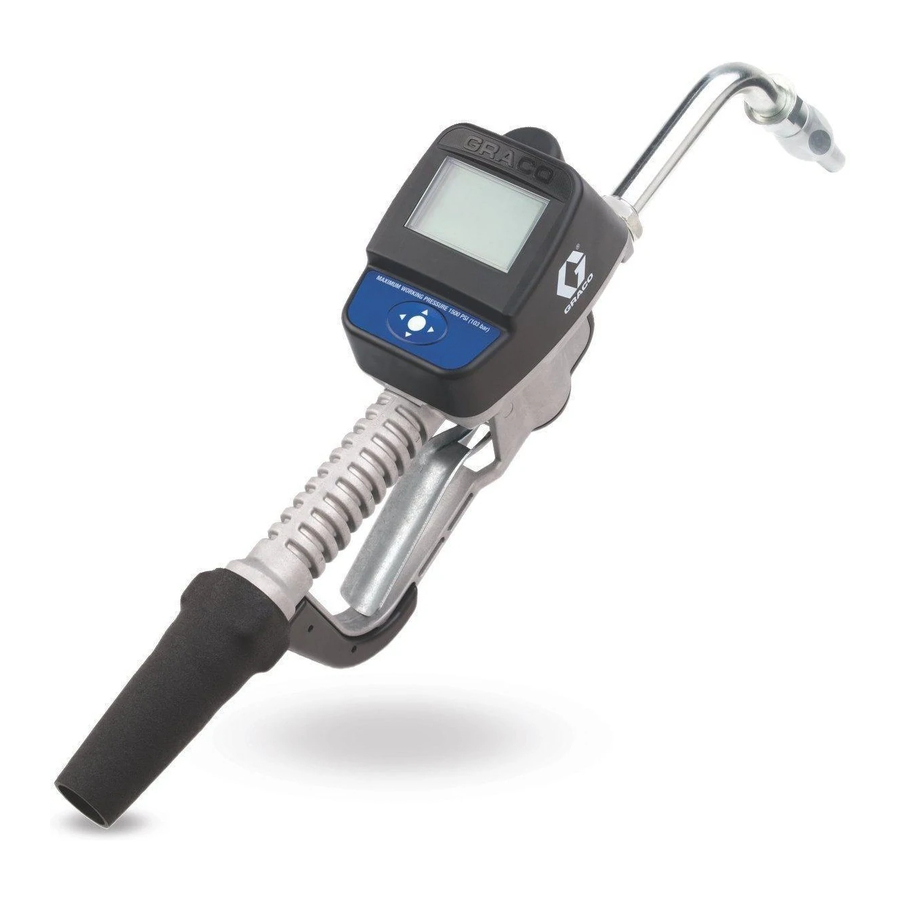
INSTRUCTIONS
SDM5 & SDM15 (Manual);
SDP5 & SDP15 (Preset)
Meters
For metered dispense of oils and 50:50 antifreeze/water mix fluids. For professional use
only.
Not for use in explosive atmospheres.
Maximum Working Pressure: 1500 psi (10 MPa, 103 bar)
Maximum Working Pressure (50:50 antifreeze/water mix): 900 psi (6.2 MPa, 62 bar)
Maximum Flow Rate:14 gpm (53 lpm)
List of Models page 2
Important Safety Instructions
Read all warnings and instructions in this
manual. Save these instructions.
NOTICE
This dispense valve is designed to dispense
petroleum-based lubricants and antifreeze only.
Do not dispense windshield washer solvent with
this dispense valve.
Preset Meter shown
ti11821
US Patent No: D594,490S
India Patent No: 219652
Korea Patent No: 30-555779
Taiwan Patent No: D130836
312865H
ENG
Advertisement
Table of Contents

Related Manuals for Graco 255348


Summary of Contents for Graco 255348
- Page 1 INSTRUCTIONS SDM5 & SDM15 (Manual); SDP5 & SDP15 (Preset) 312865H Meters For metered dispense of oils and 50:50 antifreeze/water mix fluids. For professional use only. Not for use in explosive atmospheres. Maximum Working Pressure: 1500 psi (10 MPa, 103 bar) Maximum Working Pressure (50:50 antifreeze/water mix): 900 psi (6.2 MPa, 62 bar) Maximum Flow Rate:14 gpm (53 lpm) List of Models page 2...
- Page 2 Models Models SDM5 Manual Dispense Electronic Meters Model Number Swivel Extension Description Nozzle Fluid Type 255348 1/2” npt(f) Flexible Extension Automatic, non-drip, quick close 255349 1/2” npt(f) Gear Lube Extension None-drip, quick close Gear Lube 255350 1/2” npt(f) Rigid Extension...
- Page 3 Models SDP15 Preset Dispense Electronic Meters Model Number Swivel Extension Description Nozzle Fluid Type 255353 3/4” npt(f) Rigid Extension Automatic, non-drip, quick close 255354 3/4” npt(f) Flexible Extension Automatic, non-drip, quick close 256838 1/2” npt(f) Rigid Extension Automatic, non-drip, quick close 256839 1/2”...
- Page 4 Warnings Warnings The following warnings are for the setup, use, grounding, maintenance, and repair of this equipment. The exclama- tion point symbol alerts you to a general warning and the hazard symbol refers to procedure-specific risk. Refer back to these warnings. Additional, product-specific warnings may be found throughout the body of this manual where applicable.
- Page 5 Warnings WARNING FIRE AND EXPLOSION HAZARD When flammable fluids are present in the work area, such as gasoline and windshield wiper fluid, be aware that flammable fumes can ignite or explode. To help prevent fire and explosion: • Use equipment only in well ventilated area. •...
- Page 6 The typical installation shown in F . 1 is only a guide. It Mounting Bracket Kit 249440 is available for resting the is not a complete system design. Contact your Graco dispense valve on a console. distributor for assistance in designing a system to suit your needs.
- Page 7 Installation Pressure Relief Procedure Air compressor: Follow manufacturer’s recommendations. Fluid supply container: Follow local code. To maintain grounding continuity when flushing or This equipment will stay pressurized until the pressure relieving pressure: hold a metal part of the dispense has been manually relieved. To reduce the risk of valve firmly to the side of a grounded metal pail, then serious injury from pressurized fluid, accidental spray trigger the valve.
- Page 8 Installation 3. Slowly open the main fluid valve. Installing Tube Extension (F . 5) a. Place the hose end (with no dispense valve connected) into a container for waste oil. b. Secure the hose in the container so it will not come out during flushing.
- Page 9 Installation Installing Nozzle (F . 6) ti10615A a. Thread new nozzle (33) onto extension (20). b. With an open-end adjustable wrench on flats of nozzle bushing, tighten firmly. • Only tighten nozzle with wrench on flats of the nozzle bushing. •...
- Page 10 Meter Overview Meter Overview Navigation and Modes Meter Display Adjusting Screen Contrast using ARROWS On the Setup Home Screen (page 11), use the LEFT and RIGHT ARROWS to adjust the screen contrast. • Darken the Screen: Press the RIGHT ARROW multiple times.
- Page 11 Setup Mode Screens Setup Mode Screens If you are in Operation Mode you must be on the Home Screen shown in F . 10, to access the Setup Mode Screens. (A complete description of the Home Screen is provided on page 18). To display the Home Screen: 1.
- Page 12 Main Screen of the list. the Setup screens. 2. Press center, ENTER button to confirm selection. Selected screen displays. 1. Software Version Number: Reference number. You may be asked to provide this number when contacting Graco for technical support. 312865H...
- Page 13 Setup Mode Screens Units/Limit Screen (F . 13) For All Meters Sets the units of measurement to pints, quarts, liters, or gallons. Manual Meters Preset Meters UNITS = QTS UNITS = QTS MANUAL LIMIT = 5.0 ti12191a . 13 Units/Limit Screen Features (F .
- Page 14 Setup Mode Screens Calibrate Screen (F . 14) For All Meters All meters include D - M D. Wrench Icon: Returns user to Main Screen. Recalibrates the meter for different fluids. J. Calibration Factor: Displays amount operator Table 1. Calibration Factors dispensed during meter calibration.
- Page 15 Setup Mode Screens Recalibrating the Meter (F . 14) 3. Dispense exactly 1 quart (or 1 liter) of fluid into a calibrated 1 quart (or 1 liter) container. The meter is shipped from the factory with the default calibration factor for 10W30 motor oil - at 70°F (21°C). The Calibration Factor will appear on the screen in This calibration factor is sufficiently accurate for most the Calibration Factor field (J).
- Page 16 Setup Mode Screens Preset Screen (F . 15) For Preset Meters Only To set Preset amounts (F . 15): Sets the default preset amounts. Typically, you would 1. Use the LEFT or RIGHT ARROWS to select one of enter amounts you most frequently dispense. the three amount fields (Q).
- Page 17 Setup Mode Screens Banner Screen (F . 16) Language Screen (F . 17) For All Meters For All Meters Creates the information banner displayed across top of Sets language preference for text displayed on meter. the Home, Manual and Preset Screens. Choices include English and Spanish.
- Page 18 Dispensing Fluid and Operation Mode Screens Dispensing Fluid and Operation Mode Screens FIRE HAZARD: Conductive metal surfaces on the meter must not make contact with any positively charged metal surface, including (but not limited to), the starter solenoid terminal, alternator terminal or battery terminal.
- Page 19 Dispensing Fluid and Operation Mode Screens Manual Dispense To dispense in Manual Mode: . 19) If display was asleep, press any button to wake it up. All Meters Preset shown MOBIL1 5W-20 MOBIL1 5W-20 10.56 MANUAL PRESET TOTALS ti12178a ti12180a .
- Page 20 Dispensing Fluid and Operation Mode Screens Preset Dispense (F . 22) L. Preset Quantities: Use the UP or DOWN ARROW to select field L on the task bar. Use the UP or DOWN ARROWS to scroll Preset Meters Only through the 3 available Preset Quantities (L). Each time you press the UP or DOWN ARROWS, one of the 3 preset amounts dis- MOBIL1 5W-20...
- Page 21 Dispensing Fluid and Operation Mode Screens To modify the amount selected: a. Use the UP or DOWN ARROW to scroll up or down to increase or decrease the amount shown in field L. Each time you press the UP or DOWN ARROW the amount will increase or decrease in increments of 0.1 units.
- Page 22 Dispensing Fluid and Operation Mode Screens To dispense in Preset Mode: 3. Squeeze trigger to begin dispensing fluid. The trig- ger may be locked during the dispense. If the display was asleep, press any button to wake up Fluid flows. The amount displayed counts up from the display.
- Page 23 Dispensing Fluid and Operation Mode Screens Totals Screen (F . 26) To display Totals Screen: All Meters If the display was asleep, press any button to wake up the display. MOBIL1 5W-20 3485 14953 MANUAL PRESET TOTALS ti12190a ti12243a . 26 .
-
Page 24: Troubleshooting
Calibrate the meter for the fluid that is accurate. fluid that is being dispensed. being dispensed. See Calibrate Screen, page 14. Meter leaks from cover/control. Poor seal at metering cover chamber. Contact your Graco distributor for repair or replacement. 312865H... - Page 25 Troubleshooting Problem Cause Solution Preset Models only - Trigger does not Excessive dirt buildup is causing trip Clean trip rod or replace (page 28). reset sufficiently to dispense fluid. rod to stick. Order Kit 255889. Meter leaks from twist lock nozzle. Twist lock nozzle has a damaged Replace nozzle.
-
Page 26: Error Codes
Check for low battery symbol and have shut off. replace batteries if indicated, page 27. For further assistance, contact Err 4 your Graco distributor. Flow has occurred in lockout condi- Navigate to Home screen. Then tion. re-enter Dispense Screen. In Manual Mode only. -
Page 27: Replacing The Battery
Service Service See Parts List, page 41, for reference numbers included in the following Service instructions. Replacing the Battery • Only use the size and type of batteries specified in this manual. Batteries required to meet life expectancy: • Energizer E91 •... - Page 28 Service Trip Rod Repair 4. With your finger, carefully lift up clip (D) to discon- nect battery lead (B) from battery module. (SDP5 & SDP15 Meters Only) Disassembly 1. Relieve Pressure, page 7. 2. Use a Torx (T20) wrench to remove 4 corner screws (A) located on the bottom of the meter (F .
- Page 29 Service 6. Remove two screws (D) holding reed switch board 8. Remove guard (9) by inserting your thumb or finger to the cover plate (F . 34). Keep these screws for behind the cover and pry it loose. Then slide guard reassembly.
- Page 30 Service 10. Place meter in a vise as shown in F . 38. Use new 13. Remove trip rod assembly from meter housing. trip rod from your kit (2) or a non-metal rod or dowel to push trip rod through meter housing (F .
- Page 31 Service Reassembly 5. Install trigger assembly (8) (F . 44). Push pin (19) through holes in trigger and trip rod assembly. Use all the new parts provided in the kit. Do not reuse the old parts. 1. Insert balls (3) in trip rod (2) (F .
- Page 32 Service 8. Reinstall reed switch board in meter housing. Use 2 screws (D) to secure reed switch PCB to cover NOTICE plate. Tighten screws until they bottom out. Do not use a screw driver or any other tool to lift up clip (D) when reconnecting battery lead (B).
- Page 33 Service 12. Replace 4 screws (A). Torque each to 24-35 inch pounds. ti11936a . 50 13. Install guard (9). ti12009a . 51 312865H...
- Page 34 STEM, valve 117436 SCREW, thd forming 120853 PIN, dowel 247344 SWIVEL, straight, 1/2-14 NPT, ▲ Replacement Danger and Warning labels, tags and includes 31a (used with 255348, cards are available at no cost. 255349, 255350, 255802, 255803, 255804, 256836, 256837) 312865H...
- Page 35 SDM5 & SDM15 Manual Meters Parts Torque to 25-35 IN. LBS Torque to 20-30 FT. LBS 17 / 47 ti11916b 312865H...
- Page 36 SDP5 & SDP 15 Preset Meters Parts SDP5 & SDP 15 Preset Meters Parts Part Description Part Description STEM, valve 115477 SCREW, mach, torx pan hd 120853 PIN, dowel 255889 KIt, repair, trip rod, includes 3a-3c 247344 SWIVEL, straight, 1/2-14 NPT, and instruction manual 312944 includes 31a (used with 255200, BALL,5 MM, carbide...
- Page 37 SDP5 & SDP 15 Preset Meters Parts Torque to 25-35 IN. LBS Torque to 20-30 FT. LBS 17 / 47 ti10617a 312865H...
- Page 38 Nozzle (33) and Extension (20) Kits Nozzle (33) and Extension (20) Kits Part No. Description Fluid Type Automatic, non-drip quick close nozzle with 255852* rigid extension. ti11827 ti11826 Automatic, non-drip quick close nozzle with 255853* ti11827 flexible extension ti11825 Non-drip, quick close nozzle with rigid 255854 Gear Lube ti11830...
- Page 39 Nozzle (33) and Extension (20) Kits Part No. Description Fluid Type Non-drip, quick close, high-flow nozzle with Oil and 255857 rigid extension Anti-freeze ti11829 ti11826 Non-drip, quick close, high flow nozzle with Oil and 255858 flexible extension Anti-freeze ti11829 ti11825 312865H...
- Page 40 Nozzle (33) and Extension (20) Kits Nozzle (33) Kits 255459* Automatic, non-drip, quick-close nozzle • BODY, nozzle • O-RING, packing • SPRING, compression • O-RING, packing • STEM, nozzle, valve • SEAT, valve 255460* Automatic, non-drip, quick-close nozzle Anti-freeze • BODY, nozzle •...
-
Page 41: Technical Data
Technical Data Technical Data Flow range* 0.26 to 14 gpm (1 to 53 lpm) Maximum Working Pressure 1500 psi (10 MPa, 103.4 bar) Maximum Working Pressure (50:50 antifreeze/water mix) 900 psi (6.2 MPa, 62 bar) Units of Measure pints, quarts, gallons, liters (factory set to quarts) Weight 5 pounds (2.26 kg) Dimensions (without extension) - Page 42 Graco warrants all equipment referenced in this document which is manufactured by Graco and bearing its name to be free from defects in material and workmanship on the date of sale to the original purchaser for use. Graco will, for a period of five (5) years from the date of sale, repair or replace any non-electronic part of the equipment determined by Graco to be defective.