Table of Contents
Advertisement
Quick Links
Instructions
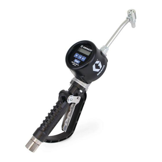
PM8 and PM20
Meters
For dispensing of petroleum based oils and anti-freeze. For professional use only.
Not approved for use in explosive atmospheres or hazardous (classified) locations.
1500 psi (10.3 MPa, 103 bar) Maximum Working
Pressure
200 psi (1.4 MPa, 14 bar) Maximum Working Pressure -
Anti-freeze models
Preset dispensing and measurement in gallons, quarts,
pints and liters. The meter is factory set to quarts.
Important Safety Instructions
Read all warnings and instructions in this
manual before using the equipment.
Save these instructions.
3A8307D
EN
Advertisement
Table of Contents

Related Manuals for Graco PM8


Summary of Contents for Graco PM8
- Page 1 Instructions PM8 and PM20 Meters 3A8307D For dispensing of petroleum based oils and anti-freeze. For professional use only. Not approved for use in explosive atmospheres or hazardous (classified) locations. 1500 psi (10.3 MPa, 103 bar) Maximum Working Pressure 200 psi (1.4 MPa, 14 bar) Maximum Working Pressure -...
-
Page 2: Models
Models Part No. Model Inlet Thread Fluid Extension Maximum Working Pressure 25U085 1/2 in. Anti-freeze Rigid 200 psi (1.4 MPa, 14.0 bar) 25U086 1/2 in. Anti-freeze Flex 200 psi (1.4 MPa, 14.0 bar) 25U087 1/2 in. BSPP Anti-freeze Rigid 200 psi (1.4 MPa, 14.0 bar) 25U088 1/2 in. -
Page 3: Table Of Contents
California Proposition 65 ....25 Graco Standard Warranty ....26... -
Page 4: Warnings
Warnings Warnings The following warnings are for the setup, use, grounding, maintenance, and repair of this equipment. The exclamation point symbol alerts you to a general warning and the hazard symbols refer to procedure-specific risks. When these symbols appear in the body of this manual or on warning labels, refer back to these Warnings. Product-specific hazard symbols and warnings not covered in this section may appear throughout the body of this manual where applicable. - Page 5 Warnings WARNING EQUIPMENT MISUSE HAZARD Misuse can cause death or serious injury. • Do not operate the unit when fatigued or under the influence of drugs or alcohol. • Do not exceed the maximum working pressure or temperature rating of the lowest rated system component.
-
Page 6: Typical Installation
Typical Installation Typical Installation KEY: PM8 or PM20 Metered Dispense Valve Fluid Shutoff Valve - Hose Reel Hose Hose Reel Fluid Inlet Hose Hose Reel Thermal Relief Kit (required). Part No. 237904. (Install downstream from pump.) NOTICE Flush lines before installing equipment in the system to remove contamination that can cause equipment damage or malfunction. -
Page 7: Installation
2. Trigger the dispense valve into a waste container to relieve pressure. PM8 and PM20 meters: use thread sealant when 3. Open any bleed-type master air valves and fluid connecting the meter to the hose. Do not use PTFE drain valves in the system. -
Page 8: Pre-Installation Procedure
Installation Pre-Installation Procedure Installing a Meter The reference letters used in the instructions on this page refer to Typical Installation, F . 1, page 6. To install a new meter in an existing installation, begin the instructions with Step 1 and Step 2. 1. -
Page 9: Operation
Preset amount may be configured. The display Holding the trigger in the open position overrides the value is 1.0. preset functionality of the PM8/PM20 meter. For additional operation directions, refer to the Preset Value Configuration Operation Flowchart, page 12, and the instructions on page 13. -
Page 10: Additional Dispense Limit (Addl)
Operation Additional Dispense Limit (AddL) To restore the factory default calibration factor, press the 0.1 button and the 10 button simultaneously, then release. AddL displays on the meter to identify the following value as the Additional Dispense Limit. The limit indicates how much additional fluid may be dispensed Verify Accuracy after reaching the Preset Value for a top-off application. -
Page 11: Dispense Instructions
Operation Dispense Instructions To reduce the risk of serious bodily injury, including fluid injection, never exceed the maximum working pressure of the valve you are using or the lowest rated component in your system. NOTICE The preset mechanism of the valve releases the trig- ger latch and allows the trigger to return to the closed position. -
Page 12: Operation Flowchart
Operation Operation Flowchart 3A8307D... - Page 13 Operation 1. Open the dispense nozzle and point it into the fill 8. To stop dispensing before the Preset amount is port or a container. reached, release the trigger latch by pulling the trigger toward the valve body, and releasing the 2.
-
Page 14: Battery Installation
Operation Battery Installation 5. Dispose of the batteries according to local regulations for battery disposal. 6. Insert new batteries as shown on the battery holder (negative and positive positions). Press down firmly. NOTE: The reference numbers in the following 7. Reinstall the battery pack. instructions refer to and F . - Page 15 Operation 12. Reinstall the impact guard (37). 3A8307D...
-
Page 16: Recycling And Disposal
Recycling and Disposal Recycling and Disposal End of Product Life At the end of the product’s useful life, dismantle and recycle it in a responsible manner. • Perform the Pressure Relief Procedure. • Drain and dispose of fluids according to applicable regulations. -
Page 17: Troubleshooting
Display does not activate or is show- Electronic control is malfunctioning Replace electronic control. Order ing unintelligible characters PM8/20 Electronics Kit. Kit includes electronic control, seal and mounting screws. Two or more batteries are installed Check the polarity of all four (4) bat- with incorrect polarity. -
Page 18: Alarms
Contact Graco Customer Service if recalibration is unsuccessful. bAtt Low Battery Alarm The battery voltage is too low to Replace batteries. -
Page 19: Notes
Notes: Notes: 3A8307D... -
Page 20: Parts
Parts Parts 16 13 28 27 32 31 Torque screws to 15 - 25 in-lb/1.7 - 2.8 N•m) Apply thin film of lubricant Install 35 without grease or oil. Use soapy water to lubricate. Torque to 60 - 72 in-lb/6.8 - 8.1 N•m) Torque to 15- 20 ft-lb/20.0 - 27.0 N•m) 3A8307D... - Page 21 28 ★✠ 15U700 PLUNGER, trigger lift Ref. Part Description Qty. 29 ★✠ 15U701 SPRINGS, secondary 1 ✜ BEZEL, PM8, PM20 30 ★✠ 15U704 SEAT, valve 1‡ BEZEL, PM8, AF 31 ★✠ SPRING, main valve 2 ✜ †✖‡ GASKET,PM8,BEZEL 32 ★...
- Page 22 Parts PM8/PM20 Pressure Drop 10 Weight Oil at 70°F (21°C) 3A8307D...
-
Page 23: Dimensional Drawing
103.5 mm 7.2 in. 183 mm PM8, flex 30.7 in. 780.0 mm 4.1 in. 103.5 mm 7.2 in. 183 mm PM8, gear lube 22.6 in. 575.0 mm 4.1 in. 103.5 mm 7.2 in. 183 mm PM20, rigid 21.4 in. 544.0 mm 4.1 in. -
Page 24: Technical Specifications
0.25 gpm 0.95 lpm Maximum static operating pressure PM8 Anti-freeze models 200 psi 1.38 MPa, 13.8 bar PM8/PM20 Oil and PM8 Gear Lube models 1500 psi 10 MPa, 102 bar Maximum Dynamic Operating Pressure* PM8 Anti-freeze Models 200 psi 1.38 MPa, 13.8 bar... -
Page 25: California Proposition 65
California Proposition 65 California Proposition 65 CALIFORNIA RESIDENTS WARNING: Cancer and reproductive harm – www.P65warnings.ca.gov. 3A8307D... -
Page 26: Graco Standard Warranty
With the exception of any special, extended, or limited warranty published by Graco, Graco will, for a period of twelve months from the date of sale, repair or replace any part of the equipment determined by Graco to be defective.