Table of Contents
Advertisement
Quick Links
Instructions
PSM
1K Precision Metering System
For accurate metering and dispensing of single-component materials. For professional
use only.
Not approved for use in explosive atmospheres or hazardous (classified) locations.
100 psi (0.7 MPa, 7 bar) Maximum Air Inlet Pressure.
See page 3 for model information, including maximum fluid working pressure and approvals.
Important Safety Instructions
Read all warnings and instructions in
this manual before using the equipment.
Save these instructions.
PSM Machine,
25 cc, Supply
Pump Feed, IQ
Dispense Valve
Direct Show
PSM Machine,
50 cc, Supply
Pump Feed, IQ
Dispense Valve
Direct Show
3A7273B
EN
PSM Machine,
100 cc, Supply
Pump Feed, IQ
Dispense Valve
Direct Show
PSM Control Box
Advertisement
Table of Contents

Related Manuals for Graco PSM


Summary of Contents for Graco PSM
- Page 1 Save these instructions. PSM Machine, 25 cc, Supply PSM Machine, Pump Feed, IQ 100 cc, Supply Dispense Valve Pump Feed, IQ Direct Show Dispense Valve Direct Show PSM Machine, 50 cc, Supply PSM Control Box Pump Feed, IQ Dispense Valve Direct Show...
-
Page 2: Table Of Contents
Schematics ....... 56 PSM Control Box ......9 I/O signals . -
Page 3: Models
✓ ✓ SST: Stainless steel material CER: Ceramic material Any PSM system can be converted from direct connection mode to remote connection mode by using remote kits. See Remote Kits in your PSM Repair-Parts Manual and order remote kits. See Related Manuals, page 2. -
Page 4: Warnings
Warnings Warnings The following warnings are for the setup, use, grounding, maintenance, and repair of this equipment. The exclamation point symbol alerts you to a general warning and the hazard symbols refer to procedure-specific risks. When these symbols appear in the body of this manual or on warning labels, refer back to these Warnings. Product-specific hazard symbols and warnings not covered in this section may appear throughout the body of this manual where applicable. - Page 5 Warnings WARNING FIRE AND EXPLOSION HAZARD Flammable fumes, such as solvent and paint fumes, in work area can ignite or explode. Paint or solvent flowing through the equipment can cause static sparking. To help prevent fire and explosion: • Use equipment only in well-ventilated area. •...
-
Page 6: Changing Materials
Warnings Changing Materials NOTICE Changing the material types used in your equipment requires special attention to avoid equipment damage and downtime. • When changing materials, flush the equipment multiple times to ensure it is thoroughly clean. • Always clean the fluid inlet strainers after flushing. •... -
Page 7: Typical Installation
Junction Box Communication Cable Bleed-type Master Air Valve I/O Communication Cable Supply Pump System Required, but not supplied PSM Control Box Customer Robot PSM Machine Customer Robot Control Box Air Line of Supply Pump Material Supply Line Air Line of PSM 3A7273B... -
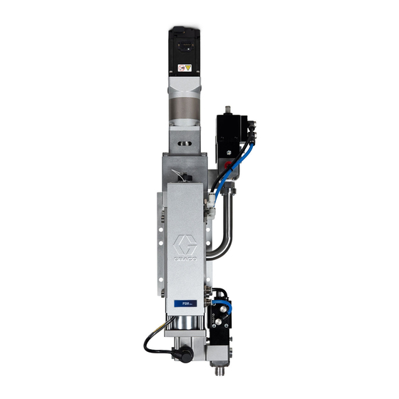
Page 8: Component Identification
Component Identification Component Identification PSM Machine, Supply Pump Feed 25 cc 100 cc 50 cc . 2: PSM Machine, Supply Pump Feed Key: AA Junction Box Assembly AB Dispense Valve AC Installation Plate AD Reload Valve AE Drive Assembly AF Base Unit AG Piston observation hole The sketch takes 25 cc as an example. -
Page 9: Psm Control Box
Component Identification PSM Control Box Left View Bottom View Front View . 3: PSM Control Box Key: BA Human Machine Interface (HMI) Display BB Control Power On/Off Buttons BC Emergency Stop Switch BD Main Power Switch BE Connection Plate 3A7273B... -
Page 10: General Information
There should not be any loose or damaged parts in the container. 3. Compare the packing slip against all the items in the box. Report any shortage or other inspection problems immediately. 4. Remove the PSM system components from the container. 3A7273B... -
Page 11: Locate And Install
(81 mm) 2.756 in. (70 mm) 5.512 in. (140 mm) . 4: Mounting Hole Dimensions for Installing the PSM Machine - 25cc 2 x Ø0.315 in. (8.0 mm) Through 4 x Ø0.335 in. (8.5 mm) Through 3.583 in. 3.583 in. - Page 12 2 x Ø0.315 in. (8.0 mm) Through 4 x Ø0.335 in. (8.5 mm) Through 3.583 in. 3.583 in. (91 mm) (91 mm) 2.756 in. (70 mm) 4.921 in. (125 mm) . 6: Mounting Hole Dimensions for Installing the PSM Machine - 100cc 3A7273B...
-
Page 13: Grounding
Improper grounding can cause electric shock. Grounding provides an escape wire for the electric current. PSM Machine (H, page 7): grounded through the PSM Installation Plate (AC, page 8). Use the supplied ground wire and clamp to ground the metal PSM Installation Plate (AC, page 8) or Customer Robot (G, page 7) to a true earth ground. -
Page 14: System Connections
General Information System Connections 1. Connect the PSM System Air Line (M, page 7) to the air inlet of Junction Box Assembly (AA, page 8). The maximum air pressure is 100 psi (0.7 MPa, 7 bar). The air flow is over 1 CFM. -
Page 15: Hmi Display Operation And Identification
HMI Display Operation and Identification HMI Display Operation and Identification Screen Navigation Diagrams NOTE: The interaction among screens can be achieved by selecting the icons on the screen. The following diagrams take icons as example. Automatic Screen 4 - Maintenance record (see page 24) Automatic Screen 5 - Job history (see page 24) - Page 16 HMI Display Operation and Identification Continued Pressure monitoring Automatic Screen 1 - Main (see page 20) (see page 19) See next page Enter 1492 in Advanced Screen System Main Screen ‘Password’ (see page 36) (see page 25) and select ‘Advanced’. Manual Screen 1 (see page 26) Manual Screen 2...
- Page 17 HMI Display Operation and Identification Continued NOTE: Click the button in any screen that has the button can display the System Main Screen, which is not showed in the following diagrams. System Main Screen (see page 25) Setup Screen 1 - Reload Setup Screen 7 - Pre-charge Setup Screen 8 - Depressurize (see page 27)
- Page 18 HMI Display Operation and Identification Continued Advanced Setup Screen - 1 (see page 34) Setup Screen 8 - Depressurize Advanced Setup Screen - 2 Setup Screen 1 - Reload (see page 33) (see page 35) (see page 27) Advanced Setup Screen - 3 (see page 35) 3A7273B...
-
Page 19: Automatic Screen 1 - Main
HMI Display Operation and Identification Automatic Screen 1 - Main Information bar • To illustrate the current status of equipment, such as Auto-Standby or Auto-Shot dispense. • To show error information when an alarm is active. Status bar • Job style: To show the current style number which defined on Setup Screen 5 - Style, see page 30. - Page 20 HMI Display Operation and Identification Pressure monitoring On Pressure Monitoring Screen, select to display Automatic Screen 1 - Main. Progress bar and dispense volume The current pressure is shown in psi. The operator can change the unit of pressure. See Pressure unit, page 34.
-
Page 21: Automatic Screen 2 - Main
Servo ready: Motor can be used or is working without problem. • Servo alarm: Something is wrong with the motor. Operator should push the reset button or send a remote reset signal. If reset does not work, the PSM control box needs to be restarted. 3A7273B... - Page 22 HMI Display Operation and Identification Control mode • Bead mode with preset value Automatic mode includes three control modes: shot mode, bead mode and sequence mode. • Shot mode: Per the style selected, the system will dispense at the preset volume and flow rate. For In Bead mode with preset value, the selected style the preset style, see Setup Screen 2 - Shot, number and target flow rate will be shown.
-
Page 23: Automatic Screen 3 - Main
In purge: The system is purging some material based on the preset flow rate and volume. • Error code: For error code information, see Appendix A - PSM Error Codes, page 52. The input signals display shows the current signal status from customer inputs. •... -
Page 24: Automatic Screen 4 - Maintenance Record
HMI Display Operation and Identification Automatic Screen 4 - Automatic Screen 5 - Job Maintenance record history . 12 Automatic Screen 4 - Maintenance record . 13 Automatic Screen 5 - Job history On the Automatic Screen 4 - Maintenance record, On the Automatic Screen 4 - Maintenance record, select the button to display the Automatic Screen... -
Page 25: Automatic Screen 6 - Error History
HMI Display Operation and Identification Automatic Screen 6 - Error System Main Screen history . 15 System Main Screen . 14 Automatic Screen 6 - Error history On the Automatic Screen 1 - Main, press button to On the Automatic Screen 6 - Error history, select the display the System Main Screen. -
Page 26: Manual Screen 1
HMI Display Operation and Identification Manual Screen 1 Other information For other information, please see Automatic Screen 2 - Main on page 21. . 16 Manual Screen 1 On the Manual Screen 1, Press ‘F1’ or select the button to display the System Main Screen. This button can only be selected when the system is in standby or alarm mode. -
Page 27: Manual Screen 2
The Manual Screen 2 is to check the signal exchange. display the System Main Screen. Select the For error code information, see Appendix A - PSM button to return to the previous screen. Select the Error Codes, page 52. - Page 28 HMI Display Operation and Identification Maximum reload time Reload request position Set reload time limit. If the reload process exceeds the • When the material in the supply pump system is time limit, the system will send out an alarm as a reload less than the percentage set here, the system will time out.
- Page 29 HMI Display Operation and Identification Setup Screen 2 - Shot Setup Screen 3 - Bead . 19 Shot Setup Screen . 20 Bead Setup Screen (Preset value) On the Shot Setup Screen, select the button to display the System Main Screen. Select the button to return to the previous screen.
- Page 30 HMI Display Operation and Identification Setup Screen 4 - Sequence Setup Screen 5 - Style . 22 Sequence Setup Screen . 23 Style Setup Screen On the Sequence Setup Screen, select the button On the Style Setup Screen, select the button to to display the System Main Screen.
- Page 31 Setup Screen 6 - Purge Purge alarm time Set the purge request time. When the equipment doesn’t dispense, the PSM control box will start the countdown for the time chosen by the operator. When . 24 Purge Setup Screen time is up, the system will send out the purge alarm signal and show ‘purge request’...
- Page 32 HMI Display Operation and Identification Setup Screen 7 - Pre-charge Maximum pre-charge time limit The operator may set the time in seconds the system may spend pre-charging. If pre-charging exceeds the set time, the system will activate the alarm to alert the operator the limit has been reached.
- Page 33 NOTE: Set different depressurization targets according to different materials. For detailed information, please contact your Graco distributor. • Max depressurization time: The operator may set a maximum time in seconds for the system to perform depressurization.
- Page 34 HMI Display Operation and Identification Advanced Setup Screen Password If this function is selected, a 4-digit number should be Advanced Setup Screen - 1 set. After the 4-digit number is set, the operator must be prompted to input the password before navigating to any of the setup screens.
- Page 35 • If ‘Display’ is selected, working mode will include If this function is enabled, the PSM system will run in Shot, Bead and Sequence mode. The operator will sequence mode. In this mode, the operator can edit the...
-
Page 36: Advanced Screen
HMI Display Operation and Identification Advanced Screen Press the button to enable or disable this function. The green color of the button indicates pressure check after homing is enabled. If this function is selected, the system pressure will be checked when the piston is at the home position. Pressure sensor offset . - Page 37 HMI Display Operation and Identification Piston move down Jog control pistons and push block move toward the outlet port. Push block Move down Piston Move up . 31 Piston move up or down Dispense valve Selecting this button enables testing of the Dispense Valve (AB) by controlling the opening or closing of the valve.
-
Page 38: Operation
NOTE: Air entering the machine should be filtered. 2. Locate the Power Switch (BD, page 9) at the left of the PSM Control Box (F, page 7) and turn the power on. 3. Press the Control Power on button (BB, page 9). -
Page 39: Prime The System
Machine (H, page 7) is free of air. set the lower pressure to 20 psi (0.14 MPa, 1.4 bar). 3. Go to the Advanced Screen of the PSM control box (F, page 7). Select ‘Piston move down’, the piston moves down until the sensor sends out the stop signal, then set the move speed to 0.2 cc/s. -
Page 40: Weight Check
Chose proper sealing medium according to different types of materials. 3. Dispense into a waste container to prime the PSM machine. 4. Place the cup under Dispense Valve (AB, page 8) and cycle the machine one time. -
Page 41: Pressure Relief Procedure
(required in the system). 2. Place a waste container below the Dispense Valve (AB, page 8). 3. Go to System main screen of the PSM control box (F, page 7), then select ‘Pressure relief’. The system will identify whether the Reload Valve (AD, page 8) is closed. -
Page 42: Flush The Equipment
Operation Flush the Equipment To avoid fire and explosion, always ground equipment and waste container. To avoid static sparking and injury from splashing, always flush at the lowest possible pressure. • Flush out old fluid with compatible solvent before introducing a new fluid. •... -
Page 43: Maintenance
Check the power and air pressure for the system. ✓ Clean and replace the static mixer. ✓ Inject grease to the lubricated kits of the PSM Machine (H, page 7). ✓ Clean and inject grease to the Inlet Valve (AE, page 8) and the Dispense Valve (AB, page 8). -
Page 44: Recycling And Disposal
Recycling and Disposal Recycling and Disposal End of Product Life At the end of the product’s useful life, dismantle and recycle it in a responsible manner. • Perform the Pressure Relief Procedure, page 41. • Drain and dispose of fluids according to applicable regulations. -
Page 45: Troubleshooting
Cartridge or pail empty Exchange cartridge or pail Supply pump clogged Clean supply pump Air in PSM machine Purge and prime the system Significant material leaking Pump shaft and/or shaft seal worn Remove pump shaft assembly and reinstall from pump seal... - Page 46 Troubleshooting Problem Cause Solution Leakage from needle Air in Dispense valve (AB, page 8) Slow speed purging 1. Verify Dispense Valve’s (AB, page 8) Dispense Valve (AB, page 8) not inlet air pressure. closed 2. Clean blockage between needle and seat.
- Page 47 Solution 1. Verify signal was correctly sent and System does not dispense or Signal error between platform and received. dispenses in the incorrect PSM control box 2. Verify signal cable is correctly amount/mode connected. Wrong “Dispense mode” Choose correct mode Wrong “Dispense type”...
-
Page 48: Dimensions
Dimensions Dimensions PSM Machine, Supply Pump Feed, 25 cc 6.14 in. (156 mm) 5.57 in. (141.50 mm) 23.22 in. (589.85 mm) . 36: PSM Machine Dimensions, 25 cc 3A7273B... -
Page 49: Psm Machine, Supply Pump Feed, 50 Cc
Dimensions PSM Machine, Supply Pump Feed, 50 cc 6.38 in. (162 mm) 6.04 in. (153.50 mm) 25.47 in. (646.85 mm) . 37: PSM Machine Dimensions, 50 cc 3A7273B... -
Page 50: Psm Machine, Supply Pump Feed, 100 Cc
Dimensions PSM Machine, Supply Pump Feed, 100 cc 6.38 in. (162 mm) 6.04 in. (153.50 mm) 29.01 in. (736.85 mm) . 38: PSM Machine Dimensions, 100 cc 3A7273B... -
Page 51: Psm Control Box
Dimensions PSM Control Box 16.93 in. (430.00 mm) 23.62 in. (600.00 mm) 9.92 in. (252.00 mm) . 39: Control Box Dimensions 3A7273B... -
Page 52: Appendix A - Psm Error Codes
Appendix A - PSM Error Codes Appendix A - PSM Error Codes Error Error Error Name Description Cause Solution code Type ---- No error ---- ---- ---- Error E-stop System emergency System Emergency Stop Switch Make sure the system is in safety... - Page 53 Appendix A - PSM Error Codes Error Error Error Name Description Cause Solution code Type Error Part B supplier Insufficient material Insufficient material in the supply Replace supply feeding tank is in low level for the supply system system Error of material lower level sensor Check position of the sensor or...
- Page 54 Appendix A - PSM Error Codes Error Error Error Name Description Cause Solution code Type Error De-pressurize Depressurize fails When depressurizing, material Execute system failed level in metering cylinder is too de-pressurization, or depressurize high by dispensing Reload Valve (AD) leaks...
- Page 55 Appendix A - PSM Error Codes Error Error Error Name Description Cause Solution code Type Deviation Illegal The current dispense The current dispense program check dispense program command program order is order is invalid and not able to be invalid and not able...
-
Page 56: Schematics
Schematics chematics 3A7273B... - Page 57 Schematics 3A7273B...
-
Page 58: I/O Signals
Schematics I/O signals Terminal Wire Label Signal Name Comments Number 1243 CUST_IN ESTOP + Dry contact, passive signal, normally closed 1244 CUST_IN SETOP - 1611 CUST_IN RELOAD To work with CUST_ IN COMMON, dry contact, normally open. 1613 CUST_IN JOB START 1621 CUST_IN DISPENSE When connected to CUST_ IN COMMON, signal is... - Page 59 Schematics Terminal Wire Label Signal Name Comments Number 1612 CUST_OUT STANDBY To work with CUST_ OUT COMMON, dry contact, normally open. 1614 CUST_OUT READY 1622 CUST_OUT INJOB When the signal output is ON, the signal line is 1624 CUST_OUT IN DISPENSE connected to the CUST_ IN COMMON;...
-
Page 60: Timing Chart
Schematics Timing Chart Always precharge and reload after each job None precharge and reload after each job 3A7273B... - Page 61 Schematics Distributed IO or gateway precharge and reload after each job Always precharge and reload after each job with flow rate command 3A7273B...
- Page 62 Schematics None precharge and reload after each job with flow rate command Distributed IO or gateway precharge and reload after each job with flow rate command 3A7273B...
- Page 63 Schematics Purge with reloading after purge Purge with depressurization after purge 3A7273B...
-
Page 64: Technical Specifications
25 cc: 24 lb 25 cc: 11 kg PSM Machine 50 cc: 28 lb 50 cc: 13 kg 100 cc: 35 lb 100 cc: 16 kg PSM Control Box 71 lb 32 kg Operating Temperature IQ Dispense Valve 158°F 70°C Notes All trademarks or registered trademarks are the property of their respective owners. -
Page 65: California Proposition 65
California Proposition 65 California Proposition 65 CALIFORNIA RESIDENTS WARNING: Cancer and reproductive harm – www.P65warnings.ca.gov. 3A7273B... -
Page 66: Graco Standard Warranty
With the exception of any special, extended, or limited warranty published by Graco, Graco will, for a period of twelve months from the date of sale, repair or replace any part of the equipment determined by Graco to be defective.