Table of Contents
Advertisement
Quick Links
Instructions - Parts
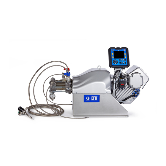
EFR
Electric Fixed-Ratio Proportioner
For use with two-component sealant and adhesive materials. For professional use only.
Not approved for use in explosive atmospheres or hazardous locations.
2000 psi (13.8 MPa, 138 bar) Maximum Fluid Inlet Pressure
3500 psi (24.1 MPa, 241 bar) Maximum Fluid Outlet Pressure
See page 3 for model information.
Important Safety Instructions
Read all warnings and instructions in this
manual and in related manuals before
using the equipment. Save these instruc-
tions.
3A6165J
EN
Advertisement
Table of Contents

Related Manuals for Graco EFR


Summary of Contents for Graco EFR
- Page 1 Instructions - Parts 3A6165J Electric Fixed-Ratio Proportioner For use with two-component sealant and adhesive materials. For professional use only. Not approved for use in explosive atmospheres or hazardous locations. 2000 psi (13.8 MPa, 138 bar) Maximum Fluid Inlet Pressure 3500 psi (24.1 MPa, 241 bar) Maximum Fluid Outlet Pressure See page 3 for model information.
-
Page 2: Table Of Contents
Operation ....... . 19 Graco Information ......70 Startup . -
Page 3: Models
High-Wear High-Wear An EFR may be configured without pumps by designating “X” for both pump selections. Inlet/Outlet Fitting selec- tion is required to specify the fittings shipped with the system. Pumps can be purchased and assembled sepa- rately before placing the system into service. See the Z-Series Chemical Pumps Instructions-Parts manual. -
Page 4: Warnings
Warnings Warnings The following warnings are for the setup, use, grounding, maintenance, and repair of this equipment. The exclama- tion point symbol alerts you to a general warning and the hazard symbols refer to procedure-specific risks. When these symbols appear in the body of this manual or on warning labels, refer back to these Warnings. Product-specific hazard symbols and warnings not covered in this section may appear throughout the body of this manual where applicable. - Page 5 Warnings WARNING SKIN INJECTION HAZARD High-pressure fluid from dispensing device, hose leaks, or ruptured components will pierce skin. This may look like just a cut, but it is a serious injury that can result in amputation. Get immediate surgical treatment. •...
- Page 6 Warnings WARNING MOVING PARTS HAZARD Moving parts can pinch, cut or amputate fingers and other body parts. • Keep clear of moving parts. • Do not operate equipment with protective guards or covers removed. • Equipment can start without warning. Before checking, moving, or servicing equipment, follow the Pressure Relief Procedure and disconnect all power sources.
-
Page 7: Keep Components A (Red) And B (Blue) Separate
Warnings Keep Components A (Red) and A (Red) and B (Blue) B (Blue) Separate Components NOTE: Material suppliers can vary in how they refer to plural component materials. For all machines: Cross-contamination can result in cured material in fluid lines which could cause serious injury or damage •... -
Page 8: Component Identification
B-Side Outlet Drain/Relief Valve* Pump Yoke Shroud Required components supplied with the system. Electric Driver EFR systems configured without pumps are provided Incoming Power Connection with drain/relief valves, which must be installed after Pump Inlets the pumps are assembled, but before placing the Pump Outlets system into service. -
Page 9: Typical Installation
Typical Installation Power Cord with User Supplied Dedicated Inlet Regulators Circuit Protection Dispense Valve* EFR Proportioner A Supply System* B Supply System* . 2: Typical Installation Required accessories not supplied with the proportioner. Optional accessories not supplied with the proportioner. -
Page 10: Advanced Display Module (Adm)
Component Identification Advanced Display Module (ADM) User Interface TI12362a1 . 3: ADM Component Identification - Front Buttons Callout Button Function Callout Button Function Soft Defined by application using ADM. System Enables/disables system. When Keys enable/ system is disabled, temperature disable control and dispense operation are Cancel Cancel a selection or number entry... - Page 11 Component Identification ti12363a1 . 4: ADM Component Identification - Rear Key: ADM Module Status LEDs (AN) Conditions AJ Flat Panel Mount AK Model Number AL USB Module Interface Module Status LED AM CAN Cable Connections Signal Description AN Module Status LEDs AP Accessory Cable Connections Green on System is powered up.
-
Page 12: Installation
Grounding provides an escape wire for the electric current. . 5: Power Cord EFR: grounded through the power cord (customer sup- 2. Remove the four screws to separate the junction plied). box cover (BA) and disconnect switch (C) from the junction box (BB) on the electrical driver. - Page 13 Installation NOTE: Inside the junction box, power wires are 4. Attach the ground wire to the ground terminal inside pre-installed to terminals 2T1 and 4T2 on the disconnect the junction box as shown in F . 8. block. Refer to F .
-
Page 14: Install Vented Oil Cap Before Using Equipment
Installation Install Vented Oil Cap Before Using Equipment The driver gear-box is shipped from the factory pre-filled with oil. The temporary unvented cap (PX) prevents oil leaks during shipment. This temporary cap must be replaced with the vented oil cap (PY), supplied with the equipment, before use. -
Page 15: Setup
After placing the EFR in the desired area of operation: 4. Connect the supply systems. a. Install feed pumps for component A (Red) and NOTE: Make sure the EFR is placed on a level surface. See Dimensions on page 66 for space requirements. B (Blue) supply drums. See F . -
Page 16: Flushing
Setup Flushing 5. Attach the fluid outlet hoses to the pump outlets (K). Adapter fittings may be required, see Outlet Fit- tings on page 42. To avoid fire and explosion, always ground equipment and waste container. To avoid static sparking and injury from splashing, always flush at the lowest pos- sible pressure. -
Page 17: Driver And Yoke Position
Setup Driver and Yoke Position The driver and yoke position must be set for the volume 4. Verify the correct pumps are mounted for your mix mix ratio of the system. ratio by volume. Divide the displacement of the B-side pump by the displacement of the A-side pump (B/A) to NOTE: The mix ratio is only determined by the size of the calculate the volume ratio. - Page 18 Setup Change Driver and Yoke Position 5. Loosen the three nuts (D2) below the driver tie rods. There are specific driver positions for each mix ratio set- piston ting. To adjust the position of the electric driver: 1. Turn the power disconnect switch (C) to the OFF position.
-
Page 19: Operation
NOTE: The EFR is tested with oil at the factory. Flush eyes. To prevent cross-contamination of the equip- out the oil with a compatible solvent before dispensing. -
Page 20: Shutdown
5. Perform the Pressure Relief Procedure on page 1. Press the enable/disable key on the ADM disable the EFR, and verify it is inactive. 2. Relieve pressure and shut off the supply systems. See your appropriate supply system manual. -
Page 21: Adjust Material Inlet Pressure
3-4 provide material to the pump inlet. times. Use only enough feed pressure to adequately feed the EFR pumps. The minimum feed pressure is 70 1. Verify that the material supply pump does not pro- psi (0.48 MPa, 4.83 bar). -
Page 22: Maintenance
If oil is low, valve manual open fill cap (FB) and add Graco Part No. 16W645 ISO 220 silicone-free synthetic EP gear oil. See F . 11. Clean dispense valve check... -
Page 23: Change The Oil
Once the pump is parked, the pump ft-lb (25-30 N•m). will stop moving. 4. Open the fill cap (FB) and add Graco Part 16W645 2. Turn the power disconnect switch (C) to the OFF ISO 220 silicone-free synthetic EP gear oil. Check position. -
Page 24: Adm - Battery Replacement And Screen Cleaning
Maintenance ADM - Battery Replacement and 6. Turn the power disconnect switch (C) to the ON position. Screen Cleaning 7. Navigate to Maintenance Screen 1 on the ADM (see page 55). Press to enter Calibration mode. Battery Replacement 8. Press the icon to begin calibration. -
Page 25: Troubleshooting
3. Turn the power disconnect switch OFF. Try the recommended solutions in the order given for NOTE: For Online help, visit http://help.graco.com for each problem, to avoid unnecessary repairs. Also, causes and solutions to each error code. determine that all circuit breakers, switches, and con- trols are properly set and wiring is correct before assum- ing there is a problem. - Page 26 Troubleshooting Problem Cause Solution Material imbalance Inadequate flow from pump; Increase fluid supply to proportion- ing pump: • Use minimum 3/4 in. (19 mm) ID supply hose, as short as practi- Clean inlet strainer screen Worn pump inlet valve ball/seat or gasket Erratic pump movement Pump cavitation...
-
Page 27: Efr Error Codes
Troubleshooting EFR Error Codes Error Code Code Description Cause Solution A4NX High current motor Inlet pressure too high, causing Reduce inlet supply pressure. retract stroke to require too much torque Pump sizes too large for motor to Reduce combined pump size. - Page 28 Troubleshooting Error Code Code Description Cause Solution CACV Comm. Error Voltex No 24 VDC power supply to ADM Reconnect or replace CAN cable Dynamic Mix Valve connecting FCM and ADM. If CAN Module connection good, check 24V power supply wiring inside the controller enclosure.
- Page 29 Troubleshooting Error Code Code Description Cause Solution F4NX Setting Exceeds Pump cannot cycle fast enough to Reduce flow rate Max Output achieve the desired flow rate Increase pump sizes L1TA Red Tank Sensor Bad level sensor(s) Replace level sensor(s) Failure L2TA Red Low Material Tank low on material...
- Page 30 Troubleshooting Error Code Code Description Cause Solution L6TB Blue Auto Refill No material is actually being fed Make sure the feed pumps are Timeout operating properly Loose level sensor connection Check for loose or disconnected wires or plugs Bad level sensor Replace level sensor MAA0 Pump A Cycles...
- Page 31 Troubleshooting Error Code Code Description Cause Solution P2DA Low Pressure Pressure A is below user-defined Check feed system for low or empty Deviation Outlet A dispense pressure limit material. Increase dispense rate. Check pressure settings on setup screen. P2DB Low Pressure Pressure B is below user-defined Check feed system for low or empty Deviation Outlet B...
- Page 32 Troubleshooting Error Code Code Description Cause Solution P3DA High Pressure Pressure A exceeds user-defined Inspect for hardened material or Outlet A limit obstructions to flow. Attempt to purge material at a reduced flow rate. Reduce operating pressure by reducing flow rate and/or restriction in the hose and valve.
- Page 33 Troubleshooting Error Code Code Description Cause Solution P3FB High Pressure Inlet Supply pressure is too high Reduce inlet supply pressure. Inlet pressure should not exceed 67% of outlet pressure. Outlet operating pressure is too low Increase outlet operating pressure. Outlet pressure should be at least 1.5x inlet pressure.
- Page 34 Troubleshooting Error Code Code Description Cause Solution P4FB High Pressure Pressure B exceeds user-defined Check settings on feed system, Alarm Inlet B dispense pressure limit. decrease pressure if necessary. Check pressure settings on setup screen. P6DA Pressure Sensor Loose or bad sensor connection to Check to make sure that the Error Outlet A Motor Control Module...
- Page 35 Troubleshooting Error Code Code Description Cause Solution P7DB Pressure Imbalance Dispense line is clogged First try purging fresh material High B through the system. Then relieve pressure and check for cured material or obstructions in the dispense valve. Orifice restrictions sized incorrectly Adjust orifice restrictions to balance pressure of A and B materials Out of material...
-
Page 36: Parts
Parts Parts EFR Common System Parts 3A6165J... -
Page 37: Fluid Section
Parts Fluid Section A Side Pump B Side Pump 3A6165J... -
Page 38: Driver And Yoke Assembly
Parts Driver and Yoke Assembly Apply blue thread-locker. Torque to 0.8-1.13 N •m (7-10 in-lbs). Torque to 20-27 N •m (15-20 ft-lbs). Torque to 23-32 N •m (17-23 ft-lbs). Torque to 67-81 N •m (50-60 ft-lbs). Torque adapters to 122-135 N •m (90-100 ft-lbs). - Page 39 SCREW, flange head 110† 191872 191929 FITTING, adapter 16V153 WASHER, retaining 113† 295847 121116 FITTING, elbow, 3/4 npt 26B019 KIT, adm, efr 114† 801787 113833 FITTING, tee 124* CABLE, can 115† 100615 516308 BUSHING 125** 26B020 BRACKET, adm (includes 128, 116†...
-
Page 40: Electrical Assembly
Parts Electrical Assembly 240V 480 V 240V 480 V Systems Systems Systems Systems Ref. Description Part Qty. Part Qty. Ref. Description Part Qty. Part Qty. 1 --- 1 25E103 229† PLUG, headless 3/4 102726 COVER, pump, lower 25E103 4 114182 221†... - Page 41 233 † LABEL, safety, danger --- - 126891 234† NUT, strain relief, 1” - --- 240*† HARNESS, transformer, efr Not shown † Included in Transformer Kit 26A703 Replacement safety labels, tags, and cards are avail- able at no cost. 3A6165J...
-
Page 42: Accessories
Accessories Accessories Outlet Fittings Part Description NOTE: See the MD2 Valve Instructions-Parts manual for more information on mixers and accessories. 158683 90°, 1/2-NPT (m) x 1/2-NPT (f), Steel 100206 1/2-NPT (m) x 1/4-NPT (f), Steel Applicator 123094 90°, 1/2-NPT (m) x JIC-08 (m), Steel 127324 1/4-NPT (m) x JIC-04 (m), Steel Part Description... - Page 43 Accessories Communications Gateway Module (CGM) The EFR Communication Gateway Module allows the user to control an EFR through an external control device such as a PLC. See EFR Communication Gate- way Module manual for more information. Part Description 25B127 DeviceNet CGM Kit...
-
Page 44: Advanced Display Module (Adm) Operation
Advanced Display Module (ADM) Operation Advanced Display Module (ADM) Operation When main power is turned on by turning the power dis- connect switch (C) to the ON position, the splash screen will be displayed until communication and initialization is complete. To begin using the ADM, the machine must be on and enabled. -
Page 45: Adm Screen Overview
ADM Screen Overview ADM Screen Overview Home Screen System Active Sequence Error and Events State Selected Display Status of Valve To select a sequence, use the navigation keys to high- light the active sequence bar. Then press the Enter but- to open a drop down menu where the desired sequence can be selected. - Page 46 ADM Screen Overview Along the right side of the home screen, there are icons De-Pressurize: When pressed, the de-pressurize icon that will allow the user to prime, park, de-pressurize, and purge the unit. will open the dispense valve, which will relieve pressure in the pump lines.
-
Page 47: Voltex Dynamic Mix Valve Run Screen
Tank Stand Status Information NOTE: This screen will only be displayed if the Voltex Dynamic Mix Valve is connected to the EFR Network. NOTE: The tank stand status information and icons will only be shown when the tank stand is connected to the 1. -
Page 48: Index Menu
NOTE: If the flow rate is set to zero, the EFR will wait for the specified amount of time before performing the next shot size. - Page 49 Until the trigger signal is received, the EFR will wait before playing the shot size shown beside the selected check box. Once the external trigger is received, the EFR will proceed through the sequence.
- Page 50 ADM Screen Overview Sequence Definition Screen 2 Setup Screen 1 This screen allows the user to copy, delete, and name This screen allows the user to change the dispense selected sequences. Use the arrow keys to select a mode, rate units, pressure units, pressure imbalance sequence from the list.
- Page 51 Alarm: If the pressure goes below the minimum or Alarm: This is the amount of time the EFR will wait after above the maximum, the current dispense will stop and the idle period has been reached. This allows time for further dispensing will not be allowed until the alarm is the robot to move into the purge location.
- Page 52 Motor Ramp Up Time: This changes the amount of time in milliseconds the motor takes to get to the RPM set- point. EFR Dispense Wait: This will cause the EFR to wait until the Voltex Dynamic Mix Valve motor is up to speed before dispensing.
- Page 53 ADM Screen Overview Setup Screen 5 • The low level sensor will generate a low level devia- tion. This screen allows the user to specify the operating • When the high level sensor does not see material, parameters for off-board, integrated tanks and indicate automatic refill will begin and continue until either which positions have level sensors installed.
- Page 54 ADM Screen Overview Advanced Screen 1 Advanced Screen 2 This screen allows the user to change the language, This screen allows the user to view and upgrade soft- date, and time shown on the ADM. The user can also set up a password and change the screen saver here. ware installed on the system.
- Page 55 A red arrow pointing up signifies a top changeover, and number is entered in that field, and the corresponding a red arrow pointing down signifies a bottom change- pump or valve cycles exceeds that value, the EFR will over. generate and log an advisory informing the user of the condition.
- Page 56 PLC. Integration inputs must be There are 20 pages, each holding 10 events. The 200 enabled by checking the box for the EFR to use the sig- most recent events are shown. nal. If the check box is not checked, the EFR will ignore the signal.
- Page 57 ADM Screen Overview Integration Screens 2 and 3 USB Plug-In Screen This screen will appear when a CGM is connected. This screen will appear when a USB device is plugged into the ADM. This screen displays the setup screen for a connected CGM.
-
Page 58: Software Update
See the following Icon table. Icon Description Update successful. 4. Insert and press EFR software upgrade token (TK, Update unsuccessful. part no. 17Y711) firmly into slot. NOTE: There is no preferred orientation of token. Update complete, no changes necessary. -
Page 59: I/O Integration
Digital Input: System Enable: When this digital input pin is ON, the EFR system • 5-24V is ON will be active, and when this digital input pin is OFF, the EFR system • 0V is OFF will be inactive. Analog Flow Rate: This Analog Flow Rate is only used when a sequence is in operator mode. -
Page 60: I/O Integration Cable Colors
Connector 4 I/O Integration Cable Colors The following table shows the wire color codes for the M12, 8 pin bare leads 13.1 ft (4 m) pigtail cable (128441) supplied with the EFR for I/O integration from EFR connector 4. Color White... -
Page 61: I/O Integration Diagrams
Once the system ready pin is ON, in the diagrams shown below. the EFR is ready to receive commands from the PLC. NOTE: A 100ms delay is suggested between each I/O To put the system in the active state, press the signal. - Page 62 If a shot is in operator mode throughout a sequence, the EFR will only dispense that shot if the trigger pin is ON. Once the trigger pin is OFF, the EFR will continue to the next shot in the sequence.
- Page 63 I/O Integration Sending the sequence select bits is optional. If the sequence select bits are not sent, the EFR will use the current selected sequence. EFR Discrete Signal Stop Sequence Automation Inputs (EFR Outputs) System Ready Alarm Active Valve Signal...
-
Page 64: Remote Sequence Selection
If the I/O integration cable (128441) is also sequence. desired, connect the splitter (127948) to connector 4 of the EFR, then connect the integration cable (128441) and cable 17Z431 to the splitter. If the I/O integration ADM Connector #1 (AP) cable is not desired, connect cable 17Z431 to connector 4 of the EFR. -
Page 65: Wiring Diagrams
Wiring Diagrams Wiring Diagrams NOTE: See the APD20 Advanced Precision Driver Instructions manual for driver internal wiring. Power Wiring Customer Ground Customer Power In Customer Ground X1-X3 X6-X9 Customer H1-H3 Power In H6-H9 3A6165J... -
Page 66: Dimensions
Dimensions Dimensions A Machine Mounting Holes 21.5 in. (55 cm) For 3/8 in. (10mm) Mounting Fasteners B Machine Mounting Holes 21.1 in. (54 cm) C Total Machine Height 22 in. (56 cm) D Total Machine Length 50 in. (127cm) E Total Machine Width 22.5 in. -
Page 67: Technical Specifications
Technical Specifications Technical Specifications Metric Maximum fluid working pressure ‡ 3500 psi 24 MPa, 241 bar Maximum fluid temperature 120°F 50°C Fluid circulation ports 1/4 NPS(m) 200-240V, 1ph, 50/60 Hz Line voltage rating 400-480V, 1ph, 50/60 Hz Stainless steel, zinc-plated carbon steel, brass, tungsten Wetted parts carbide, chrome, fluoroelastomer, PTFE, ultra-high molec- ular weight polyethylene, silicon nitride... -
Page 68: California Proposition 65
Technical Specifications California Proposition 65 CALIFORNIA RESIDENTS WARNING: Cancer and reproductive harm – www.P65warnings.ca.gov. 3A6165J... - Page 69 Technical Specifications 3A6165J...
-
Page 70: Graco Standard Warranty
With the exception of any special, extended, or limited warranty published by Graco, Graco will, for a period of twelve months from the date of sale, repair or replace any part of the equipment determined by Graco to be defective.