Table of Contents
Advertisement
Quick Links
Instructions
®
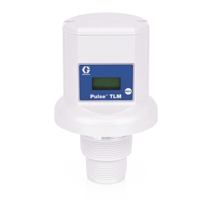
Pulse
Level Monitor)
Measures the distance between the device and the surface of the fluid beneath it to
determine the volume of fluid within a tank. Use with a Pulse operating system only.
Intended fluids: oil, waste oil, automatic transmission fluid (ATF), anti-freeze, windshield
washer solution, and waste water.
Not approved for use in European explosive atmosphere locations. For professional use
only.
Part No.: 25M449
Important Safety Instructions
Read all warnings and instructions in this manual.
Save these instructions.
•
Do not over tighten TLM into tank
bung! Over tightening can cause perma-
nent damage and result in inaccurate
readings.
•
Do not use thread sealant or adhesive!
Many of these products are chemically
incompatible with the ABS plastic. PTFE
tape is acceptable.
Contains Model XBee S2C Radio, IC: 1846A-XBS2C.
The TLM contains FCC ID MCQ-XBS2C. This device complies with Part 15 of the FCC Rules.
Operation is subject to the following two conditions:
•
This device may not cause harmful interference.
•
This device must accept any interference received, including interference that may cause
undesired operation.
TLM (Tank
NOTICE
3A5411J
EN
Advertisement
Table of Contents

Related Manuals for Graco Pulse TLM


Summary of Contents for Graco Pulse TLM
- Page 1 Instructions ® Pulse TLM (Tank 3A5411J Level Monitor) Measures the distance between the device and the surface of the fluid beneath it to determine the volume of fluid within a tank. Use with a Pulse operating system only. Intended fluids: oil, waste oil, automatic transmission fluid (ATF), anti-freeze, windshield washer solution, and waste water.
-
Page 2: Table Of Contents
Graco Extended Tank Level Monitor Warranty ......20 Graco Information ....... . . 20... -
Page 3: Warnings
Warnings Warnings The following warnings are for the setup, use, grounding, maintenance, and repair of this equipment. The exclamation point symbol alerts you to a general warning and the hazard symbols refer to procedure-specific risks. When these symbols appear in the body of this manual or on warning labels, refer back to these Warnings. - Page 4 Warnings WARNING EQUIPMENT MISUSE HAZARD Misuse can cause death or serious injury. • Do not operate the unit when fatigued or under the influence of drugs or alcohol. • Do not exceed the maximum working pressure or temperature rating of the low- est rated system component.
-
Page 5: Set Up
Set Up Set Up Register the TLM It is recommended that the TLM be registered prior to installation. Do not install or service this equipment The TLM operating parameters are unless you are trained and qualified. controlled by the Pulse software and set up by Installing and servicing this equipment the System Administrator. -
Page 6: Configure The Tlm
TLM Display TLM Display Configure the TLM Press the Display button (A) again to Registration configure the TLM with a new profile. Displays REGISTER. Successful registration The display reads CONFIG OK, as adds a second line: OK. Registration failure shown in F . -
Page 7: Installation
Installation Installation NOTICE NOTICE The TLM will not operate correctly if tilted Do not over tighten TLM into tank bung! more than 2° from the surface of the tank Over tightening can cause permanent liquid. damage and result in inaccurate readings. The TLM will not operate correctly if the Do not use thread sealant or adhesive! TLM is mounted less than 5 in. -
Page 8: Installation Examples
Installation Installation Examples Correct Incorrect Correct Incorrect Placement Placement Placement Placement Correct Incorrect Correct Incorrect Placement Placement Placement Placement 3A5411J... -
Page 9: Operation
Operation Operation View Data Take Measurement The TLM can be configured with the Pulse software to take a reading at predefined times. Press and release the display button (A). Data appears on the display (B) (F . 7); each screen lasting a few seconds before going on to the next. -
Page 10: Take Measurement - New Profile
Operation Take Measurement - New Refill the Tank Profile After a tank is refilled from an oil distributor or a waste oil tank is emptied by a waste oil service provider, press the display button (A) . 7) on the TLM to ensure that the TLM will maintain the most current tank volume status. -
Page 11: Troubleshooting
Monitor is not reporting Out of RF range. Add Graco Extender to Pulse System. Order Graco Part No. scheduled readings RF obstruction. 17F885 - US/Canada; 17F886 - EU; 17F887 - UK;... - Page 12 Monitor display is cracked. Replace TLM. Weak or no RF signal Changes/obstructions in RF Add Graco Extender to Pulse System. Order Graco Part No. pathway (i.e., vehicles, over- 17F885 - US/Canada; head doors, etc.) 17F886 - EU; 17F887 - UK;...
- Page 13 Troubleshooting Problem Cause Solution Monitor readings are inaccu- Tank geometry incorrectly See Tank Level Monitor Soft- rate. defined. ware Guide or PC Software Guide for details. Tank Level Monitor has not Manually push DISPLAY but- been updated with latest ton on TLM. adjustments made within The profile ID on the Pulse sys- tem.
-
Page 14: Service
Service Service NOTICE After the TLM has been installed, the only Do not attempt to separate the battery holder additional maintenance or service necessary from the TLM. The power and ground wires is changing the batteries. are secured to the bottom of the battery holder. - Page 15 Service . 12 Replace cover (3) and secure it with the two cover screws (11). Torque cover screws to 18 to 22 in.-lbs (2.03 to 2.48 N•m) to prevent water leakage into the TLM electronics. NOTE: If a torque wrench is not used, verify there are no gaps under the screw heads and no gaps under the cover flange.
-
Page 16: Parts
Parts Parts TLM Dimensions Ref Part No. Description HOUSING COVER SEAL, cover HOLDER, battery BATTERY, alkaline AA SCREW, mach, pnh, 131260 torx Kit 25P682 includes 3, 7 . 13 3A5411J... -
Page 17: Tank Specifications
Tank Specifications Tank Specifications Vertical Tank: Horizontal Cylindrical Tank: • Maximum Volume = 999,999 gal- • Maximum Volume = 999,999 gal- lons or liters. lons or liters. • Tank walls must be uniformly verti- • Tank end walls must be flat; they cal from empty level to full (F . -
Page 18: Obround Tank
Tank Specifications Obround Tank: • Maximum Volume = 999,999 gal- lons or liters. • Tank end walls must be flat; they cannot be any other shape includ- ing belled (F . 17). If applicable, use non-standard tank. max height 30 ft. (91.4 m) width 30 ft (9.14 m) length 30 ft... -
Page 19: Technical Specifications
Technical Specifications Technical Specifications Tank Level Monitor (TLM) Metric Compatible Fluids oil, waste oil, automatic transmission fluid (ATF), anti-freeze, windshield washer solution, and waste water Ultrasonic Tank Depth Measurement 5 in. to 30 ft. 12.7 cm to 9.14 m range Fluid Level Measurement Accuracy +/- 1.8 in. -
Page 20: Graco Extended Tank Level Monitor Warranty
With the exception of any special, extended, or limited warranty published by Graco, Graco will, for a period of twenty four months from the date of sale, repair or replace any part of the equipment determined by Graco to be defective.