Table of Contents
Advertisement
Quick Links
IMPORTANT NOTE:
REMEMBER ALWAYS TO CONNECT
FORWARD PAINTER LINE
TO MOTHER VESSEL,
BEFORE LAUNCHING THE BOAT.
WHEN YOU ORDER SPARE PARTS,
OR HAVE ANY QUESTIONS,
PLEASE CONTACT:
Supplier:
MARITIME PARTNER
Postboks 776, Sentrum
6001 AALESUND, NORWAY
Telefon: +47 70 11 65 65 Telefax: +47 70 11 65 55
E-mail: office@maritime-partner.com
www.maritime-partner.com
Advertisement
Chapters
Table of Contents

Related Manuals for Yanmar 4LHA-HTP


Summary of Contents for Yanmar 4LHA-HTP
- Page 1 IMPORTANT NOTE: REMEMBER ALWAYS TO CONNECT FORWARD PAINTER LINE TO MOTHER VESSEL, BEFORE LAUNCHING THE BOAT. WHEN YOU ORDER SPARE PARTS, OR HAVE ANY QUESTIONS, PLEASE CONTACT: Supplier: MARITIME PARTNER Postboks 776, Sentrum 6001 AALESUND, NORWAY Telefon: +47 70 11 65 65 Telefax: +47 70 11 65 55 E-mail: office@maritime-partner.com www.maritime-partner.com...
- Page 2 Content Section Description Doc.no. Rev. VOLUME 2 Operation / User Instructions, Continue: Engine - Yanmar 4LHA-STP Operation Manual Parts Catalog Service Manual maritime partner as...
- Page 3 OPERATION MANUAL YANMAR YANMAR DIESEL ENGINE 4 L H A - H T P / - H T Z P 4 L H A - D T P / - D T Z P 4 L H A - S T P / - S T Z P Be sure to read this manual for safe and proper operation.
-
Page 4: Proposition 65 Warning
Congratulations on your choice of YANMAR product from YANMAR DIESEL ENGINE CO., LTD. This manual describes operation, periodic inspection and maintenance servicing for the ENGINE manufactured by YANMAR DIESEL ENGINE CO., LTD. Please read this manual carefully before use, and operate... - Page 5 • C o n s t a n t efforts are made to improve the quality and performance of Yanmar products, s o s o m e details included in this Operation Manual may differ slightly from your engine.
-
Page 6: Table Of Contents
INTRODUCTION £ INDEX • • " 1. FOR SAFE OPERATION 1.1 Warning Symbols 1.2 Safety Precautions 1.3 Location of product safety Labels " " 2. EXPLANATION OF PRODUCT 9~22 Use, Driving System etc. • • 2.2 Engine Specificitions • * 1 0 - 1 2 2.3 Names of Parts •... - Page 7 5. M A I N T E N A N C E & INSPECTION 42-54 5.1 List of Periodic Inspections • 5.2 Periodic Inspection Items 44-54 5.2.1 Inspection after Initial 50 Hrs. Operation 5.2.2 Inspection Every 50Hours • 5.2.3 Inspection Every 250 Hrs. orl yr. 5.2.4 Inspection Every 500 Hrs.
-
Page 8: For Safe Operation
1. FOR SAFE OPERATION Following the precautions described in this manual will enable you to use this engine with comple satisfaction. Failure to observe any of the rules and precautions, however, may result in injury, bums, fires, and engine damage. Read this manual carefully and be sure you fully understand it before beginning operation. -
Page 9: Safety Precautions
1.2 Safety Precautions (Observe these instructions for your own safety.) Precautions for Operation Burns from Scalding 44. DANGER # Never remove the filler cap of the fresh water cooler while the engine is still hot. Steam and hot water will spurt out and seriously burn you. Wait until the water temperature has dropped, then wrap a cloth around the cap and loosen it slowly. -
Page 10: Safety Precautions
Alcohol A WARNING • Never operate the engine while you are under the influence of alcohol or when you are ill or feel unwell as this results in accidents. Safety Precautions for inspection Battery Fluid A DANGER • Battery fluid is diluted sulfuric acid. It can blind you if it gets in your eyes, or burn your skin. -
Page 11: Location Of Product Safety Labels
1,3 Location of product Safety Labels To insure safe operation, warning device labels Warning device labels, Parts numbers have been attached. Their location is shown in Part Code No. the diagram below and next page. Keep the labels < D 128296-07300 from becoming dirty or torn and replace them if 120324-07240... - Page 12 ® A g g WARNING CAUTION • E x p o s e d m o v i n g p a r t s . • C a n c a u s e injury. 128296-07360 • Hot surface •May cause burn 1 28296-07 300 - 8 -...
-
Page 13: Explanation Of Product
The installation, fitting and surveying of this engine all require specialized knowledge and engineering skills. Consult Yanmar's local subsidiary in your region or your distributor or dealer. n o - Never modify this product or release the limit devices (which limit engine speed, fuel injection quantity, etc.). - Page 14 • 4LHA-HTP/-HTZP 4LHA-HTZP 4LHA-HTP Engine model Vertical water cooled 4-cycle diesel engine Type No. of clinders 100X110 Bore X Stroke 3.455 Displacement 118 (160)/3300 Fuel stop power at cranksheift kw(hp)/rpm 91.2/(124)/3100 Cont. power at crankshaft. kw(hp)/rpm 3700 ± 25 High idling 750 ±...
- Page 15 • 4LHA-DTP/-DTZP 4LHA-DTP 4LHA-DTZP Engine model Vertical water cooled 4-cycle diesel engine Type No. of clinders 100X110 Bore X Stroke 3.455 Displacement Fuel stop power at crankshaft 147(200)73300 kw(hp)/rpm Cont. power at crankshaft. 116/(158)/3100 kw(hp)/rpm 3700 ± 25 High idling 750 ±...
- Page 16 • 4LHA-STP/-STZP 4LHA-STZP 4LHA-STP Engine model Vertical water cooled 4-cycle diesel engine Type No. of clinders 100X110 Bore X Stroke 3.455 Displacement Fuel stop power at crankshaft 177(240)73300 kw(hp)/rpm Cont. power at crankshaft. 140/(190)/3100 kw(hp)/rpm 3700 ± 25 High idling 750 ±...
-
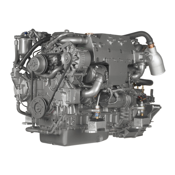
Page 17: Names Of Parts
2.3 Names of parts Fuel injection valve Inter Cooler Fuel oil filter Fuel injection pump Lube oil fiiter Alternator [Note] This illustration shows the 4LHA-HTP engine. - Page 18 Fuel injection valve Inter cooler Fuel oil filter Lube oil cooler Fuel injection pump Lube oil filter :er cooler Turbo charger Fresh wal Alternator Exhaust manifold cooler Cooling fresh water pump Starter moter Sea water pump [Note] This illustration shows the 4 L H A - D T P er' - 1 4 -...
- Page 19 Fuel injection valve Inter Cooler Fuel oil filter Stern driving devices B R A V O , M E R C R U I S E R Fuel injection pump Turbocharger Mixing elbow AHemator Exhaust tube [Note] This illustration shows the 4 L H A - H T Z P engine. - 1 5 -...
- Page 20 (for 4LHA-HTP/HTZP). For 4LHA-DTP/-DTZP/-STP/-STZP, dram the dust and water periodicaly removing the drain plug at the bottom of filter. Feeds fuel to the fuel injection pump builting-in the fuel injection pump (4LHA-HTP/- • F u e l feed pump F?4LHA-DTP/-DTZP/-STP/STZP, it is attached with the fuel injection pump.
- Page 21 The control equipment consists of the control panel and remote control handle, which are connected by the wires and cables to the control levers for remote control operation. 2.5.1 Control Panel (Optional) The control panel has the following gauges and alarm devices (optional accessories): •...
- Page 22 New C-type New D-type • Available switches (for alarm) and senders (for meter) 4LHA-HTP 4LHA-HTZP 4LHA-DTP 4LHA-DTZP 4LHA-STP 4LHA-STZP Battery not charge C.W.high temperature L.0 low pressure C.W. level Exhaust (C.S.Wflow) Boost Gear oil (Stern) Fuel filter Tachometer C.W. temperature LO.pressure...
- Page 23 (1) Gauges and Equipment Functions Gauges & Equipment OFF: The switch key can be inserted or removed. Starter switch Starter switch All power is turned off. Before starting Before starting L^dunng operation L^dunng operation ON: For engine operation. Gauges and alarm devices are turned on. GLOW °...
- Page 24 (2) Functions of Alarm Devices (Alarm Buzzer & Lamps) 1) The alarm buzzer sounds when any warning lamp (except the charge lamp) comes on. 2) Warning lamps come on when sensors (switchs) detect an abnormality during engine operation. The warning lamps in the display column of the control panel are off during normal o p e r a t ^ but come on as follows when an abnormality arises: Charge Lamp The lamp comes on when there is a charging failure.
- Page 25 Function of Alarm Devices After Starting Before starting START Key Operation — O N —ON Alarm Buzzer Alarm Lamps O f f Charge Lamp Cooling Water Temperature Engine Oil Pressure Fuel filter Gear Oil Boost 2.5.2 Remote Control Handle This engine is controlled by the remote control handle located in the cockpit. The speed control lever on the engine side and clutch lever on the marine drive are connected by remote control cable with the remote control handle in the cockpit.
- Page 26 • Starting and stopping MT-3 Put the handle in NEUTRAL. This puts the clutch in the disengage position (stop) and idles the engine at a low speed. • Forward Move the handle from NEUTRAL to A FWD (forward). This engages the clutch in X"'/ forward and simultaneously increases the engine speed.
- Page 27 3. BEFORE OPERATION 3.1.1 Fuel r-fNOTICE] Use of fuels not recommended In this Operation Manual may cause a decrease in engine performance and cause components to fail. (1) Selection of fuei Use the following diesel fuels for best engine performance: IS08217 DMA, BS2869 A l or A2 Fuels equivalent to Japanese Industrial Standard, JIS.
-
Page 28: Cooling Water
Quicksilver Power Trim and Steering Fluid Power trim oil or S A E 10W-30 or 10W-40 engine oil For further more instructions, refer to the maker's manual. Follow the maker's instructions for the marine gears. / HSW450A2 (HURTH)(4LHA-HTP/-DTP)x (HSW630A1 (HURTH)(4LHA-STP) 3.1.3 Cooling Water ^NOTICE] Be sure to add LLC to cooling fresh water. - Page 29 (1) Handling of Cooling Water 1) Choose LLC which will not have any adverse effects on the materials (cast iron, aluminum, copper, etc.) of the engine's fresh water cooling system. 2) Strictly use the proper mixing ratio of LLC to fresh water as instructed by the LLC maker. 3) Replace the cooling water periodically according to the maintenance schedule given in this operation manual.
-
Page 30: Filling The Fuel Tank
A DANGER Fires from Oil Ignition • Be sure to use the correct type of fuel when refueling. Mistakenly filling with gasoline or the like will result in ignition. • Be sure to stop the engine before refueling. If you spill fuel, wipe such spillage carefully. •... - Page 31 • 4LHA-HTP/-HTZP ©Open the cock on the fuel oil inlet pipe line. ©Loosen the air bleeding screw on the fuel filter Air bleeding screw by turning 2 - 3 times to the counter-clockwise using a screw driver. ©Feed the fuel with the priming pump.
-
Page 32: Supplying Marine Drive Oil
3.4 Supplying Marine Drive Oil ^ ^ ^ ^ ^ ^ • Marine gear (HSW450A2, HSW630A1) -[NOTICE] For the marine gear, follow the maker's Do not overfill. Overfilling will cause oil to be sprayed instructions. out during operation and effect the efficiency of the marine drive. - Page 33 ©Supply cooling water slowly to the fresh water tank so that no air bubbles will develop. Supply until the water overflows For 4LHA-HTP/-HTZP from the filler port. ©After supplying cooling water, fasten the filler cap firmly. If loose, trouble will occur due to water leakage.
- Page 34 ©Check the rubber hose connecting the subtank to with the fresh water tank. If the hose is not water-tight a lot of coolling water will be con- sumed. Rubber hose Fresh water tank a n * y — — f Full limit levels Low limit level-»...
-
Page 35: Supplying Engine Lube Oil
éfr theckiii«ii& c m u t o doom viife^ 1;^^ When lube oil, gear oil, and cooling water are put in for the first time, or after they have been replaced, their levels should be checked after a trial operation. Oil and water will be distributed to the various parts during the operation, lowering the levels of oil and water. -
Page 36: How To Operate
4. HOW TO OPERATE A W A R N I N G • Neveroperate the engine whiie you are under the influence of alcohol or when you are ill or feel unwell as this results in accidents. A W A R N I N G Exhaust Gas Poisoning •... - Page 37 If the cooling water runs out too often, or if the water level in the fresh water tank falls without any change in the subtank water level, there may be some leakage of water or air. In such cases, consult your Yanmar dealer or distributor without delay. (6) Checking the Remote Control Handle Be sure to check that the remote control handle lever moves smoothly before use.
-
Page 38: Daily Starting
4.2 Checking the Control Panel and Alarm Devices Be sure to check the alarm devices and other instruments on the panel before and after the engine. If the devices are not working properly, it is impossible to prevent any problems arising from insufficient oil and water in the engine. -
Page 39: Restarting After Starting Failure
4.3.3 Restarting After Starting Failure When attempting to restart the engine after starting failure, be sure that the engine is at a complete ^ stop before turning the starter switch key. If the engine is restarted while the engine still has not stopped, the pinion gear of the starter motor will be damaged. -
Page 40: Adjusting The Engine Speed
4.4 Adjusting the Engine Speed pfNOTICEJ Adjust the speed of the engine by moving the For a new engine be especially careful remote control handle slowly and smoothly. Move not to change speeds abruptly or attach the handle forward and adjust the speed between a heavy load for the first 50 hours of low speed and high speed. -
Page 41: Check During Operation
4.6 Check During Operation Always be on the look out for problems during engine operation. Pay particular attention to the following. (1) Is sufficient water being discharged from the seawater outlet pipe ? If the discharge is small, stop the engine immediately, identify the cause and repair. (2) Is the exhaust color normal ? The continuous black exhaust smoke shows engine overloading. -
Page 42: Stopping The Engine 3
4.7 Stopping the -[NOTICE] Stop the engine in accordance with the following procedures. Stopping the engine suddenly after ©Stop the boat. operating at high speed without cool- Put the remote control handle in NEUTRAL to ing it down will cause the engine tem- perature to rise quickly resulting in stop the boat. -
Page 43: Operation Procedure
4.8 Operation Procedure The following diagram shows the procedures for operation explained up to this point. Parts of the operation may differ depending on the marine drive and remote controi system being used. Accompanying operation manuals should be read carefully and understood. Incpecfcn Bvl'irt S l j r i i n i j l Starting Operation t t i t i m ;... - Page 44 ©After draining off the water, tighten the water drain cocks and reinstall the side cover on the seawater pump. Seawater Oil cooler Loosen bolts Seawater pump Inter cooler Fresh water cooler For 4LHA-HTP/-HTZP - 4 0 -...
- Page 45 Lube oil filter O Fresh water Fresh water cooler For 4LHA-HTP/-HTZP Fresh water cooler (3) Cleaning, Draining Fuel Oil, Greasing • Clean the outside of the engine wiping off any dust or oil. • To prevent condensation inside the fuel tank, either drain off the fuel or fill the tank.
-
Page 46: Maintenance & Inspection
5. MAINTENANCE & INSPECTION Conduct Periodic Inspection for Your Safety. The functions of engine components will degenerate and engine performance will fall according to the use of the engine. If periodic inspections are not performed, you may encounter unexpected troubles while cruising at sea, and consumption of fuel or lube oil may become excessive and exhaust gas and engine noise may increase. -
Page 47: List Of Periodic Inspections
5.1 List of Periodic Inspections 'Daily and periodic inspection are important to keep the engine in its best condition. The following is a summary of inspection and servicing items by inspection interval. Periodic inspection intervals vary depending on the uses, loads, fuels and lube oils used and handling conditions, and are hard to establish definitively. - Page 48 eriodic Inspection Item 5.2.1 Inspection After Initial SOHrs. Operation (1) Replacing the Engine Lube Oil and Lube Oil Filters (1st time) A C A U T I O N Precautions for Removing Hot Oi! to Prevent Burns If extracting oil from the engine while it is still hot, do not let the oil splash on you.
-
Page 49: Inspection Every 50 Hours
5.2.2 Inspection Every 50 Hours (1) Draining the Fuel Tank (local supply) ©Put a pan under the drain to catch the fuel. ©Loosen the drain cock at the bottom of the fuel tank, and drain off any water and dirt collected inside. - Page 50 Drain periodically to keep the filter from becoming clogged. When ther<| is a lot of drain collected in the oil/water separator at the bottom of the fuel filter, the fuei filte alarm lamp on the control panel (optional) will light up. (4LHA-HTP/-HTZP) 1)4LHA-HTP/-HTZP ©Close the fuel cock on the fuel pipe line.
- Page 51 The capacity of the specified alternator and battery is sufficient for regular operation, however, the capacity may be insufficient, if they are used for other purposes such as lights inside the boat, etc. Consult your Yanmar dealer or distributor. - 4 7 -...
- Page 52 5.2.3 Inspection Every 250 Hrs. or 1 yr. (1) Replacing the Fuel Filter 1) 4LHA-HTP/-HTZP ©Close the fuel cock of the fuel tank. ©Drain the fuel from the fuel drain cock at the bottom of fuel filter. See. 5.2.2(3) ©Remove the connectors of the wiring and remove the alarm switch using spanner.
- Page 53 (2) Replacing Engine Lube Oil and Lube Oil filter. (See 5.2.1(1)) ^3) Replacing Cooling Fresh Water Cooling performance drops when the cooling water is contaminated with rust and scale. Even if LLC is added, the cooiing water must be periodically replaced because the properties of the agent will degenerate.
- Page 54 (high idle) or low speed (idle) position. If either the high speed or the low speed side does not make contact with stopper, adjust as follows: (4LHA-HTP/-HTZP) ©Remove the threaded area and the con- necting pivot of the remote control cable •Setteng bolts from the governor lever.
- Page 55 Inspection and adjustment must be made to correct opening/closing timing lags of the intake/ exhaust valves which might arise due to initial parts wear. This inspection requires specialized knowledge and techniques. Consult your Yanmar dear or distributor. (8) Inspection and Adjustment of Fuel Injection Valve (1st Time) Inspection and adjustment are necessary to obtain optimal fuel injection to ensure the good engine performance.
-
Page 56: Inspection Every 1000 Hrs. Or 4 Yrs
5.2.5 Inspection Every 1000 Hrs. or 4 yrs. (1) Adjustment of Intake/Exhaust Valve clearance (2nd time & after) This maintenance requires specialized knowledge. Consult your Yanmar dealer or distributor. Adjustment is necessary to maintain the correct timing for the opening and closing of valves. -
Page 57: Inspection Every 2000 Hrs
1) Cracks and loss of impeller; flaws or excessive wear of impeller tips and side faces. If any, replace the damaged part (consult Yanmar dealer or distributor) (Note) The impeller must be replaced periodically (every 2000 hours). - Page 58 Adjustment necessary to maintain proper contact of valves and seats. This maintenance requires specialized knowledge. Consult your Yanmar dealer or distributor. (3) Inspection and Adjustment of Fuel Injection Timing Fuel injection timing must be adjusted to ensure optimal engine performance.
- Page 59 Drain excessive in the Drain the water in the 5.2.2(3) W/O separator of the Lamp goes on W/O separator (4LHA-HTP/-HTZP) fuel filter MNOTICE] ^Warning Devices Do not run the engine with alarm devices still unrepaired. are Faulty. Trouble will progress and a serious problems may result.
- Page 60 Reference Measure Probable Cause Trouble Replace V-belt; adjust 5.2.4(1) V-belt broken or loose OCharge lamp does tension not go out Check fluid level, Battery defective. during operation specific gravity; replace. 5.2.2(4) Alternator power Ask for repairs. generation failure •Starting Failures 3.2.2 Resupply fuel;...
- Page 61 •tk JUEL OVERFLOW FUEL HIGH PRESSURE PIPE MARKS OF NAME PIPING LUB. OIL FILTER FUEL OIL FILTER > FUEL INJECTION PUMP / (OIL PRESSURE SENDER)^ (UNION) SCREW JOINT FLANGE JOINT OIL PRESSURE SWITCH FUEL OIL INLET EYE JOINT OIL PRESSURE INSERTION JOINT DRILLHOLE COOLING FRESH...
- Page 62 FUEL OVERFLOW FUEL HIGH PRESSURE PIPE LUB. OIL FILTER MARKS OF FUEL OIL FILTER NAME PIPING (OIL PRESSURE SENDER)^ FUEL INJECTION PUMP, LUB. OIL COOLER > (UNION) FUEL OIL INLET SCREW JOINT OIL PRESSURE SWITCH FLANGE JOINT EYE JOINT INSERTION JOINT DRILLHOLE FUEL INJECTION NOZZLE COOLING FRESH...
- Page 63 MARKS OF FUEL INJECTION PUMP NAME PIPING FUEL OVERFLOW (OIL PRESSURE SENDER)iii (UNION) PRESSURE SWITCH SCREW JOINT • FLANGE JOINT EYE JOINT INSERTION JOINT FUEL OIL FILTER "0 DRILLHOLE COOLING FRESH WATER PIPING COOLING SEA OIL PUMP WATER PIPING LUB, OIL PIPING SAFETY VALVE FUEL, OIL PIPING FROM WATER HEATER"...
- Page 64 FL I EL INJECTION PUMP (OIL PRESSURE SENDER) % LUB. OIL FILTER MARKS OF > NAME PIPING FUEL OVERFLOW FUEL OIL INLET OIL PRESSURE SWITCH (UNION) LUB. OIL COOLER SCREW JOINT FLANGE JOINT EYE JOINT INSERTION JOINT FUEL OIL FILTER DRILLHOLE FUEL INJECTION NOZZLE COOLING FRESH...
- Page 65 Color coding "I I Procured by customer 1+2+3<2.5m->20mm Battery | 1+2+3< Sm-AOmm B Black (Cross sectional area) W White Yellow Blue G Green Orange Lg Light green Lb Light blue Br Brown Pink Gray Pu Purple E 1 E 3 I E 0 I Details of coupler A-A Note:...
- Page 66 "1 (4LHA-DTPADTZPASTP/-ST2P) ; Procured by customer 1+2+3<2.5m-20mm* Batlery ! l + 2 + 3 < 5m-40mni» (Cross sectional area) * Battery S w i t c h ^ ) l.*Growplug Relay Starter Relay Starter I'M- Eng. Oil Pressure CW.Temp switch Earth Bolt SwHch Alternator...
- Page 67 Detail» of 4 5 ^ "coupler-C *C.W. Temp. * Boost Sender *Eng.0il Pressure Sender Sender Color coding Charge Eng. OII P. Black Fuer (Ilter swicth (4LHA-HTP/-HTZP) C.W. Temp. While Exhaust Blue Gear Red/Black Blue/Black Boost Note: Yellow/ White C.W. Level * Oplonal.
-
Page 68: Warranty Service
If the problem has already been reviewed with the Service Manager, contact the owner of the dealership or the General Manager. • If your problem still has not been resolved to your satisfaction, contact your Yanmar local Subsidiary Company. - Page 69 YANMAR DIESEL ENGINE CO., LTD. YANMAR DIESEL AMERICA CORP. 951 CORPORATE GROVE DRIVE, BUFFALO GROVE, ILLINOIS 60089 U.S.A. TEL: 1-847-541-1900 FAX: 1-847-541-2161 User's record Date of purchase Place of purchase (Name of dealer) 49961-205430...
- Page 70 YANMAR PARTS CATALOG YANMAR ENGINE MODEL aLHA-STE(P) 4LHA-DTZEIP) aLHA-STZE(P) aLHA-HTE P aLHA-DTE P aLHA-HTZE P (Product by YMA) Published Sep.,2001 000Y00R4782...
- Page 71 Lubricationg system 6. The contents of this parts catalog are subject to change without prior notice. 7. Be sure to use only genuine Yanmar part for repairs. If other parts are used, the life of the engine may be shortened.
- Page 72 How to read this Parts Catalog. 1. Parts mentioned in this Parts Catalog may not necessarily be standard equipping parts. 2. Parts change may be made without prior notice. 3. Form of this Parts C a t a l o g . Y0OF2161 (1997.09.01) jSM-IH-PT D = 4JH-0TZA...
- Page 73 CONTENTS MODEL : 4LHA-ST/DT/HT/(Z)E(P) P / C No. : Y00R4782 PUBLISHED: 2 0 0 1 / 9 P/C NEWS No. G R O U P G R O U P N A M E N A M E Fig. No. Fig.
- Page 74 CONTENTS MODEL : 4LHA-ST/DT/HT/(Z)E(P) P / C No. : Y00R4782 PUBLISHED: 2 0 0 1 / 9 P/C NEWS No. G R O U P G R O U P N A M E N A M E Fig.No. Fig.No. FUEL INJECTION PUMP(4LHA-ST/DT(Z)E(P)) FUEL INJECTION PUMP(4LHA-HT(Z)E(P)) GOVERNOR...
- Page 75 Y00R4782 F i g . I CYLINDER BLOCK JifflUNo. i fi, jtffll/No. (1) ^ B 3 l * ^ a f * - r . l i n e d ) FLYWHEEL SIDE FUEL INJECTION P U M P...
- Page 76 Y00R4782 (2001.09.27) A= 4LHA-STE (P) D= 4LHA-DTZE (P) B= 4LHA-STZE (P) E= 4LHA-HTE (P) Fig. • CYLINDER BLOCK C= 4 L H A - D T E (P) F- 4LHA-HTZE (P) DESCRIPTION PARTS No. REF.No. C i D i E A ! B BLOCK ASSY, CYLINDER - 0 1 5 6 0...
-
Page 77: Cylinder Block
Y00R4782 */Vy97Qy<? Fig. I CYLINDER BLOCK 1 i n c . (1) ~ 3 1 FLYWHEEL SIDE 1(1)^^1-55 FUEL INJECTION P U M P... - Page 78 Y00R4782 (2001.09.27) A= 4 L H A - S T E (P) D= 4 L H A - D T Z E (P) B= 4LHA-STZE (P) E= 4 L H A - H T E (P) Fig. I CYLINDER BLOCK C= 4 L H A - D T E (P) F= 4 L H A - H T Z E (P) Q'ty DESCRIPTION...
- Page 79 Y00R4782 Fig.fc GEAR HOUSING REFER TO F i g . l REFER TO F i g . 2 8 . 2 9 EFER TO F i g. 5...
- Page 80 Y00R4782 (2001.09.27) A= 4 L H A - S T E ( P ) D = 4 L H A - D T Z E ( P ) B = 4 L H A - S T Z E ( P ) E= 4 L H A - H T E ( P ) F i g X Q E A R HOUSING C= 4 L H A - D T E ( P ) F= 4 L H A - H T Z E ( P ) Q'ty...
-
Page 81: Flywheel Housing
Y00R4782 FLYWHEEL HOUSING 4LHA-STZE (P) 4LHA-DTZE (P) 4LHA-HTZE (P) - 1 4... - Page 82 Y00R4782 (2001.09.27) A= 4 L H A - S T E ( P ) D = 4 L H A - D T Z E ( P ) B = 4 L H A - S T Z E ( P ) E= 4 L H A - H T E ( P ) Fig.U FLYWHEEL HOUSING C= 4 L H A - D T E ( P ) F= 4 L H A - H T Z E ( P ) DESCRIPTION...
-
Page 83: Mounting Foot(4Lha-St/Dt(Z)E(P))
Y00R4782 7 3 > T O ^ - h (4LHA-ST/DT (Z) E (P) ) Fig. MOUNTING FOOT (4LHA-ST/DT (Z) E (P)) R E F E R TO F i g . l (A/ / . / OPTIONAL ^ n ^ . OPTIONAL ^ n ^ . - Page 84 Y00R4782 (2001.09.27) A = 4 L H A - S T E ( P ) D = 4 L H A - D T Z E ( P ) B = 4 L H A - S T Z E ( P ) E= 4 L H A - H T E ( P ) Fig.H MOUNTING F00T(4LHA-ST/DT(Z)E(P)) C= 4 L H A - D T E ( P ) F= 4 L H A - H T Z E ( P )
-
Page 85: Mounting Foot(4Lha-Ht(Z)E(P))
Y00R4782 7^>T-f>^7-S (4LHA-HT (Z) E (P) ) MOUNTING FOOT (4LHA-HT (Z) E (P)) R E F E R F i g . 1 I <7A^ CeCC / R E F E R TO F i g • 2 •13 4LHA-HTE (P) OPTIONAL 1 1 ^ ^ 1 7... - Page 86 Y 0 0 R 4 7 8 2 (2001.09.27) A = 4 L H A - S T E ( P ) D = 4 L H A - D T Z E ( P ) B = 4 L H A - S T Z E ( P ) E= 4 L H A - H T E ( P ) Fig.U MOUNTING FOOT(4LHA —...
-
Page 87: Lub.oil Sump
Y00R4782 LUB.OIL S U M P ^ 9 7 7 7 7 o \ ^1-01 21 2 N, 4LHA-HTE (P) 4LHA-HTZE (P) OPTIONAL ^ — 1 2... - Page 88 Y00R4782 (2001.09.27) D= 4LHA-DTZE (P) A= 4LHA-STE (P) B= 4LHA-STZE (P) E= 4LHA-HTE (P) Fig.U LUB.OIL SUMP F= 4LHA-HTZE (P) C= 4LHA-DTE (P) •vfD DESCRIPTION PARTS No. LEV. REF.No. E i F S U M P A S S Y , L U B OIL - 0 1 5 4 0 719187 DRAIN P L U G M 2 2...
-
Page 89: Oil Seal Housing
Y0OR4782 OIL SEAL HOUSING REFER TO F i g . 1... - Page 90 Y00R4782 (2001.09.27) D= 4LHA-DTZE (P) A= 4LHA-STE (P) B= 4LHA-STZE (P) E= 4LHA-HTE (P) Fig.l OIL SEAL HOUSING F= 4LHA-HTZE (P) C= 4LHA-DTE (P) DESCRIPTION PARTS No. REF.No. CASE A S S Y , OIL S E A L 1 1 9 1 0 0 - 0 1 6 4 0 CASE, OIL S E A L 1 1 9 0 0 0 - 0 1 6 5 0 SEAL HTC95,115,12...
- Page 91 • r m « - . « f . . . • « u » ..— SBiS „ CAUTION:Overcranking YANMAR engine wi th water lift " •NEVER 6*0f Ih* DIESEL munier can cause damage . l i n Ift» t i l t a t l ) .
-
Page 92: Label
Y00R4782 (2001.09.27) A = 4 L H A - S T E ( P ) D = 4 L H A - D T Z E ( P ) B = 4 L H A - S T Z E ( P ) E= 4 L H A - H T E ( P ) Fig.U LABEL C = 4 L H A - D T E ( P ) F= 4 L H A - H T Z E ( P ) DESCRIPTION... -
Page 93: Cylinder Head(4Lha-St/Dt(Z)E(P))
Y00R4782 S/ij>?/vj,K (4LHA-ST/DT (Z) E (P) ) CYL I NDER HEAD (4LHA-ST/DT (Z) E (P)) MtøUNo. 2814» Uffll/No. 2 9 ^ 6 4 0 * ^ ^ . 28 i n c . 2 9 mUUNo. 1 tt, MHJLNo. ( 1 ) ^ B 2 7 ^ ^ - r . l i n c . - Page 94 Y 0 0 R 4 7 8 2 (2001.09.27) D= 4LHA-DTZE (P) A= 4LHA-STE (P) B= 4LHA-STZE (P) E= 4LHA-HTE (P) Fig.W CYLINDER HEAD(4LHA - ST/DT(Z)E(P)) F= 4LHA-HTZE (P) C= 4LHA-DTE (P) Q'ty PARTS No. DESCRIPTION REF.No LEV D E F HEAD ASSY, CYLINDER 719175- 11700 HEAD ASSY, CYL...
- Page 95 Y00R4782 Q f^UV^^K (4LHA-ST/DT (Z) E (P) ) F i g . O CYLINDER HEAD (4LHA-ST/DT (Z) E (P)) JlttiUNo. 28(4, MWUNo. 2 9 f r & 4 0 * * » 3 : " r . 28 i n c . 2 9 l i n e d ) - 2 7...
- Page 96 Y00R4782 (2001.09.27) D= 4LHA-DTZE (P) A= 4LHA-STE (P) B= 4LHA-STZE (P) E= 4LHA-HTE (P) Fig.W CYLINDER HEAD(4LHA - ST/DT(Z)E(P)) F= 4LHA-HTZE (P) C= 4LHA-DTE (P) DESCRIPTION PARTS No. REF.No. LEV. BOLT M 8X 65 P L A T E D 2 6 1 0 6 - 0 8 0 6 5 2 LIFTER 119000 - 07200...
-
Page 97: Cylinder Head(4Lha-Ht(Z)E(P))
Y00R4782 1 n ^J^/xyK (4LHA-HT (Z) E (P) ) Fig. I U CYLINDER HEAD (4LHA-HT (Z) E (P)) UtOl/No. 2814, UtHUNo. 2 9 # 6 3 Q f c ^ & r r . ©—26 28 i n c . 29 ~ R E F E R F i g . - Page 98 Y00R4782 (2001.09.27) A= 4LHA-STE (P) D= 4LHA-DTZE (P) B= 4LHA-STZE (P) E= 4LHA-HTE (P) CYUNDER HEAD(4LHA-HT(Z)E(P)) F= 4LHA-HTZE (P) C= 4LHA-DTE (P) DESCRIPTION PARTS No. REF.No. LEV. HEAD ASSY, CYLINDER - 1 1 7 0 0 719172 SEAT, V A L V E (INTAKE 119100 - 11080...
- Page 99 Y00R4782 B O N N E T & B R E A T H E R Fig. REFER TO F i g. 2 REFER TO F i g.2 4 L H A - H T E ( P ) UfflUNo. 7(4» Sffll/No. 8^B1 7 * » * r . 4 L H A - H T Z E ( P ) 7 i n c .
-
Page 100: Bonnet & Breather
Y00R4782 (2001.09.27) D= 4LHA-DTZE (P) A= 4LHA-STE (P) B= 4LHA-STZE (P) E= 4LHA-HTE (P) BONNET & BREATHER F= 4LHA-HTZE (P) C= 4LHA-DTE (P) DESCRIPTION PARTS No. REF.No. LEV. l CAP, LUB.OIL SUPPLY 124160 - 0 1 7 5 1 O - R I N G I A P - 3 2 . - Page 101 Y00R4782 j 2 RåV-Tfc-JI/K F i g . S U C T I O N M A N I F O L D...
-
Page 102: Suction Manifold
Y00R4782 (2001.09.27) A= 4LHA-STE (P) D= 4LHA-DTZE (P) B= 4LHA-STZE (P) E= 4LHA-HTE (P) SUCTION MANIFOLD C= 4LHA-DTE (P) F= 4LHA-HTZE (P) Q'ty DESCRIPTION PARTS No. LEV. REF.No GASKET, (NON ASB.) 1 1 9 1 0 0 - 1 2 1 1 2 GASKET 1 1 9 1 0 0 - 1 2 1 1 3 1- 1... - Page 103 Y00R4782 Fig. EXHAUST MANIFOLD 4 L H A - S T Z E ( P ) 4 L H A - D T Z E ( P ) 4 L H A - S T Z E ( P ) 4 L H A - D T Z E ( P ) •28 OPTIONAL...
-
Page 104: Exhaust Manifold
Y00R4782 (2001.09.27) A= 4LHA-STE (P) D= 4LHA-DTZE (P) B= 4LHA-STZE (P) E= 4LHA-HTE (P) EXHAUST MANIFOLD F= 4LHA-HTZE (P) C= 4LHA-DTE (P) Q'ty DESCRIPTION PARTS No. REF.No LEV, 1 1 9 1 7 5 - 1 3 1 1 0 MANIFOLD.EXHAUST MANIFOLD.EXHAUST 1 1 9 1 7 5 - 1 3 1 1 1... - Page 105 Y00R4782 F i g . I Q EXHAUST MANIFOLD 4LHA-STZE (P) 4LHA-DTZE (P) •6-1 REFER TO F i g . 4LHA-STZE (P) 4LHA-DTZE (P) OPTIONAL REFER TO Fig.36...
- Page 106 Y00R4782 (2001.09.27) A= 4LHA-STE (P) D= 4LHA-DTZE (P) B= 4LHA-STZE (P) E= 4LHA-HTE (P) EXHAUST MANIFOLD C= 4LHA-DTE (P) F= 4LHA-HTZE (P) Q'ty PARTS No. DESCRIPTION LEV. REF.No. 1 1 9 1 7 5 - 13510 B R A C K E T (B=E/#A0461 ) B R A C K E T 30- 1...
-
Page 107: Camshaft & Driving Gear
Y00R4782 F i g . CAMSHAFT & DRIVING GEAR... - Page 108 Y00R4782 (2001.09.27) A= 4 L H A - S T E ( P ) D= 4 L H A - D T Z E ( P ) B= 4 L H A - S T Z E ( P ) E= 4 L H A - H T E (P) C A M S H A F T &...
- Page 109 Y00R4782 1 C ^-e>(4LHA-ST (Z) E (P) ) Fig. I O TURBOCHARGER (4LHA-ST (Z) E (P)) R E F E R TO F i g . 1 3...
-
Page 110: Turbocharger(4Lha-St(Z)E(P))
.Y00R4782 (2001.09.27) A= 4LHA-STE (P) D= 4LHA-DTZE (P) B= 4LHA-STZE (P) E= 4LHA-HTE (P) TURBOCHARGER(4LHA - ST(Z)E(P)) C= 4LHA-DTE (P) F= 4LHA-HTZE (P) DESCRIPTION PARTS No. REF.No. LEV B i C D i E TURBOCHARGER 119175- 18030 TURBOCHARGER 119175- 18031 I 1- 1 # $ 0 6 2 5 )(B=E/#A0461 ) ( A = E ,... -
Page 111: Turbocharger(4Lha-Dt(Z)E(P))
Y00R4782 1 ft t - ^ y (4LHA-DT (Z) E (P) ) F i g . l O TURBOCHARGER (4LHA-DT (Z) E (P)) R E F E R F i g . 1 3... - Page 112 Y 0 0 R 4 7 8 2 (2001.09.27) A= 4LHA-STE (P) D= 4LHA-DTZE (P) B= 4LHA-STZE (P) E= 4LHA-HTE (P) I Q - • VTURBOCHARGER(4LHA-DT(Z)E(P)) C= 4LHA-DTE (P) F= 4LHA-HTZE (P) Q'ty LEV. PARTS No. DESCRIPTION REF.No A B C D i E F TURBO - CHARGER (RHC6 119173 - 18041 TURBIN SHAFT ASSY...
- Page 113 Y00R4782 1 "7 £-fcf> (4LHA-HT (Z) E (P) ) Fig. I I T U R B O C H A R G E R (4LHA-HT (Z) E (P))
-
Page 114: Turbocharger(4Lha-Ht(Z)E(P))
Y O 0 R 4 7 8 2 (2001.09.27) A= 4LHA-STE (P) D= 4LHA-DTZE (P) B= 4LHA-STZE (P) E= 4LHA-HTE (P) TURBOCHARGER(4LHA - HT(Z)E(P)) F= 4LHA-HTZE (P) C= 4LHA-DTE (P) DESCRIPTION PARTS No. REF.No. LEV. A I B C TURBOCHARGER 119172- 18030 TURBIN SHAFT ASSY XNH261301D... - Page 115 Y00R4782 ^^^ftiB*^ Fig. M I X I N G E L B O W & E X H A U S T B E N D...
- Page 116 Y 0 0 R 4 7 8 2 (2001.09.27) A= 4LHA-STE (P) D= 4LHA-DTZE (P) B= 4LHA-STZE (P) E= 4LHA-HTE (P) MIXING ELBOW & EXHAUST BEND C= 4LHA-DTE (P) F= 4LHA-HTZE (P) Q ' t y DESCRIPTION PARTS No. REF.No. LEV MIXING ELBOW 119773- 13500 MIXING ELBOW...
- Page 117 Y00R4782 £ : 1 : 5 / > : E ; W & > K Fig. M I X I N G E L B O W & E X H A U S T B E N D...
-
Page 118: Mixing Elbow & Exhaust Bend
Y 0 0 R 4 7 8 2 (2001.09.27) A= 4LHA-STE (P) D= 4LHA-DTZE (P) B= 4LHA-STZE (P) E= 4LHA-HTE (P) IQ-18 MIXING ELBOW & EXHAUST BEND C= 4 L H A - D T E (P) F= 4LHA-HTZE (P) Q'ty PARTS No. - Page 119 Y00R4782 F i g . MIXING ELBOW & EXHAUST BEND 4 L H A - S T Z E ( P ) 4 L H A - D T Z E ( P ) 4 L H A - H T Z E ( P ) 3 4 2 5 35—...
- Page 120 Y00R4782 (2001.09.27) A= 4LHA-STE (P) D= 4LHA-DTZE (P) B= 4LHA-STZE (P) E= 4LHA-HTE (P) IQ-18 MIXING ELBOW & EXHAUST BEND C= 4LHA-DTE (P) F= 4LHA-HTZE (P) Q'ty DESCRIPTION PARTS No. REF.No. LEV. C i D ! E Remarks ( l ^ P T I O N A L (2) INTERCHANGEABLE BY SIMULTANEOUS REPLACEMENT WITH REF.No.38 - 1,46 - 1.
- Page 121 Y00R4782 F i g . I W AIR COOLER 4 L H A - H T E ( P ) 4 L H A - H T Z E ( P ) REFER TO F i g. 24...
-
Page 122: Air Cooler
Y00R4782 (2001.09.27) D= 4LHA-DTZE (P) A= 4LHA-STE (P) B= 4LHA-STZE (P) E= 4LHA-HTE (P) AIR COOLER F= 4LHA-HTZE (P) C= 4LHA-DTE (P) Q'ty PARTS No. DESCRIPTION REF.No. LEV, E 1 F INTERCOOLER A S S Y 1! 1 1 1 9 1 7 5 - 18100 CYLINDER 1 1 9 1 7 5 - 1 8 1 1 0 WATER BOX... - Page 123 Y00R4782 2Q o=jyoii^iv Fig. C R A N K S H A F T 4 L H A - S T E ( P ) 4 L H A - S T Z E ( P ) 4 L H A - D T E ( P ) 4 L H A - D T Z E ( P ) 4 L H A - H T E 4 L H A - H T Z E...
-
Page 124: Crankshaft
Y00R4782 (2001.09.27) D= 4LHA-DTZE (P) A= 4LHA-STE (P) B= 4LHA-STZE (P) E= 4LHA-HTE (P) CRANKSHAFT C= 4LHA-DTE (P) F= 4LHA-HTZE (P) Q'ty PARTS No. DESCRIPTION REF.No. LEV. i A I B ! C CRANKSHAFT ASSY. - 2 1 7 0 0 719184 - 2 1 2 0 0 GEAR, CRANKSHAFT... - Page 125 Y00R4782 1 exh^&in^TO^pyK I P I S T O N & C O N N E C T I N G R O D 4LHA-HTE(P) 4 L H A - D T E ( P ) 4 L H A - S T E ( P ) 4 L H A - D T Z E ( P ) 4LHA-HTZE(P) 4LHA-STZE(P)
-
Page 126: Piston & Connecting Rod
Y00R4782 (2001.09.27) A= 4 L H A - S T E ( P ) D= 4 L H A - D T Z E ( P ) B= 4 L H A - S T Z E ( P ) E= 4 L H A - H T E (P) PISTON &... - Page 127 Y00R4782 F i g . t C . LUB.OIL COOLER REFER TO F i g . 1 9 FLYWHEEL SIDE...
-
Page 128: Lub.oil Cooler
Y00R4782 (2001.09.27) A= 4LHA-STE (P) D= 4LHA-DTZE (P) B= 4LHA-STZE (P) E= 4LHA-HTE (P) LUB.OIL COOLER F= 4LHA-HTZE (P) C= 4LHA-DTE (P) Q'ty DESCRIPTION REF.No. LEV.O PARTS No. BRACKET.LO COOLER 1 1 9 1 7 5 - 3 3 1 5 0 LUB.OIL COOLER 1 1 9 1 7 5 - 3 3 2 0 0 ZINC, ANTI - CORROSIVE... - Page 129 Y00R4782 2 3 iststf-^--* Fig.CU L U B . O I L C O O L E R H O U S I N G UfflLNo. 1 lt. mUlLNo. ( 1 ) ^ 6 7 * ^ ^ . l i n e d ) 17 16 4LHA-HTE (P) 4LHA-HTZE (P)
-
Page 130: Lub.oil Cooler Housing
Y00R4782 (2001.09.27) D= 4LHA-DTZE (P) A= 4LHA-STE (P) B= 4LHA-STZE (P) E= 4LHA-HTE (P) LUB.OIL COOLER HOUSING F= 4LHA-HTZE (P) C= 4LHA-DTE (P) Q ' t y DESCRIPTION PARTS No. REF.No. LEV. i A I B C OIL COOLER HOUSING -33100 719171 V A L V E , OIL PRESS... - Page 131 Y00R4782 Fig. LUB.OIL SYSTEM 4LHA-STZE (P) REFER TO F i g.2 4LHA-DTZE (P) REFER TO F i g. 6/...
-
Page 132: Lub.oil System
Y00R4782 (2001.09.27) A= 4LHA-STE (P) D= 4LHA-DTZE (P) B= 4LHA-STZE (P) E= 4LHA-HTE (P) LUB.OIL SYSTEM C= 4LHA-DTE (P) F= 4LHA-HTZE (P) Q'ty REF.No. LEV. PARTS No. DESCRIPTION D i E 1 1 9 0 0 0 - 3 2 0 0 1 PUMP A S S Y , LUB.OIL 1 1 9 0 0 0 - 3 2 0 2 0 GASKET, L.O.PUMP... - Page 133 Y00R4782 F i g . f c U LUB.OIL PIPE REFER TO F i g. 3 REFER TO F i g . 4 1 REFER TO F i g.2 4LHA-HTE (P) 4LHA-HTZE (P) REFER TO F i g . 2 4 REFER TO F i g .
-
Page 134: Lub.oil Pipe
Y00R4782 (2001.09.27) D= 4LHA-DTZE (P) A= 4LHA-STE (P) B= 4LHA-STZE (P) E= 4LHA-HTE (P) LUB.OIL PIPE F= 4LHA-HTZE (P) C= 4LHA-DTE (P) DESCRIPTION PARTS No. REF.No. LEV PIPE, LUB. OIL - 39400 119181 PIPE, LUB. OIL 119181 - 39401 1- 1 #$0919 )(B= (A=E €/#A5721 ) - Page 135 Y00R4782 F i g . C . O LUB.OIL PIPE (TURBOCHARGER) R E F E R TO F i g . 1 5 . 1 6 . 1 7...
- Page 136 Y0OR4782 (2001.09.27) D= 4LHA-DTZE (P) A= 4LHA-STE (P) B= 4LHA-STZE (P) E= 4LHA-HTE (P) LUB.OIL PIPE (TURBOCHARGER) C= 4LHA-DTE (P) F= 4LHA-HTZE (P) Q'ty PARTS No. REF.No. LEV. DESCRIPTION D ! E 119187 - 39610 PIPE, LUB. OIL 1! 1 119175 - 39660 PIPE, LUB.
-
Page 137: Lub.oil Pipe(Cooler)
Y00R4782 MMM? V?-?) Fig. LUB.OIL PIPE (COOLER) R E F E R TO F i g . 22 » » a 7 - f ^ O U T L.O STRAINER OUT... - Page 138 Y00R4782 (2001.09.27) A = 4 L H A - S T E ( P ) D = 4 L H A - D T Z E ( P ) B = 4 L H A - S T Z E ( P ) E= 4 L H A - H T E ( P ) i g X f LUB.OIL PIPE(COOLER) C= 4 L H A - D T E ( P ) F= 4 L H A - H T Z E ( P ) Q ' t y...
- Page 139 Y00R4782 Q Q /§m$y7 (m, 4LHA-ST/DT (Z) E (P) ) Fi g. O C. S. W . P U M P (4LHA-ST/DT (Z) E (P))
-
Page 140: Bolt M 8X 20 Plated
Y00R4782 (2001.09.27) A= 4 L H A - S T E ( P ) D= 4 L H A - D T Z E ( P ) B = 4 L H A - S T Z E ( P ) E= 4 L H A - H T E ( P ) i g . - Page 141 Y00R4782 O Q ymxy? (»*. 4LHA-HT (Z) E (P) Fi g. fc 57 C. S. W . P U M P (4LHA-HT (Z) E (P))
- Page 142 Y00R4782 (2001.09.27) D= 4LHA-DTZE (P) A= 4LHA-STE (P) B= 4LHA-STZE (P) E= 4LHA-HTE (P) C.S.W.PUMP(4LHA - HT(Z)E(P)) F= 4LHA-HTZE (P) C= 4LHA-DTE (P) Q ' t y DESCRIPTION PARTS No. LEV. A i B C PUWP A S S Y , C. WATER 119171 -42500 BODY, PUMP 119171 -42510...
- Page 143 Y00R4782 Fig. COOLING FRESH W A T E R P U M P REFER TO F i g. 62...
-
Page 144: Cooling Fresh Water Pump
Y00R4782 (2001.09.27) A= 4LHA-STE (P) D= 4LHA-DTZE (P) B= 4LHA-STZE (P) E= 4LHA-HTE (P) COOLING FRESH WATER PUMP C= 4LHA-DTE (P) F= 4LHA-HTZE (P) Q'ty PARTS No. DESCRIPTION REF.No. LEV. D i E B i C P U M P A S S Y , C . W A T E R 119171 - 4 2 0 0 1 C F W - P U M P C M P 119171 - 4 2 0 0 2... - Page 145 Y00R4782 mo-z> (4LHA-ST/DT (Z) E (P) ) C. F. W. COOLER (4LHA-ST/DT (Z) E (P)) :?5-f/-fc-f-/ui FLYWHEEL SIDE...
- Page 146 Y00R4782 (2001.09.27) A= 4 L H A - S T E ( P ) D= 4 L H A - D T Z E ( P ) B= 4 L H A - S T Z E ( P ) E= 4 L H A - H T E ( P ) C.F.W.COOLER(4LHA - ST/DT(Z)E(P)) C= 4 L H A - D T E ( P ) F= 4 L H A - H T Z E ( P ) Q'ty...
- Page 147 Y00R4782 Q O mo-z> (4LHA-HT (Z) E (P) ) Fig. O £ C F . W. COOLER (4LHA-HT (Z) E (P)) FITTING TO SHIP BODY R E F E R F i g . 1 0...
- Page 148 Y 0 0 R 4 7 8 2 (2001.09.27) D= 4LHA-DTZE (P) A= 4LHA-STE (P) B= 4LHA-STZE (P) E= 4LHA-HTE (P) (fig C.F.W.COOLER(4LHA - HT(Z)E(P)) F= 4LHA-HTZE(P) C= 4LHA-DTE (P) Q'ty DESCRIPTION PARTS No. REF.No. LEV. A B C D EXCHANGER ASSY, HEAT 719172 - 44500...
- Page 149 Y00R4782 Q Q mMW? (»*. 4LHA-STE/DTE (P) ) Fi g.O O C. S. W . PIPE (4LHA-STE/DTE (P)) REFER TO F i g . 3 1...
- Page 150 Y 0 0 R 4 7 8 2 (2001.09.27) A= 4LHA-STE (P) D= 4LHA-DTZE (P) B= 4LHA-STZE (P) E= 4LHA-HTE (P) ig.ww C.S.W.PIPE(4LHA - STE/DTE(P)) C= 4LHA-DTE (P) F= 4LHA-HTZE (P) Q' t y PARTS No. DESCRIPTION REF.No A i B C D i E i F HOSE.I/COUT 119175...
- Page 151 Y00R4782 nm/uy (ss*, 4LHA-STZE/DTZE CP) F i g . Q H C.S.W. PIPE (4LHA-STZE/DTZE (P)) R E F E R TO F i g . 31 PS COOLER PACKGED PART...
- Page 152 Y00R4782 (2001.09.27) A= 4LHA-STE (P) D= 4LHA-DTZE (P) B= 4LHA-STZE (P) E= 4LHA-HTE (P) ig -w"f C.S.W.PIPE (4LHA - STZE/DTZE (P)) C= 4LHA-DTE (P) F= 4LHA-HTZE (P) Q'ty REF.No LEV PARTS No. DESCRIPTION B i C ! D 1 1 9 1 7 5 - 4 9 0 3 0 H O S E , l / C , O U T HOSE.SEA WATER 1 1 9 1 7 5 - 4 9 2 5 0...
- Page 153 Y00R4782 fimiU7(m, 4LHA-STZE/DTZE (P) ) Fig. O H C. S. W . PIPE (4LHA-STZE/DTZE (P)) REFER TO F i g . 3 1 PACKGED PART...
- Page 154 Y00R4782 (2001.09.27) A= 4LHA-STE (P) D= 4LHA-DTZE (P) B= 4LHA-STZE (P) E= 4LHA-HTE (P) F i g . U * t c.S.WPIPE(4LHA - STZE/DTZE(P)) F= 4LHA-HTZE (P) C= 4LHA-DTE (P) Q'ty PARTS No. DESCRIPTION REF.No. LEV.O A B C Remarks (^DPTIONAL (2) PACKAGED PART...
- Page 155 Y00R4782 g g nm/uy (m, 4LHA-HT E (P) C.S.W. PIPE (4LHA-HT (Z) E (P)) R E F E R TO F i g . 3 2 SIED PART...
- Page 156 Y0OR4782 (2001.09.27) A = 4 L H A - S T E ( P ) D = 4 L H A - D T Z E ( P ) B = 4 L H A - S T Z E ( P ) E= 4 L H A - H T E ( P ) C.S.W.PIPE(4LHA - HT(Z)E(P)) C= 4 L H A - D T E ( P ) F= 4 L H A - H T Z E ( P ) Q ' t y...
- Page 157 Y00R4782 o e nmiuy (»*, 4LHA-ST/DT (Z) E (P) Fig. O D C. F. W. PI PE (4LHA-ST/DT (Z) E (P))
- Page 158 Y 0 0 R 4 7 8 2 (2001.09.27) -ft 36 D= 4LHA-DTZE (P) A= 4LHA-STE (P) B= 4LHA-STZE (P) E= 4LHA-HTE (P) C.F.W.PIPE(4LHA - ST/DT(Z)E(P)) C= 4LHA-DTE (P) F= 4LHA-HTZE (P) Q'ty PARTS No. REF.No. LEV. DESCRIPTION B i C COCK P T 1 / 8 128695-44090 COCK R 1 / 8 ASSY...
- Page 159 Y00R4782 Q 7 JMP*/W7 (I*. 4LHA-HT (Z) E (P) ) C. F. W. PIPE (4LHA-HT (Z) E (P)) Fig. R E F E R TO F i g . 2 3...
- Page 160 Y 0 0 R 4 7 8 2 (2001.09.27) A= 4LHA-STE (P) D= 4LHA-DTZE (P) B= 4LHA-STZE (P) E= 4LHA-HTE (P) C.F.W.PIPE(4LHA - HT(Z)E(P)) F= 4LHA-HTZE (P) C= 4LHA-DTE (P) Q'ty DESCRIPTION PARTS No. LEV. O -49150 JOINT 120445 - 49200 PIPE 119171 - 49240...
- Page 161 Y00R4782 Fi g . Q O C. S. W. STRAINER (OPTIONAL) c s . w. PUMP KINGSTON C O C K...
-
Page 162: C.s.w.strainer(Optional)
Y00R4782 (2001.09.27) A= 4LHA-STE (P) D= 4LHA-DTZE (P) B= 4LHA-STZE (P) E= 4LHA-HTE (P) C.S.W.STRAINER(OPTIONAL) F= 4LHA-HTZE (P) C= 4LHA-DTE (P) DESCRIPTION PARTS No. REF.No. LEV. STRAINER, SEA WATER 127611 - 4 8 6 0 0 JOINT, PIPE 119171 - 4 8 6 1 0... - Page 163 Y00R4782 £k*Wy7 (STD, 17i;3» Fig-WCJ BILGE P U M P (STD, OPTIONAL) ^ E - ^ A S S Y MOTOR ASSY utap OUT LET...
-
Page 164: Bilge Pump(Std,Optional)
Y00R4782 (2001.09.27) D= 4LHA-DTZE (P) A= 4LHA-STE (P) B= 4LHA-STZE (P) E= 4LHA-HTE (P) BILGE PUMP(STD,OPTIONAL) F= 4LHA-HTZE (P) C= 4LHA-DTE (P) Q'ty PARTS No. DESCRIPTION REF.No. LEV. D i E PUMP (12V).BILGE 9 7 7 7 8 0 - 0 1 2 1 0 MOTOR ASSY (BILG PUMP 9 7 7 7 8 0 - 0 1 2 3 0 CONTROLLER... - Page 165 Y00R4782 An.MVftyy (DX. -tJz/zy) F i g . BILGE PUMP (DX. OPTIONAL) t - ^ A S S Y MOTOR ASSY IlfcUiP OUT LET...
- Page 166 Y00R4782 (2001.09.27) D= 4LHA-DTZE (P) A= 4LHA-STE (P) B= 4LHA-STZE (P) E= 4LHA-HTE (P) BILGE PUMP(DX,OPTIONAL) F= 4LHA-HTZE (P) C= 4LHA-DTE (P) Q'ty DESCRIPTION PARTS No. REF.No. LEV. C I D A i B PUMP (12V).BILGE 9 7 7 7 8 0 - 0 1 2 0 0 MOTOR A S S Y (BILG PUMP 9 7 7 7 8 0 - 0 1 2 3 0 CONTROLLER...
-
Page 167: Fuel Injection Pump(4Lha-St/Dt(Z)E(P))
Y00R4782 1 mmxyy (P)) (4LHA-ST/DT FUEL INJECTION P U M P (4LHA-ST/DT (Z) E (P)) - Page 168 Y 0 0 R 4 7 8 2 (2001.09.27) A = 4 L H A - S T E ( P ) D = 4 L H A - D T Z E ( P ) B = 4 L H A - S T Z E ( P ) E= 4 L H A - H T E ( P ) F U E L I N J E C T I O N PUMP(4LHA-ST/DT(Z)E(P)) C= 4 L H A - D T E ( P ) F= 4 L H A - H T Z E ( P ) Q'ty...
- Page 169 Y00R4782 „ mmxyy (P)) (4LHA-ST/DT Fifl.*# I F U E L I N J E C T I O N P U M P ( 4 L H A - S T / D T ( Z ) E (P))
- Page 170 Y00R4782 (2001.09.27) A= 4 L H A - S T E ( P ) D= 4 L H A - D T Z E ( P ) B= 4 L H A - S T Z E ( P ) E= 4 L H A - H T E ( P ) FUEL I N JECTI O N PUMP(4LHA-ST/DT(Z)E(P)) C= 4 L H A - D T E ( P ) F= 4 L H A - H T Z E ( P ) Q'ty...
-
Page 171: Fuel Injection Pump(4Lha-Ht(Z)E(P))
Y00R4782 m y ? (4LHA-HT (Z) E (P) ) Fifl. FUEL INJECTION PUMP (4LHA-HT (Z) E (P) ) R E F E R TO F i g . 5 4 i R E F E R TO F i g . 5... - Page 172 Y00R4782 (2001.09.27) D= 4LHA-DTZE (P) A= 4LHA-STE (P) B= 4LHA-STZE (P) E= 4LHA-HTE (P) FUEL INJECTION PUMP(4LHA- HT(Z)E(P)) F= 4LHA-HTZE (P) C= 4LHA-DTE (P) Q'ty DESCRIPTION PARTS No. REF.No. LEV.O A B C 119171 - 0 1 9 8 0 RETAINER 1 1 9 1 7 2 - 5 1 9 3 1 F l - P A S S Y (VE...
- Page 173 Y00R4782...
-
Page 174: Governor
Y 0 0 R 4 7 8 2 (2001.09.27) A= 4LHA-STE (P) D= 4LHA-DTZE (P) B= 4LHA-STZE (P) E= 4LHA-HTE (P) GOVERNOR F= 4LHA-HTZE (P) C= 4LHA-DTE (P) Q'ty DESCRIPTION PARTS No. LEV. O LABEL 124610 -51970 CASE, GOVERNOR 119573 -61010 LINK 119000... - Page 175 Y00R4782...
- Page 176 Y00R4782 (2001.09.27) A = 4 L H A - S T E ( P ) D = 4 L H A - D T Z E ( P ) B = 4 L H A - S T Z E ( P ) E = 4 L H A - H T E ( P ) ^ 4 3 GOVERNOR C= 4 L H A - D T E ( P ) F = 4 L H A - H T Z E ( P ) Q'ty...
- Page 177 Y00R4782 GOVERNOR...
- Page 178 Y 0 0 R 4 7 8 2 (2001.09.27) A= 4LHA-STE (P) D= 4LHA-DTZE (P) Fio43 B= 4LHA-STZE (P) E= 4LHA-HTE (P) GOVERNOR C= 4LHA-DTE (P) F= 4LHA-HTZE (P) Q'ty LEV O PARTS No. DESCRIPTION A j B i C : D 119593-61910 COVER 119593- 61920...
- Page 179 Y00R4782 Å A JWD-f-Ktfxr Fig.*#*# F U E L F E E D P U M P REFER TO Fig. 41...
-
Page 180: Fuel Feed Pump
Y00R4782 (2001.09.27) D= 4LHA-DTZE (P) A= 4LHA-STE (P) B= 4LHA-STZE (P) E= 4LHA-HTE (P) FUEL FEED PUMP F= 4LHA-HTZE (P) C= 4LHA-DTE (P) DESCRIPTION PARTS No. LEV. PUMP ASSY,FUEL FEED - 52000 119593 HOUSING ASSY, FEED P - 52020 121820 SEAL, OIL - 52040 121820... - Page 181 Y00R4782 F i g . * t O TIMER 4LHA-STE (P) 4LHA-STZE (P) R E F E R TO F i g . 4 1 R E F E R TO F i g . 2 R E F E R TO F i g . 2 , 4LHA-DTE (P) 4LHA-DTZE (P) R E F E R TO F i g .
-
Page 182: Timer
Y00R4782 (2001.09.27) D= 4LHA-DTZE (P) A= 4LHA-STE (P) B= 4LHA-STZE (P) E= 4LHA-HTE (P) TIMER F= 4LHA-HTZE (P) C= 4LHA-DTE (P) Q'ty DESCRIPTION PARTS No. LEV, D E F TIMER A S S Y 7 1 9 1 7 5 - 5 4 8 0 0 TIMER A S S Y 7 1 9 1 7 5 - 5 4 8 0 1 #$0831 )(B=E/#A0543 ) - Page 183 Y00R4782 4 g mm jf Fig. F U E L I N J E C T I O N V A L V E 4 L H A - S T E ( P ) 4 L H A - S T Z E ( P ) REFER TO F i g .
-
Page 184: Fuel Injection Valve
Y00R4782 (2001.09.27) D= 4LHA-DTZE (P) A= 4LHA-STE (P) B= 4LHA-STZE (P) E= 4LHA-HTE (P) FUEL INJECTION VALVE F= 4LHA-HTZE (P) C= 4LHA-DTE (P) Q ' t y DESCRIPTION PARTS No. LEV. A I B C D E F V A L V E A S S Y , F.INJECT 719175 53200 4| 4... -
Page 185: Fuel Injection Pipe
Y0OR4782 47 mmiuy Fig. FUEL INJECTION PIPE 4LHA-STE (P) 4LHA-STZE (P) REFER TO F i g . 4 3 4LHA-DTE (P) 4LHA-DTZE (P) REFER TO F i g . 4 3 ILHA-HTE (P) ILHA-HTZE (P) R E F E R TO F i g . 4 2... - Page 186 Y00R4782 (2001.09.27) A= 4LHA-STE (P) D= 4LHA-DTZE (P) B= 4LHA-STZE (P) E= 4LHA-HTE (P) FUEL INJECTION PIPE C= 4LHA-DTE (P) F= 4LHA-HTZE (P) Q'ty PARTS No. LEV O DESCRIPTION A I B C BRACKET.STEADY REST 119181 - 5 9 1 2 0 119181 - 5 9 1 3 0 BRACKET.STEADY REST #$2121 )(B=*2001.06 )
- Page 187 Y00R4782 A O «rø;W7(4LHA-ST/DT (Z)E (P) ) Fig. H O FUEL PIPE (4LHA-ST/DT (Z) E (P))
-
Page 188: Fuel Pipe(4Lha-St/Dt(Z)E(P))
Y 0 0 R 4 7 8 2 (2001.09.27) A= 4LHA-STE (P) D= 4LHA-DTZE (P) B= 4LHA-STZE (P) E= 4LHA-HTE (P) FUEL PIPE(4LHA-ST/DT(Z)E(P)) C= 4 L H A - D T E (P) F= 4LHA-HTZE (P) Q'ty DESCRIPTION REF.No. LEV. PARTS No. - Page 189 Y00R4782 A Q m i U y (4LHA-ST/DT (Z) E (P) ) • f O FUEL PI.PE(4LHA-ST/DT(Z)E(P)> Fig-...
- Page 190 Y00R4782 (2001.09.27) A= 4LHA-STE (P) D= 4LHA-DTZE (P) B= 4LHA-STZE (P) E= 4LHA-HTE (P) ^ • 4 8 F U E L PIPE(4LHA-ST/DT(Z)E(P)) F= 4LHA-HTZE(P) C= 4LHA-DTE (P) DESCRIPTION PARTS No. REF.No. GASKET 8, ROUND 2 3 4 1 4 - 0 8 0 0 0 0 SEAL WASHER 8S 2 2 1 9 0 - 0 8 0 0 0 2 24- 1...
- Page 191 Y00R4782 A Q miU7 (4LHA-HT (Z) E (P) ) Fig- * t O FUEL PIPE(4LHA-HT(Z)E(P)) R E F E R TO F i g . 51 R E F E R TO F i g . 4 2...
-
Page 192: Fuel Pipe(4Lha-Ht(Z)E(P))
Y00R4782 (2001.09.27) D= 4LHA-DTZE (P) A= 4LHA-STE (P) B= 4LHA-STZE (P) E= 4LHA-HTE (P) FUEL PIPE(4LHA-HT(Z)E(P)) F= 4LHA-HTZE (P) C= 4LHA-DTE (P) DESCRIPTION PARTS No. LEV .0 C i D BOLT - 04820 194256 JOINT 12, PIPE 101304 - 59020 PIPE.FUEL - 59201 119172... - Page 193 Y00R4782 C n «B7-f^ (4LHA-ST/DT (Z) E (P) ) Fig. U U FUEL STRAINER (4LHA-ST/DT (Z) E (P))
-
Page 194: Fuel Strainer(4Lha-St/Dt(Z)E(P))
Y00R4782 (2001.09.27) D= 4LHA-DTZE (P) A= 4LHA-STE (P) B= 4LHA-STZE(P) E= 4LHA-HTE (P) FUEL STRAINER(4LHA-ST/DT(Z)E(P)) F= 4LHA-HTZE (P) C= 4LHA-DTE (P) DESCRIPTION PARTS No. LEV. D E F A I B C STRAINER A S S Y - 55600 129495 G A S K E T 123325 - 3 5 1 4 0... - Page 195 Y00R4782 K 1 TO7^i^ (4LHA-HT (Z) E (P) ) Fig. I FUEL STRAINER (4LHA-HT (Z) E (P)) R E F E R TO F i g . 12...
-
Page 196: Fuel Strainer(4Lha-Ht(Z)E(P))
Y00R4782 (2001.09.27) A = 4 L H A - S T E ( P ) D = 4 L H A - D T Z E ( P ) B = 4 L H A - S T Z E ( P ) E= 4 L H A - H T E ( P ) FUEL STRAINER(4LHA-HT(Z)E(P)) C= 4 L H A - D T E ( P ) F= 4 L H A - H T Z E ( P ) DESCRIPTION... -
Page 197: Oil/Water S E Parate R (0 Pti 0 Nal)
Y00R4782 OIL/WATER SEPARATER (OPTIONAL) F i g . « m v > t > £ 9 F R O M FUEL TANK... - Page 198 Y00R4782 (2001.09.27) D= 4LHA-DTZE (P) A= 4LHA-STE (P) B= 4LHA-STZE (P) E= 4LHA-HTE (P) OIL/WATER SEPARATER (OPTIONAL) F= 4LHA-HTZE (P) C= 4LHA-DTE (P) DESCRIPTION PARTS No. LEV. O D E F A B C SEPARATOR 1 2 0 3 2 4 - 5 5 7 5 0 COVER ASSY X2740134001 G A S K E T...
- Page 199 Y00R4782 ® m t m (p)) ( 4 L H A - S T / D T (Z) E Fig.OO E N Q I N E S T O P D E V I C E ( 4 L H A - S T / D T ( Z ) E (P)) R E F E R TO F i g .
-
Page 200: Engine Stop Device(4Lha-St/Dt(Z)E(P))
Y 0 0 R 4 7 8 2 (2001.09.27) A= 4LHA-STE (P) D= 4LHA-DTZE (P) B= 4LHA-STZE (P) E= 4LHA-HTE (P) E N G I N E S T O P DEVICE(4LHA-ST/DT(Z)E(P)) F= 4LHA-HTZE (P) C= 4LHA-DTE (P) DESCRIPTION LEV. PARTS No. - Page 201 Y00R4782 K A mWtm (4LHA-HT (Z) E (P) ) F i g . O H ENGINE STOP DEVICE (4LHA-HT (Z)E (P)) R E F E R TO F i g . 4 2 / OPTIONAL...
-
Page 202: Engine Stop Device(4Lha-Ht(Z)E(P))
Y00R4782 (2001.09.27) A = 4 L H A - S T E ( P ) D= 4 L H A - D T Z E ( P ) B = 4 L H A - S T Z E ( P ) E= 4 L H A - H T E ( P ) ENGINE STOP DEVICE(4LHA - HT(Z)E(P)) C= 4 L H A - D T E ( P ) F= 4 L H A - H T Z E ( P ) DESCRIPTION... - Page 203 Y00R4782 F i g . O O P O W E R STEERING P U M P C.F.W P U M P...
-
Page 204: Power Steering Pump
Y00R4782 (2001.09.27) D= 4LHA-DTZE (P) A= 4LHA-STE (P) B= 4LHA-STZE (P) E= 4LHA-HTE (P) POWER STEERING PUMP F= 4LHA-HTZE (P) C= 4LHA-DTE (P) DESCRIPTION PARTS No. LEV. A i B PUMP.POWER STEERING 1 1 9 7 8 7 - 2 6 1 0 0 V - PULLEY.PS - P 1 1 9 1 7 5 - 2 6 3 0 0 ADJUSTER,BELT... - Page 205 Y00R4782 Fig.UU P O W E R S T E E R I N G C O O L E R & T A N K...
-
Page 206: Power Steering Cooler & Tank
Y00R4782 (2001.09.27) D= 4LHA-DTZE (P) A= 4LHA-STE (P) B= 4LHA-STZE (P) E= 4LHA-HTE (P) POWER STEERING COOLER & TANK F= 4LHA-HTZE (P) C= 4LHA-DTE (P) DESCRIPTION PARTS No. E ! F LEV. O A T F - T.COOLER 1 1 9 7 7 8 - 2 6 6 2 0 T U B E , P / S COOLER 1 1 9 7 7 8 - 2 6 7 5 0 JOINT, PIPE... - Page 207 Y00R4782 (57 ATFA-f? Fig.O I ATF PIPE R E F E R TO F i g . 5 6 FER TO F i g . 5 5...
-
Page 208: Atf Pipe
Y00R4782 (2001.09.27) A= 4 L H A - S T E ( P ) D= 4 L H A - D T Z E ( P ) B = 4 L H A - S T Z E ( P ) E= 4 L H A - H T E ( P ) ATF PIPE C= 4 L H A - D T E ( P ) F= 4 L H A - H T Z E ( P ) -
Page 209: Clutch & Drive Attachment
Y00R4782 Fig. CLUTCH & DRIVE ATTACHMENT CLUTCH OPTIONAL HURTH CLUTCH PART R E F E R F i g . 3 1 I h V O ^ v ^ f - HURTH CLUTCH IN 4LHA-HTE (P) D A M P E R DISK f 1 5 - j f o W j y * O U T... - Page 210 Y00R4782 (2001.09.27) D= 4LHA-DTZE (P) A= 4LHA-STE (P) E= 4LHA-HTE (P) B= 4LHA-STZE (P) CLUTCH & DRIVE ATTACHMENT F= 4LHA-HTZE (P) C= 4LHA-DTE (P) Q'ty DESCRIPTION PARTS No. LEV. O B ! C COUPLING CMP - 85500 119778 BOLT M10X 20 P L A T E D 100202 2 6 1 0 6 - FOOT, MOUNTING...
- Page 211 Y00R4782 Fifl. W. O STARTING MOTOR R E F E R TO F i g . 3...
-
Page 212: Starting Motor
Y00R4782 (2001.09.27) D= 4LHA-DTZE (P) A= 4LHA-STE (P) B= 4LHA-STZE (P) E= 4LHA-HTE (P) STARTING MOTOR F= 4LHA-HTZE (P) C= 4LHA-DTE (P) Q'ty DESCRIPTION PARTS No. LEV. D E F STARTING MOTOR 1 2 1 2 5 4 - 7 7 0 1 2 STARTING MOTOR 1 2 1 2 5 4 - 7 7 0 1 9 ' # $1203 )(B=E/#A0660 ) - Page 213 Y00R4782 GENERATOR REFER TO Fig.
-
Page 214: Generator
Y 0 0 R 4 7 8 2 (2001.09.27) A= 4LHA-STE (P) D= 4LHA-DTZE (P) F,60 B= 4LHA-STZE (P) E= 4LHA-HTE (P) GENERATOR F= 4LHA-HTZE (P) C= 4LHA-DTE (P) DESCRIPTION LEV. PARTS No. B i C ! D GENERATOR (12V-55A) 129772-77200 ROTOR ASSY XL15571001... - Page 215 Y00R4782 Fig. D I GENERATOR(OPTIONAL) R E F E R TO F i g . 30 R E F E R TO F i g . 6 0...
-
Page 216: Generator(Optional)
Y00R4782 (2001.09.27) A= 4LHA-STE (P) D= 4LHA-DTZE (P) B= 4LHA-STZE (P) E= 4LHA-HTE (P) GENERATOR (OPTIONAL) C= 4LHA-DTE (P) F= 4LHA-HTZE (P) Q'ty REF.No. LEV, PARTS No. DESCRIPTION D E F ALTERNATER ( 1 2 V - 8 0 A 1 1 9 5 7 3 - 77201 ROTOR ASSY XL180G61000... -
Page 217: Wire Harness & Sensor
Y00R4782 g 2 9-ftA-^7&1z>-tt Fig. WIRE HARNESS & SENSOR SENSOR PLUG 2PLACE EXQRESSION OPTIONAL 23-1- V D O t t * OPTIONAL V D O SPEC. OPTIONAL —29 § — 3 6 k. ! I / > J TfitfT GAUGE 4LHA-HTE (P) - Page 218 Y00R4782 (2001.09.27) A= 4LHA-STE (P) D= 4LHA-DTZE (P) B= 4LHA-STZE (P) E= 4LHA-HTE (P) é g.62wiRE HARNESS & SENSOR C= 4LHA-DTE (P) F= 4LHA-HTZE (P) REF.No. LEV PARTS No. DESCRIPTION WIREHARNESS 1 1 9 1 7 5 - 77810 1 1 9 1 7 3 - 7 7 8 5 1 HARNESS, WIRE 1- 1 #$0717 )(B=E/#A0491 )
- Page 219 Y00R4782 Fig 6 2 " f i 7 A ; ? s X & t z : / 1 t W I R E H A R N E S S & S E N S O R SENSOR PLUG OPTIONAL GENERATOR 2PLACE EXQRESSION...
- Page 220 Y00R4782 (2001.09.27) A= 4 L H A - S T E ( P ) D= 4 L H A - D T Z E ( P ) B= 4 L H A - S T Z E ( P ) E= 4 L H A - H T E ( P ) WIRE HARNESS &...
- Page 221 Y00R4782 Fl g . O O SENSOR MOUNT...
-
Page 222: Sensor Mount
Y00R4782 (2001.09.27) D= 4LHA-DTZE (P) A= 4LHA-STE (P) B= 4LHA-STZE (P) E= 4LHA-HTE (P) SENSOR MOUNT F= 4LHA-HTZE (P) C= 4LHA-DTE (P) Q ' t y DESCRIPTION LEV. PARTS N o . REF.No. BOLT, PIPE JOINT 121252-39150 L O T CMP.SENDER 119175-39600 BRACKET.SENDER 119175-91030... -
Page 223: Heater Plug(Optional)
Y00R4782 H E A T E R P L U G ( O P T I O N A L ) 4 L H A - H T E ( P ) 4 L H A - H T Z E ( P ) - Page 224 Y00R4782 (2001.09.27) A= 4LHA-STE (P) D= 4LHA-DTZE (P) B= 4LHA-STZE (P) E= 4LHA-HTE (P) i g . V t HEATER PLUG (OPTIONAL) C= 4LHA-DTE (P) F= 4LHA-HTZE (P) Q'ty PARTS No. REF.No. LEV.O DESCRIPTION A i B 1 1 9 5 7 5 - 7 7 0 5 0 PLUG.HEATER 1 1 9 5 7 5 - 7 7 0 6 0 RELAY.HEATER...
- Page 225 Y00R4782 Fig.OO I N S T R U M E N T P A N E L ( B - T Y P E , O P T I O N A L )
- Page 226 Y 0 0 R 4 7 8 2 (2001.09.27) A= 4LHA-STE (P) D= 4LHA-DTZE (P) B= 4LHA-STZE (P) E= 4LHA-HTE (P) é I N STRUMENT PANEL ( B - TYPE,OPTIONAL) C= 4LHA-DTE (P) F= 4LHA-HTZE(P) REF.No. LEV PARTS No. DESCRIPTION A B C E i F IMSTRUMENT PANEL...
- Page 227 Y00R4782 F i g . NSTRUMENT PANEL (C-TYPE,OPTIONAL)
- Page 228 Y 0 O R 4 7 8 2 (2001.09.27) A= 4LHA-STE (P) D= 4LHA-DTZE (P) B= 4LHA-STZE(P) E= 4LHA-HTE (P) I N STRUMENT PANEL (C - TYPE,OPTIONAL) C= 4LHA-DTE (P) F= 4LHA-HTZE (P) Q'ty REF.No. LEV • O PARTS No. DESCRIPTION A ! B D E F...
- Page 229 Y00R4782 Fig.OO I N S T R U M E N T P A N E L ( C - T Y P E , O P T I O N A L )
-
Page 230: Instrument Panel
Y00R4782 (2001.09.27) A= 4 L H A - S T E ( P ) D= 4 L H A - D T Z E ( P ) B = 4 L H A - S T Z E ( P ) E= 4 L H A - H T E ( P ) INSTRUMENT PANEL(C - TYPE,OPTIONAL) C= 4 L H A - D T E ( P ) F= 4LHA-HTZE(P) Q ' t y... -
Page 231: Instrument Panel(D-Type,Optional)
Y00R4782 =4-0, Fig. INSTRUMENT PANEL(D-TYPE, OPTIONAL) - Page 232 Y 0 0 R 4 7 8 2 (2001.09.27) A= 4LHA-STE (P) D= 4LHA-DTZE (P) B= 4LHA-STZE (P) E= 4LHA-HTE (P) I N S T R U M E N T PANEL (D - TYPE,OPTIONAL) C= 4LHA-DTE (P) F= 4LHA-HTZE (P) Q'ty REF.No.
- Page 233 Y00R4782 N S T R U M E N T P A N E L ( D - T Y P E , O P T I O N A L ) Fig.
- Page 234 Y00R4782 (2001.09.27) A= 4LHA-STE (P) D= 4LHA-DTZE (P) B= 4LHA-STZE (P) E= 4LHA-HTE (P) é INSTRUMENT PANEL(D - TYPE,OPTIONAL) C= 4LHA-DTE (P) F= 4LHA-HTZE (P) Q'ty DESCRIPTION PARTS No. REF.No. LEV E i F G A S K E T 1 2 9 5 7 4 - 9 1 7 5 0 K N O B 1 2 9 5 7 4 - 9 1 7 7 0...
- Page 235 Y00R4782 Fig 6 8 T O O L...
-
Page 236: Tool
Y00R4782 (2001.09.27) A= 4LHA-STE (P) D= 4LHA-DTZE (P) B= 4LHA-STZE (P) E= 4LHA-HTE (P) TOOL F= 4LHA-HTZE (P) C= 4LHA-DTE (P) Q'ty DESCRIPTION PARTS No. REF.No. LEV B ! C E j F TOOL A S S Y - 9 2 1 0 0 705311 - 92020 PLIER... - Page 237 Y00R4782 F i g . D Ø GASKET SET (OPTIONAL)
-
Page 238: Gasket Set(Optional)
Y00R4782 (2001.09.27) A= 4LHA-STE (P) D= 4LHA-DTZE (P) B= 4LHA-STZE (P) E= 4 L H A - H T E (P) GASKET SET (OPTIONAL) C= 4 L H A - D T E (P) F= 4LHA-HTZE (P) Q'ty PARTS No. DESCRIPTION REF.No. - Page 239 PARTS No. INDEX All parts of this Parts Catalog is arranged by Part No. order (depending on the spot where the model is used). If you want to know by Part No. where your object part is used, please use this Parts Catalog.
- Page 240 _ . . . I / o PARTS No. Fig.. Ref. No. PARTS No. Fig. Ref. No. PARTS No. J^Fia. Ref.No. PARTS No. Fig. Utef.No. 1101 somr- 59020 119000 - 1 1 1 9 0 0 0 - 5 1 6 5 0 ^ P 4 1 119171 - 2 1 6 5 0 1 0 3 8 ^ - 3 9 1 4 0...
- Page 241 M U U b L : 4LHA-ST/DT/HT/UJEIP) PARTS No. INDEX P/C N o . : Y 0 0 R 4 7 8 2 PARTS No. Fig. Ref. No. PARTS No. Ref. No. PARTS No. Fig. Ref. No. PARTS No. Ref. No. Fig.
- Page 242 /-VI 1 I O INVJ. M N L - Z l ^ / V PARTS No. Ref. No. PARTS Uo. Fig. Ref. NO. PARTS No. ^ i a . Fi9- Ref. No. PARTS No. Fig. Mfef. No. m é i A - 44130 119175-4^P) 119181 - 5 9 1 3 0 ^ 4 7...
- Page 243 M U U b L : 4LHA-5T/DT/HT/tf)E(PJ PARTS No. INDEX P/C N o . Y O 0 R 4 7 8 2 PARTS No. Fig. Ref. No. PARTS No. Fig. Ref. No. PARTS No. Fig. Ref. No. PARTS No. Ref. No. Fig.
- Page 244 PARTS No. Ref. No. PARTS No. Ref. No. Fig. Fig. PARTS No. Ref. No. PARTS No. Fig. Ref. No. 1233^^-59420 1 2 4 6 1 7 - 9 1 ^ 6 128170-86500 É 1 2 9 1 7 0 - 9 1 8 9 0 1 2 3 3 2 ^ - 5 9 4 2 0 124617 - 9 1 W D...
- Page 245 I V I V U C L . ; «tt-rm-oi/ u i / n i / w t i r ; PARTS No. INDEX P/C No. : Y00R4782 6 / 8 PARTS No. Ref. No. Fig. PARTS No. Fig. Ref. No. PARTS No.
- Page 246 PARTS No. Fig. Ref. No. PARTS No. Fig. Ref. No. PARTS No. J Fiq. Ref. No. PARTS No. Fig. J3ef. No. 2389^ 030002 2 8 1 5 0 - 0 5 0 ^ 0 977780-01210 X L I 8 0 G 4 3 1 5 0 6 1 i H 7 2 3 8 9 ^ 0 3 0 0 0 2 2 8 1 5 0 - 0 6 f l W o...
- Page 247 MODEL : 4LHA-ST/DT/HT/(Z)E(P) PARTS No. INDEX P/C No. : Y00R4782 Ref. No. PARTS No. Fig. Ref. No. PARTS No. Fig. Ref. No. PARTS No. Fig. Ref. No. PARTS NO. XIMH261301D XNH261301D XNH261301D XNH263501 XNH263501 XNH263501 XNH263502 XNH263502 XNH263502 XNH264962 XNH264962 XNH265520 XNH265520 XNH265520...
- Page 248 ALPHABETICAL INDEX OF PARTS NAME All part of this Parts Catalog is arranged by alphabetical Part Name order(depending on the spot where the part is used). If you want to know by Part Name where your object part is used, please use this Parts Catalog.
- Page 249 : v n o ^ y i I PARTS NAME INDEX / m z ) m Hg Ref.No. PARTS No. PARTS NAME Hg Ref.No. PARTS No. - P A R T S NAME B BEND, EXH 119175-13301 18 28- 1 18 25 119175-49520 4 ^ G R E E ELBOW...
- Page 250 y/IODEL : 4LHA-ST/DT/HT(Z)E(P) PARTS NAME INDEX V C N o . : Y 0 0 R 4 7 8 2 PARTS No. Rg Ref.No. Hg Ref.No. PARTS NAME PARTS No. PARTS NAME B BRACKET 129574-91440 66 28 1 32 BOLT, CYLINDER HEAD 119174-01200 BRACKET 129574-91440 67 32...
- Page 251 /IODEL : 4LHA-ST/DT/HT(Z)E(P) PARTS NAME INDEX >/CNo. : Y 0 0 R 4 7 8 2 Fig Ref.No. PARTS No. PARTS NAME Hg Ref.No. PARTS No. PARTS NAME C CASE, GOVERNOR 119573-61010 43 4 B A E T , STEADY REST 119181-59120 119000-01650 CASE, OIL SEAL 1- 1...
- Page 252 PARTS No. Fig Ref.No. PARTS NAME PARTS No. Fig Ref.No. PARTS NAME 121254-77521 59 8 C COIL ASSY, FIELD 23000-035000 11 35 : CLAMP 35 123472-42090 29 11 COLLAR 34 20 23000-041000 CLAMP 41 119773-77330 55 4 COLLER, GENERATOR 35 12 23000-041000 CLAMP 41 60 11...
- Page 253 vSSo ; ?iS^7S PARTS NAME INDEX / H r ( 8 E < W PARTS No. R e f . N o . PARTS NAME Ref.No PARTS No. • A R T S NAME 129171-44600 FILLER ASSY A S S Y , F R O N T X L 2 3 5 3 4 0 1 1 0 119195-18880 1 5 33- 1 FILTER...
- Page 254 M O D E L : 4LHA-ST/DT/HT(Z)E(P) PARTS NAME INDEX 3/CNo. : Y 0 0 R 4 7 8 2 PARTS No. Fig Ref.No. PARTS NAME PARTS No. Fic Ref.No PARTS NAME G GEAR, CRANKSHAFT 2C 4 3 GASKET 129574-91750 6£...
- Page 255 M O D E L : 4LHA-ST/DT/HT(Z)E(P) PARTS NAME INDEX • Y 0 0 R 4 7 8 2 Fig Ref.No. PARTS No. Fig Ref.No. PARTS NAME PARTS No. PARTS NAME Ifi 13A-1 J JOINT 104407-44480 37 13 119175-49020 ^ M I X I N G IN 119181-49741 JOINT Ifi 15...
- Page 256 d O D E L : 4LHA-ST/DT/HT(Z)E(P) PARTS NAME INDEX V C N o . : Y 0 0 R 4 7 8 2 Fig Ref.No. PARTS No. PARTS NAME Hg Ref.No. PARTS No. PARTS NAME L LUB. OIL PUMP 119187-32000 24 5 67 17...
- Page 257 M O D E L : 4LHA-ST/DT/HT(Z)E(P) PARTS NAME INDEX P/CNo. : Y 0 0 R 4 7 8 2 Fic 3 Ref.No. PARTS No. Fic 1 Ref.No. PARTS No. PARTS NAME PARTS NAME 4; 3129 P PACKING 128300-13230 6J ) 5 129100-61930 1 CAP 41 5 5...
- Page 258 Fig Ref.No. PARTS No. Fig Ref.No. PARTS NAME PARTS No. PARTS NAME 119173-22051 21 11 P PISTON W/RINGS 48 3 119187-59530 PIPE 7. 3X13. 0X500 119181-22080 PISTON W/RINGS 48 13 123325-59420 PIPE ASSY 119181-22081 1- 1 PISTON W/RINGS 52 14 123325-59420 PIPE ASSY 119171-42540...
- Page 259 PARTS No. Fig R e f . N o . PARTS NAME PARTS N o . Fig R e f . N o . -PARTS NAME 3 6 2 0 R R E T A I N E R 1 1 9 1 8 7 - 6 1 9 1 1 4 3 2 7 2 3 8 7 1 - 0 3 0 0 0 0 FS! P T 3 / 8 , S C R E W...
- Page 260 v?So. PARTS NAME INDEX Y X O R ™ ^ ™ PARTS No. Hg R e f . N o . PARTS NAME PARTS N o . Fig R e f . N o . PARTS NAME 1 1 9 1 7 5 - 4 9 5 3 0 1 8 3 2 - 1 S S E A T B , P L N G R .
- Page 261 PARTS No. Fig Ref.No. F'S Ref.No. PARTS NAME PARTS No. PARTS NAME c 38 S STOPPER KIT, PINION 121254-77480 119173-11350 X179100011X STRAINER 28 2 119175-42550 SPACER » X179100021X STRAINER 119778-08350 SPACER 129495-55600 STRAINER ASSY 6C 22 121236-77340 SPACER 127695-35150 24 12 STRAINER, LUB.
- Page 262 PARTS NAME INDEX > PARTS No. PARTS No. Fic Ref.No. PARTS NAME Hg Ref.No. PARTS NAME Ai 25 119175-18120 19 3 719588-54800 ' W ATER BOX r TIMER ASSY 119175-18130 19 4 705311-92100 WATER BOX TOOL ASSY 3^ 19 WEIGHT ASSY, GOV. 119173-61200 43 97 119778-49200...
- Page 263 Y A N M A R DIESEL E N G I N E C O , LTD. OVERSEAS OPERATIONS DIVISION HEAD OFFICE YANMAR OSAKA PARTS DEPOT 1-32, Chayamachi, Kita-ku. 1-32, Chayamachi, Kita-ku, 2-3-27, Chibune, Nishiyodogawa-ku, Osaka 530-8311, Japan Osaka 530-8311, Japan Osaka 555-0013.
- Page 264 M O D E L a L H A - D T E D T Z / D T P / I a L H A - H T E H T Z E / H T P / H T Z P YANMAR DIESEL ENGINE Ca.,LTO.
- Page 265 Document No. M9961-H11341 History of Correction Page No. Manual Name YANMAR SERVICE MANUAL FOR YANMAR MARINE DIESEL ENGINE 4LHA Engine M o d e l : 4LHA-STE/STZE, DTE/DTZE, HTE/HTZE, STP/STZP, DTP/DTZP, HTP/HTZP Ccorrection item No.of Date of Cause for Corrected...
- Page 266 FORWARD This service manual has been compiled for engineers engaged in sales service, inspection and maintenance. Accordingly, descriptions of the construction and functions of the engine are emphasized in this manual while items which should already be common knowledge are omitted. One characteristic of a marine diesel engine is that its performance in a vessel is governed by its applicability to the vessel's hull construction and its steering system.
- Page 267 4 L H A - S T E S T Z E , D T E D T Z E , H T E H T Z E Model 4 I . H A - S T P S T Z P , D T P / D T Z P , H T P / H T Z P CHAPTER 0 FOR SAFETY CHAPTER 4 INTAKE AND EXHAUST SYSTEM 1.
- Page 268 CHAPTER 0 FOR SAFETY 1. FOR S A F E SERVICING 2. PRECAUTION FOR S A F E SERVICING (A) Service Shop (Place) (B) Working Wear (C) Tools to Be Used (D) Use of Genuine Parts, Oil and Grease (E) Bolt and Nut Tightening Torques (F) Electrical Parts (G) Waste Treatment (H) Handling the Product...
-
Page 269: For Safe Servicing
Chapter 0 For Safety 1. For Safe Servicing 4LHA Serie 1. For Safe Servicing Most accidents are caused by failing to observe basic safety rules and precautions. To prevent accidents, it is important to recognize the signs of approaching problems, and eliminate the problems in the early stage before they can cause accidents. -
Page 270: Precaution For Safe Servicing
Chapter 0 For Safety 2. Precaution For Safe Servicing 4LHA Series 2. Precaution For Safe Servicing (A) Service Shop (place) Place allowing sufficient ventilation AWARNING Jobs such as engine running, part welding and polishing the paint with sandpaper should be done in a well-ventilated place. [Failure to Observe] Very dangerous for human body due to the possibility of inhaling poi- sonous gas or dust. -
Page 271: (B) Working Wear
Chapter 0 For Safety 2. Precaution For Safe Servicing i 4LHA Seriei (B) Working Wear •Wears for safe operation A-CAUTiaM Wear a helmet, working clothes, safety shoes and other safety protectors suited to the job. It is especially important to wear well-fitting work clothes. [Failure to Observe] A serious accident such as trapping by a machine may occur. -
Page 272: (F) Electrical Parts
Chapter 0 For Safety 2. Precaution For Safe Servicing 14LHA Series (F) Electrical Parts P,mi:»lWt< • Harness short-circuit Disconnect the battery negative ©terminal before starting the service job. [Failure to Observe] Short-circuiting of a harness may occur to start a fire. Battery charging AWARNING Since flammable gas is generated during battery charging, keep anything... -
Page 273: (H) Handling The Product
Chapter 0 For Safety 2. Precaution For Safe Servicing 14LHA Seru (H) Handling the Product • Supplying the Fuel AWARNING When supplying the fuel, always keep any fire source like a cigarette or match away. [Failure to Observe] A fire or explosion may arise. Pay attention to hot portions. -
Page 274: Location Of Product Safety Labels
Chapter 0 For Safety 3. Location ofProuduct Safety Labels i4LHA Series 3. Location of Product Safety Labels Warning device labels, Parts numbers To insure safe operation, warning device labels have been attached. Their location is shown in the Part Code No. ©... - Page 275 Chapter 0 For Safety 3. Location ofProuduct Safety Labels t4LHA Series A W m WARNING CAUTION • E x p o s e d m o v i n g parts. • C a n c a u s e injury. 128296-07360...
-
Page 276: Chapter 1 General
CHAPTER 1 GENERAL 1. Exterior Views " • 2. Specifications 1 - 7 3. Service Standards " 4. Performance Curves 5. Dimensions. 1 - 1 7 6. Piping Diagrams " 7. Electrical Diagrams... -
Page 277: Exterior Views
Chapter 1 General 1. Exterior Views ,4LHA Seri 1. Exterior Views 1. Location of component Fuel injection valve • F. I. P u m p S i d e Air cooler Fuel oil filter Fuel injection pump Lube oil filter Exhaust side Heat exchanger (Fresh water cooler) - Page 278 Chapter 1 General 1. Exterior Views ,4LHA Series Mixiing elbow Stern driving devices B R A V O , MERCRUISER [Note] Above drawings show the 4LHA-STZE/STZP engines...
- Page 279 Chapter 1 General 1. Exterior Views i4LHA Serit Fuel injection valve F. I. Pump side Air cooler Fuel oil filter Fuel injection pump Lube oil filter Heat exchanger Exhaust side (Fresh water cooler) Turbocharger Alternator Marine gear Cooling fresh water pump Starter moter Sea water pump [Note] Above drawings show the 4LHA-DTE/DTP engines.
- Page 280 Chapter 1 General 1. Exterior Views u4LHA Series Mixiing elbow Stern driving devices BRAVO, MERCRUISER [Note] Above drawings show the 4LHA DTZE/DTZP engines.
- Page 281 Chapter 1 General 1. Exterior Vfews 14LHA Ser • F. I. Pump side Air cooler Fuel injection valve Lube oil cooler Fuel oil filter Fuel injection pump Marine gear Lube oil filter Turbocharger • Clutch side Alternator [Note] Above drawings show the 4LHA HTE/HTP engines.
- Page 282 Chapter 1 General 1. Exterior Views 4LHA Series | e r Fuel injection valve • F. I. Pump side r C 0 0 Lube oil cooler Fuel oil filter Stern driving devices BRAVO, MERCRUISER Fuel injection pump Turbocharger > Clutch side Mixing elbow Alternator Exhaust tube...
-
Page 283: Specifications
Chapter 1 General 2. Specifications 4LHA Series 2. Specifications 4LHA-STZE 4LHA-STE Enaine Model Vertical 4-cycle water cooled diesel engine Type Direct injection Combustions system Turbocharger with air cooler Aspiration Number of cylinders 100X110(3.94X4.33) m m (in.) BoreXstroke 3.455(210.82) (cu.in.) Displacement 1 6 9 / 3 3 0 0 Output kW/rpm... - Page 284 Chapter 1 General 2. Specifications i 4LHA Series 4LHA-STZE 4LHA-STE Engine Model MERCRUSER Model Model HURTH-HSW630A1 HURTH-HSW630A1 Bravo 1 Bravo 2 Bravo 3 1.36/1.36 1.50/1.50 1.22/1.21 1.36/1.36 1.50/1.50 1.65/1.65 1.56/1.58 Reduction(Forward/Reverse) 1.65/1.65 1.50/1.50 1.81/1.81 2.04/2.10 1.81/1.81 1.65/1.65 2.00/2.00 2.00/2.00 2.52/2.53 Marine gear Marine gear Marine gear...
- Page 285 Chapter 1 General 1. Specifications .4LHA Seri 4LHA-STP 4 L H A - S T Z P Engine model Vertical water cooled 4-cycle diesel engine Type No. of cylinders 100X110 Bore X Stroke 3.455 Displacement & *177 (240)/3300 Fuel stop power at crankshaft * * 1 6 9 ( 2 3 0 ) / 3 3 0 0 kw(hp)/rpm Cont.
- Page 286 Chapter 1 General 2. Specifications 4LHA Series 4LHA-DTZE 4LHA-DTE Engine Model Vertical 4-cycle water cooled diesel engine Type Direct injection Combustions system Turbocharger with air cooler Aspiration Number of cylinders 100X110(3.94X4.33) m m (in.) BoreXstroke 3.455(210.82) (cu.in.) Displacement kW/rpm 1 4 0 / 3 3 0 0 Output (HP/rpm) (190/3300)
- Page 287 Chapter 1 General 2. Specifications i 4LHA Series 4LHA-DTE 4LHA-DTZE Enaine Model MERCRUSER Model Model HURTH-HSW450A2 HURTH-HSW450A2 Bravo 3 Bravo 2 Bravo 1 1.26/1.26 1.50/1.50 1.36/1.36 1.36/1.36 1.50/1.50 1.51/1.51 1.65/1.65 Reduction (Forward/Reverse) 1.65/1.65 1.50/1.50 2.03/2.03 1.81/1.81 1.81/1.81 1.65/1.65 2.00/2.00 2.43/2.43 2.00/2.00 Marine gear Marine gear...
- Page 288 Chapter 1 General 2. Specifications Serie: M4LHA 4 L H A - D T Z P 4LHA-DTP Engine model Vertical water cooled 4-cycle diesel engine Type No. of cylinders 100X110 Bore X Stroke 3.455 Displacement *147 (200)/3300 Fuel stop power at crankshaft **140 (190)/ 3300 kw(hp)/rpm Cont.
- Page 289 Chapter 1 General 2. Specifications i 4LHA Serie. 4LHA-HTZE 4LHA-HTE Engine Model Vertical 4-cycle water cooled diesel engine Type Direct injection Combustion system Turbocharger with air cooler Aspiration Number of cylinders 100X110(3.94X4.33) mm (in.) BoreXstroke 3.455(210.82) £ (cu.in.) Displacement 1 1 0 / 3 3 0 0 kW/rpm Output/ (150/3300)
- Page 290 Chapter 1 General 2. Specifications 4LHA Series 4LHA-HTZE Engine Model 4LHA-HTE MERCRUSER HURTH- HURTH- Model Model KM5A KM5A HSW450A2 HSW450A2 Bravo 1 Bravo 2 Bravo 3 1.36/1.36 1.50/1.50 1.26/1.26 1.36/1.36 2.57/2.57 1.50/1.50 Reduction 1.65/1.65 1.51/1.51 1.65/1.65 1.50/1.50 2.07/2.07 (Forward /Reverse) 1.81/1.81 2.03/2.03 1.81/1.81...
- Page 291 Chapter 2 Basic Engine 4. Cylinder Head ,4LHA Seriei 4LHA-HTZP 4LHA-HTP Engine model Vertical water cooled 4-cycle diesel engine Type No. of cylinders 100X110 Bore X Stroke 3.455 Displacement *118 (160)7 3300 Fuel stop power at crankshaft **113 (154) 7 3300 kw(hp)/rpm Cont.
-
Page 292: Service Standards
Chapter 2 Basic Engine 3. Service Standards 4LHA Serie: 3. Service Standards 4LHA-HTE/-HTZE 4LHA-DTE/-DTZE 4LHA-STE/-STZE 4LHA-HTP/-HTZP 4LHA-DTP/-DTZP 4LHA-STP/-STZP Specified lube oil press, at 3300rpm 0.42±0.05MPa(4.3±0.5kgf/cm (measuring in the main oil gallery) Intake (mm) Valve cleance Valve cleance 0.14 Exhaust (mm) Fuel iniection timin g (b.T.D.C. -
Page 293: Performance Curve
Chapter 1 General 4. Performance Curve 4LHA SeriesX 4. Performance Curve 4LHA-STE g/hp-h g/kW Specific Fuel Consumption 1-180 1 ^ dax .ou tpu M 5 0 kgf-m Torque m arir iec ea ax. out DUt W/( D 1600 1800 2000 2200 2400 2600 2800 3000 3200 3400 Speed of Crankshaft:rpm NoteiAbove data are measured at crankshaft and show the averege performance as tested at our laboratory. - Page 294 Chapter 1 General 4. Performance Curve 4LHA Series 4LHA-DTE At Typical Propeller Load Propeller Shaft Power Typical Propeller Load Crankshaft Power At Crankshaft SPEED of Crankshaft X 100 (rpm) Note:Above data are measured at crankshaft and show the averege performance as tested at our laboratory. 1-15...
- Page 295 Chapter 1 General 4. Performance Curve 4LHA Series I 4LHA-HTE PERFORMANCE CURVE At Typical Propeller Load UJ Q_ "=1170 X H160 C O O Propeller Shaft Power — Typical Propeller Load „ —c Crankshaft Power At Crankshaft SPEED of Crankshaft x100 (rpm) [Note] Above data are mesuned at crankshaft and show the averege...
- Page 296 Chapter 1 General 4. Performance Curve ,4LHA Serie 4 L H A - S T P (Fuel stop power: 177kW/3300rpm) At Typical Propeller Load (Exp. 2.5) Propeller Shaft power é • Typical Propeller Load — (Exp. 2.5) LU — £ Crankshaft power —...
- Page 297 Chapter 1 General 4. Performance Curve ,4LHA Series 4 L H A - S T Z P (Fuel stop power: 177kW/3300rpm) At Typical Propeller Load ,240 (Exp. 2.5) 170 I" Propeller i — = i — = Shaft power • Typical Propeller Load (Exp.
- Page 298 Chapter 1 General 4. Performance Curve ,4LHA Serie: 4 L H A - D T P (Fuel stop power: 147kW/3300rpm) At Typical Propeller Load (Exp. 2.5) — — Propeller Shaft power Typical Propeller Load 140 "S (Exp. 2.5) Crankshaft power é...
- Page 299 Chapter 1 General 4. Performance Curve i4LHA Series 4 L H A - D T Z P (Fuel stop power: 147kW/3300rpm) - 190 At Typical Propeller Load (Exp. 2.5) — - — — Propeller • Shaft power Typical — Propeller Load 140 -S (Exp.
- Page 300 Chapter 1 General 4. Performance Curve 14LHA Serit 4 L H A - H T P (Fuel stop power: 118kW/3300rpm) •z. At Typical Propeller Load (Exp. 2.5) LU • ' Propeller Shaft power Typical Propeller Load (Exp. 2.5) ioo T Crankshaft •...
- Page 301 Chapter 1 General 4. Performance Curve i4LHA Series 4 L H A - H T Z P (Fuel stop power: 118kW/3300rpm) At Typical Propeller Load (Exp. 2.5) 170 ^ Propeller Shaft power Typical Propeller Load (Exp. 2.5) <gr Crankshaft power At Crankshaft S P E E D of Crankshaft x 100 (rpm) 1-16-7...
- Page 302 Example of setup with HSW630A1 Hurth marine gear W A T E R INLET WATER INLET...
-
Page 303: Dimensions
Chapter 1 General 5. Dimensions i4LHA Series 4LHA-STZE/STZP 9 96 -XVW 9 06 um 1-18... - Page 304 y' n Example of setup with HSW630A1 Hurth marine gear > W A T E R I N L E T 1 2 M 6 - M 1 0 D E P T H S "0 I L L DETAIL OF P U L L E Y (1/2.5) D E T A I L C O U P L I N G (1/2.5)
- Page 305 Chapter 1 General 5. Dimensions ,4LHA Series 4LHA-DTZE/DTZP 9 96 XVW g oe nm 1-20...
- Page 306 E x a m p l e Of s e t u p w i t h K M 5 A CKM5A is not applicable for 4LHA-HTP(HSW450A2 only)] > (36B.6) 350.5...
- Page 307 Chapter 1 General 5. Dimensions i4LHA Series 4LHA-HTZE/HTZP g-96-xvw S06NIW 1-22...
-
Page 308: Piping Diagrams
Chapter 1 General 6. Piping Diagrams ,4LHA Series Piping Diagrams FUEL INJECTION PUMP 4LHA-STE/STP OIL PRESSURE SENDER FUEL OVERFLOW MARKS OF NAME PIPING (UNION) SCREW JOINT FLANGE JOINT EYE JOINT INSERTION JOINT DRILL HOLE COOLING FRESH WATER PIPING COOLING SEA WATER PIPING LUB, OIL PIPING... - Page 309 Chapter 1 General 6. Piping Diagrams ,4LHA Series 4LHA-STZE/STZP LUB. OIL FILTER FUEL INJECTION PUMP OIL PRESSURE SENDER From F.O. NOZZLE FRESH WATER COOLER COOLING NOZZLE OF PISTON DETAIL OF PART® DETAIL OF PART© DETAIL OF PART From F.O. PUMP 1-24...
- Page 310 Chapter 1 General 6. Piping Diagrams ,4LHA Series ,4LHA-DTE/DTP FUEL INJECTION PUMP OIL PRESSURE SENDER MARKS OF NAME PIPING (UNION) SCREW JOINT FLANGE JOINT EYE JOINT INSERTION JOINT DRILL HOLE COOLING FRESH WATER PIPING COOLING SEA WATER PIPING LUB, OIL PIPING FUEL, OIL PIPING D E T A I L O F P A R T (A) C O O L I N G S E A W A T E R PUMP,...
- Page 311 Chapter 1 General 6. Piping Diagrams .4LHA Series 4LHA-DTZE/DTZP FUEL INJECTION PUMP OIL PRESSURE SENDER LUB. OIL FILTER MARKS OF NAME FUEL OVERFLOW PIPING (UNION) SCREW JOINT FLANGE JOINT EYE JOINT FUEL OIL FILTER INSERTION JOINT DRILL HOLE COOLING FRESH WATER PIPING COOLING SEA...
- Page 312 Chapter 1 General 6. Piping Diagrams §4LHA Series 4LHA-HTE/HTP FUEL OVERFLOW FUEL HIGH PRESSURE PIPE LUB. OIL FILTER LUB. OIL COOLER .TURBOCHARGER FRESH WATER COOLER (SCALE 1/1) ^102 COOLING NOZZLE OF PISTON OIL INLET FILTER DETAIL OF PART I DETAIL OF PART© 1-27...
- Page 313 Chapter 1 General 6. Piping Diagrams ,4LHA Series fc4LHA-HTZE/HTZP FUEL OVERFLOW FUEL HIGH PRESSURE PIPE LUB. OIL FILTER MARKS OF FUEL OIL FILTER NAME OIL PRESSURE SENDER PIPING LUB. OIL COOLER FUEL OIL INLET (UNION) OIL PRESSURE SWITCH SCREW JOINT FLANGE JOINT OIL PRESSURE EYE JOINT...
- Page 314 • I Procured by customer Color coding 1 + 2 + 3 <2.5m-'20mm Battery & j 1 + 2 + 3 < S m ^ O m m * (Cross sectional area) Black W White Relay t Battery switch 4LH-0TP Yellow /-DTZP/-STP "...
- Page 315 "Boost Switch (4LHA-HTZP/-0TZP/-STZP) (Local supply) (4LHA-HTZP/DTZP;-STZP) *C.W. Temp. * Boost, Sender *Eng.Oil Pressure Sender Sender Color coding Fuer (ilter swicth (4LHA-HTP/-HTZP) Black While Blue R e d / B l a c k Note: Blue/Black Yellow/ White * Opional. Yellow/Black...
- Page 316 (<LHA-HTZP/-DTZP/.STZP) i n * Details of coupler-C *C.W. Temp. * Boost Sender *Eng.0il Pressure Sender Sender Color coding Charge Eng. OII P. Fuer filter swicth {4LHA-HTP/-HTZP) Black C.W. Temp. While Exhaust Blu« Gear oil. Red/Black Boost Note: Blue/Black C.W. Level Yellow/White * Opional.
- Page 317 Chapter 1 General 7. Electrical Diagrams m4LHA Series 4LHA-STZE 1-30...
- Page 318 Chapter 1 General 7. Electrical Diagrams *4LHA Series 4LHA-DTZE 1-32...
- Page 319 Chapter 1 General 7. Electrical Diagrams *4LHA Series 4LHA-HTE,HTZE Eng. stop solenoid 1-33...
- Page 320 CHAPTER 2 BASIC ENGINE 1. Disassembly and Reassembly Tools 2. Cylinder Block 3. Cylinder Liners 2-12 4. Cylinder Head 2-14 5. Piston and Piston Pins 2-21 6. Connecting Rod 2-25 7. Crankshaft and Main Bearing 2-28 8. Camshaft and Tappets 2-32 9.
-
Page 321: Disassembly And Reassemblytools
Chapter 2 Basic Engine 1. Disassembly and Reassembly Tools i 4LHA Series 1. Disassembly and Reassembly Tools The following tools are required when disassembling and reassembling the engine. Please use them as instructed. 1-1 General Handtools Remarks Illustration Name of tool Size: 10 x 13 Wrench Size: 12 x 14... - Page 322 Chapter 2 Basic Engine 1. Disassembly and Reassembly Tools i 4LHA Series Remarks Illustration Name ol tool Local supply Copper hammer Local supply Mallet Local supply Nippers €3 Local supply Pliers Local supply 1 set Offset wrench Local supply 1 set Box spanner Local supply Scraper...
- Page 323 Chapter 2 Basic Engine 1. Disassembly and Reassembly Tools , 4LHA Serie. Remarks Illustration Name of tool Local supply Lead rod Local supply 1 set File Local supply Rod spanner for Size: 6mm (0.2362in.) hexagon socket 8mm (0.3150in.) head screws 10mm (0.3937in.) S - 0 Starling Pliers...
- Page 324 Chapter 2 Basic Engine 1. Disassembly and Reassdembly Tools .4LHA Series 1-2 Special Handtools Application Shape and size Name of tool Piston pin extractor Piston pin insertion/ extraction tool Extraction of piston pin Insertion of piston pin Connecting rod small end bushing insertion/ extraction tool Extraction...
- Page 325 Chapter 2 Basic Engine 1. Disassembly and Reassembly Tools .4LHA Series Application Shape and size Name of tool Piston ring compressor Piston insertion guide Valve lapping handle Lapping tool Valve lapping powder Feeler gauge Pulley puller Removing the coupling Local supply...
-
Page 326: Measuring Instruments
Chapter 2 Basic Engine 1. Disassembly and Reassembly Tools 14LHA Series 1-3 Measuring Instruments Application Shape and size Name of tool 0.05mm (0.0020in.), Vernier calipers " l i l l 0 ~ 150mm (0 ~ 5.9055in.) 0.01mm (0.0004in.) 0 ~ 25mm (0 ~ 0.9843in.), 25 ~ 50mm (0.9843 ~ 1.9685in.), Micrometer 50 ~ 75mm (1.9685 ~ 2.9528in.),... - Page 327 30 ~ 40 cm. Yanmar cleaner (Ref.) NEJI LOCK SUPER 203M: a locking agent for screws (Ref.) Cooling passage cleaner is mixed by adding one part For coating on screws and bolts to prevent loosening, "Unicon 146"...
- Page 328 Chapter 2 Basic Engine 1. Disassembly and Reassembly Tools 14LHA Series 1-5 Using liquid gasket The liquid gasket (Three Bond 1207C: part No. 977770-01212) is used in this 4LHA series for the following parts. Clean the sealing faces thoroughly with a scraper and apply the liquid gasket evenly.
-
Page 329: Cylinder Block
Chapter 2 Basic Engine 2. Cylinder Block , 4LHA Sen 2. Cylinder Block The cylinder block is a thin-skinned, (low-weight), short skirt type with rationally placed ribs. The side walls are wave-shaped to maximize rigidity for strength and low noise. 2-1 Inspection of parts 2-3 Color check procedure Make a visual inspection to check for cracks on engines... - Page 330 Chapter 2 Basic Engine 2. Cylinder Block 14LHA Series 2-4 Replacement of cup plugs Step Tool or material used Procedure Description •Screw driver or saw blade Clean and remove grease from the hole into •Thinner which the cup plug is to be driven. (Remove scale and sealing material previously applied.) Remove foreign...
- Page 331 Chapter 2 Basic Engine 2. Cylinder Block ,4LHA Serie 2-5 Cylinder bore measurement Measure the bore diameter with a cylinder gauge at the positions shown in the figure. Replace the cylinder bore when the measured value ex- ceeds the wear limit. Measurement must be done in at least 3 positions as shown in the figure, namely, the top, middle and bottom positions in both directions along the crankshaft rotation and crankshaft center...
-
Page 332: Cylinder Liners
Chapter 2 Basic Engine 3. Cylinder Liners 14LHA Series 3. Cylinder Liners 3-1 Measuring cylinder liners Measure the inner diameter of each cylinder with a cylinder gauge and replace the cylinder liner if it exceeds the wear limit. Set the gauge to zero Cylinder gauge Set to the cylinder inner diameter... - Page 333 Chapter 2 Basic Engine 3. Cylinder Liners . ,4LHA Series 3-3 Measuring cylinder liner projection Make sure the cylinder liner flange projects only slightly above the block. Cylinder liner - Cylinder block mm (in.) 5.00 - 4.96 (0.1969 - 0.1953) 5.050 - 5.025 (0.19882 - 0.19783) 0.025 - 0.090 (0.00098 - 0.00354) NOTE: Excessive cylinder liner projection is frequently...
-
Page 334: Cylinder Head
Chapter 2 Basic Engine 4. Cylinder Head • 4LHA Seriei 4. Cylinder Head The cylinder head has a 4-cylinder integral construction. The area between the intake port and exhaust port is cooled by a water jet. Valve rocker arm shaft Hot water outlet port Plug for outlet port I.D. - Page 335 Chapter 2 Basic Engine 4. Cylinder Head .4LHA Ser 4-1 Inspecting the cylinder head Standard dimension The cylineder head is subjected to severe operating conditions with repeated high pressure, high temperature and cooling. Exhaust valve seat Intake valve seat Thoroughly remove all the carbon and dirt-after disassembly and carefully inspect all parts.
- Page 336 Chapter 2 Basic Engine 4. Cylinder Head i4LHA Series 4-2 Valve seat correction procedure NOTE : Clean the valve and cylinder head with diesel fuel oil after valve seat finishing is completed, and make The most common method for correcting unevenness of sure that there are no grindings remaining.
- Page 337 Chapter 2 Basic Engine 4. Cylinder Head ,4LHA Serie. mm (in.) 4-3.2 Inspection of valve seat wear and contact surface Standard Wear limit Inspect for valve seat scratches and excessive wear. Check to make sure the contact surface is normal. The 9 .
- Page 338 Chapter 2 Basic Engine 4. Cylinder Head i4LHA Series (4) Measure spring tension. (4) Valve stem seals The valve stem seals in the intake/exhaust valve guides cannot be re-used once they are removed—be sure to replace them. When assembling the intake/exhaust valves, apply an adequate amount of engine oil on the valve stem before inserting them.
- Page 339 Chapter 2 Basic Engine 4. Cylinder Head ,4LHA Ser 4-5 Assembling the cylinder head Partially tighten the bolts in the specified order and then tighten to the specified torque, being careful not to distort the head. (1) Clean out the cylinder head bolt holes. (2) Check for foreign matter on the cylinder head surface where it comes in contact with the block.
-
Page 340: Adjustment Of Valve Clearance
- S T P / S T Z P -HTP/ -DTE/DTZE -HTZP -DTP/DTZP 4LHA-HTE/-HTZE 4LHA-DTE/-DI Zh 4LHA-STE/-STZE 4LHA-HTP/-HTZP 4LHA-DTP/-DTZP 4LHA-STP/-STZP 5 9 ± 5 5 9 ± 5 b.TDC Intake valve open 6 3 ± 5 6 3 ± 5 a.BDC... -
Page 341: Piston And Piston Pins
In Yanmar engines, both piston and cylinder have ident- fication marks to ensure proper clearance between the piston and cylinder on their respective top surfaces. In the Yanmar factory, the piston is assembled into a cylinder 5-1 Piston block with the same identfication mark. - Page 342 Chapter 2 Basic Engine 5. Piston and Piston Pins M4LHA Series mm(in.) 5-1.3 Replacing the piston A floating type piston pin is used in this engine. The piston pin can be pressed into the piston pin hole at room temperature 37.000-37.011 (coat with oil to make it slide in easily).
- Page 343 Chapter 2 Basic Engine 5. Piston and Piston Pins , 4LHA Sen mm (in.) mm (in.) Standard Wear limit Wear limit Standard 2.095 - 2 . 1 1 0 0.25 - 0.40 Groove width First piston ring gap (0.0825 - 0.0831) (0.0098 - 0.0157) (0.0591) 0.25 - 0.40...
- Page 344 Chapter 2 Basic Engine 5. Piston and Piston Pins , 4LHA Series 1st compression ring Direction of piston pin 2nd compression ring (5) The oil ring is provided with a coil expander. The coil expander joint should be opposite (staggered 180°) the oil ring gap.
-
Page 345: Connecting Rod
Chapter 2 Basic Engine 6. Connecting Rod .4LHA Series 6. Connecting Rod The connecting rod is made of high-strength forged car- bon steel. The large end with the special aluminum-alloy metal can be separated into two and the small end has a copper alloy coil bushing. - Page 346 Chapter 2 Basic Engine 6. Connecting Rod t4LHA Series 6-2.3 Precautions for replacement of crank pin bushing 6-2 Crank pin bushing (1) Wash the crank pin bushing. 6-2.1 Checking crank pin bushing (2) Wash the large end cap, mount the crank pin bushing Check for flaking, melting or seizure on the contact and make sure that it fits tightly on the large end cap.
- Page 347 Chapter 2 Basic Engine 6. Connecting Rod M4LHA Seri. 6-4 Assembling piston and connecting rod 6-3 Piston pin bushing The piston and connecting rod should be assembled so that (1) Measuring piston pin clearanoe the match mamk on the connecting nod large end faces the Excessive piston pin bushing wear may result damage to fuel injection pump side and the combustion chamber above the piston pin or the piston itself.
-
Page 348: Crankshaft And Main Bearing
Chapter 2 Basic Engine 7. Crankshaft and Main Bearing 14LHA Series 7. Crankshaft and Main Bearing the upper metal (cylinder block side) provided with an oil The crank pin and crank journal have been high-frequency groove, and with no oil groove on the lower metal (bearing hardened for superior durability, and the crankshaft is cap side). - Page 349 Chapter 2 Basic Engine 7. Crankshaft and Main Bearing • 4LHA Series (2) Bending of the crankshaft Support the crankshaft with V-blocks at both ends of the journals. Measure the deflection of the center journal with a dial gauge while rotating the crankshaft to check the extent of crankshaft bending.
- Page 350 Chapter 2 Basic Engine 7. Crankshaft and Main Bearing i 4LHA Seriei mm (in.) Standard Wear limit 59.952 - 59.964 59.90 Outside dia. (2.3603 - 2.3608) (2.3583) 60.00 - 60.042 60.10 Bushing inside dia. Crank pin Crank pin Crank pin (2.3622 - 2.3639) (2.3661) 0.036 - 0.09...
- Page 351 Chapter 2 Basic Engine 7. Crankshaft and Main Bearing 14LHA Serie. 7-2 Main bearing NOTE: When assembling the bearing cap, keep the follow- (1) Inspecting the main bearing ing in mind. Check for flaking, seizure or burning of the contact surface and replace if necessary.
-
Page 352: Camshaft And Tappets
Chapter 2 Basic Engine 8. Camshaft and Tappets 14LHA Series\ 8. Camshaft and Tappets 8-1 Camshaft The camshaft is normalized and the cam and bearing surfaces are surface hardened and ground. The cams have a curve that minimizes the repeated shock on the valve seats and maximizes valve seat life. - Page 353 Chapter 2 Basic Engine 8. Camshaft and Tappets .4LHA Serie: (3) Measure the camshaft outer diameter and the camshaft bearing inner diameter. Replace if they exceed the wear limit or are damaged. mm (in.) Standard Wear limit Wear limit Flywheel side Intermediate Gear case side 56.80...
- Page 354 Chapter 2 Basic Engine 8. Camshaft and Tappets ,4LHA Series mm (in.) 8-2 Tappets (1) The tappets are offset to rotate during operation and Wear limit Standard thereby prevent uneven wearing. Check the contact of 14.17 14.218-14.233 each tappet and replace if excessivety or unevenly Tappet stem outside dia.
-
Page 355: Timing Gear
Chapter 2 Basic Engine 9. Timing Gear , 4LHA Serie, 9. Timing Gear The timing gear is helical type for minimum noise and specially treated for high durability. Match up the timing marks on each gear when assembling (A, B and C). Fuel injection pump gear Idle gear Camshaft gear... -
Page 356: Flywheel
Chapter 2 Basic Engine 10. Flywheel t4LHA Series 10. Flywheel 10-1 Dimensions of flywheel and flywheel housing 2-36... -
Page 357: Distributor Type
CHAPTER 3 FUEL INJECTION EQUIPMENT 3-1. DISTRIBUTOR TYPE 1. Fuel Supply System 3-1-1 2. Bleeding and Checking Injection Timing 3-1-2 3. Fuel Injection Pump Outline 3-1-4 4. Fuel System 3-1-5 5. Injection Pump Construction and Operation 3-1-6 6. Governing Mechanism 3-1-16 7. -
Page 358: Fuel Supply System
Chapter 3 Fuel Injection Equipment 1. Fuel Supply System 1. Fuel Supply System Fuel injection pump 3-1-1... -
Page 359: Bleeding And Checking Injection Timing
Chapter 3 Fuel Injection Equipment 2. Bleeding and Checking Injection Timing t4LHA Series 2. Bleeding and Checking Injection Timing 1 . Air bleeding in the fuel system (4LHA-HTE/HTZE/HTP/HTZP) If the engine is operated when the fuel tank is empty, or with the fuel tank outlet cock closed, air is sucked into the fuel oil system, and the engine stops. - Page 360 Chapter 3 Fuel Injection Equipment 2. Bleeding and Checking Injection Timing 4LHA Serie 3. Removal and installation of injection pump 2. Check the fuel injection timing as follows: (1) Remove the fuel injection pump gear cover from the tim- (1) R e m o v e the high pressure pipe from the fuel injection ing gear housing cover.
-
Page 361: Fuel Injection Pump Outline
Chapter 3 Fuel Injection Equipment 3. Fuel Injection Pump Outline i 4LHA Series 3. Fuel Injection Pump Outline Control lever Full-load adjusting screw Flyweight Governor lever Magnet valve Drive shaft Distributor head Feed pump Plunger Roller holder Cam disk Timer Delivery valve Plunger spring ig. -
Page 362: Fuel System
Chapter 3 Fuel Injection Equipment 4. Fuel System , 4LHA Serie: 4. Fuel System Fuel filter Overflow pipe Overflow valve • • D Nozzle Regulating valve Drive shaft Plunger barrel Feed pump Plunger Sedimenter Fuel tank Fig. 2 Fuel system speed, and when it exceeds a specified pres- Figure 2 shows an example of a fuel system. -
Page 363: Injection Pump Construction And Operation
Chapter 3 Fuel Injection Equipment 5. Injection Pump Construction and Operation i 4LHA Series 5. Injection Pump Construction and Operation Governor spring Flyweight Idling spring Full-load adjusting screw Control lever Tension lever Control lever shaft ^ ^ / ^ 'Governor iever assembly Regulating valve Plunger barrel Delivery valve... - Page 364 Chapter 3 Fuel Injection Equipment 5. Injection Pump Construction and Operation • 4LHA Serie Because the plunger rotates and reciprocates simultaneously, suction of the fuel oil into the Cross coupling pressure chamber, pressurization in the pres- Cam disk Magnet valve sure chamber and delivery into the engine cyl- inder are all possible.
- Page 365 Chapter 3 Fuel Injection Equipment 5. Injection Pump Construction and Operation i 4LHA Series The piston is positioned in the center of the Injection Timing Control timer in the lower part of the injection pump. On the low pressure side of the timer piston there is a timer spring with a predetermined set force;...
- Page 366 Chapter 3 Fuel Injection Equipment 5. Injection Pump Construction and Operation , 4LHA Serit Feed pump fuel oil delivery pressure increases Regulating Valve proportionately with an increase in injection pump speed. However, the total fuel oil injection quantity necessary for the engine is considerably less Fuel inlet Regulating than that delivered by the feed pump.
-
Page 367: Magnet Valve
Chapter 3 Fuel Injection Equipment 5. Injection Pump Construction and Operation 14LHA Series Plunger Operation Magnet valve Drive shaft Gear Face cam Plunger Control sleeve Plunger barrel Roller Feed pump Cam disk Plunger spring Delivery valve Fig. 9 Plunger operation pipe's in-line residual pressure and the delivery The drive shaft drives the "feed pump, the cam valve spring's set force, the delivery valve... - Page 368 Chapter 3 Fuel Injection Equipment 5. Injection Pump Construction and Operation , 4LHA Series Suction stroke Magnet - r=J)) valve During the plunger's return stroke, when the plunger barrel's inlet port and the plunger's in- Inlet port let slit are aligned, pressurized fuel oil in the Plunger Inlet slit pump chamber is sucked into the pressure...
- Page 369 Chapter 3 Fuel Injection Equipment 5. Injection Pump Construction and Operation , 4LHA Series, End of injection When the end face of the control sleeve meets the plunger's cut-off port, the fuel oil in the plunger (i.e. the pressure chamber), which is at Control sleeve a much higher pressure than that in the pump chamber,...
- Page 370 Chapter 3 Fuel Injection Equipment 5. Injection Pump Construction and Operation ?n , 4LHA Series Reverse rotation prevention While the plunger is moving in the normal direction of rotation, the inlet port is open dur- Cylinder B Cylinder A ing the plunger's return stroke and sufficient Cam lift fuel oil is sucked into the pressure chamber.
- Page 371 Chapter 3 Fuel Injection Equipment 5. Injection Pump Construction and Operation i 4LHA Series i This effective stroke is the plunger stroke from plunger's cut-off port control sleeve's end-face during the delivery stroke, af- ter the plunger barrel's inlet port and the plung- er's inlet slit are closed.
- Page 372 Chapter 3 Fuel Injection Equipment 5. Injection Pump Construction and Operation i 4LHA Series The damping valve is a component of the deliv- ery valve and its construction is shown in Fig. The damping valve compresses the damping valve spring and opens almost simultaneously Delivery valve holder with the opening of the delivery valve.
- Page 373 Chapter 3 Fuel Injection Equipment 6. Governing Mechanism , 4LHA Series\ 6. Governing Mechanism Depending on the purpose of use. mechanical governors (those utilizing a flyweight) are di- vided into three types: 1. The variable speed governor 2. The combination governor 3.
- Page 374 Chapter 3 Fuel Injection Equipment 6. Governing Mechanism 4LHA Serie Four flyweights are mounted in the flyweight Tension lever holder, and with rotation these open outward Idling spring through centrifugal force. This movement moves the governor sleeve in an axial direc- tion, resulting in the governor sleeve pushing the governor lever assembly.
- Page 375 Chapter 3 Fuel Injection Equipment 6. Governing Mechanism 4LHA Series Engine starting Maximum-speed adjusting screw Control lever Governor spring Governor sleeve Idling adjusting screw Idling spring fSllltllllh Flyweight Point A Starting spring Starting lever M i (fixed); pivot bolt M2 (fulcrum) Plunger Control sleeve i g .
- Page 376 Chapter 3 Fuel Injection Equipment 6. Governing Mechanism 4LHA Seru Idling operation Idling spring Idling adjusting screw Governor spring Flyweight Tension lever Control lever Governor sleeve Starting lever IVh (fulcrum) Control sleeve Fig. 21 Variable speed governor operation: idling operation Once the engine has started the accelerator The control sleeve then travels in the fuel- pedal is returned to its original position.
- Page 377 Chapter 3 Fuel Injection Equipment 6. Governing Mechanism 4LHA Series Full-load and no-load maximum speed control muzi Maximum-speed Idling spring adjusting screw > Flyweight Full-load adjusting screw Tension lever Corrector lever Ma (fixed) M i (fixed) M2 (fulcrum) Control sleeve Fig.
- Page 378 Chapter 3 Fuel Injection Equipment 6. Governing Mechanism 4LHA Serie Maximum-speed adjusting screw Idling spring Flyweight Full-load adjusting screw Corrector lever Tension lever Ms (fixed) Governor sleeve Starting lever M i (fixed) M2 (fulcrum Cut-off port Control sleeve Fig. 23 Variable speed governor operation: no-load maximum speed control Furthermore, with an increase in engine speed performed in response to partial load condi- after both are balanced, the flyweights' centri-...
- Page 379 Chapter 3 Fuel Injection Equipment ). Governing Mechanism 14LHA Series Combination Governor Construction and Operation Tension lever Partial load spring Governor spring Control lever \ S Governor lever assembly M i (fixed): pivot bolt M2 (fulcrum) ig. 24 Combination governor construction When comparing the construction of the com- Damper spring Tension lever...
- Page 380 Chapter 3 Fuel Injection Equipment 6. Governing Mechanism 14LHA Series Engine starting Flyweight Starting spring Governor sleeve Ball joint Starting lever Mz (pivot) Plunger Control sleeve Tension lever ig. 26 Combination governor operation: engine starting Once the engine has been started, the centri- Depressing the accelerator pedal lightly at en- fugal force generated by the flyweights pushes gine starting results in the control lever shaft...
- Page 381 Chapter 3 Fuel Injection Equipment 6. Governing Mechanism 14LHA Series Idling operation Tension lever Flyweight Start-idling spring Starting spring Governor sleeve Starting lever M2 (pivot) Control sleeve Fig. 27 Combination governor operation: idling operation idling spring and the starting spring balance the On releasing the accelerator pedal the control flyweights' centrifugal force and the starting lever is returned to the idling position and the...
- Page 382 Chapter 3 Fuel Injection Equipment 6. Governing Mechanism , 4LHA Serie. Partial load operation Partial load spring Control lever shaft Damper spring Flyweight ^ U J ^ W ^ U ^ j j Start-idling spring Point A Governor sleeve Starting spring Starting lever M2 (pivot) Control sleeve...
- Page 383 Chapter 3 Fuel Injection Equipment 6. Governing Mechanism 14LHA Series In low speed range I the control sleeve's posi- I : Damper spring operation range tion is controlled by the balance of II: Partial load spring operation range S i : Damper spring stroke flyweights' centrifugal force and the damper S2: Partial load spring stroke spring force.
- Page 384 Chapter 3 Fuel Injection Equipment 6. Governing Mechanism , 4LHA Series Full-load and no-load maximum speed control Partial load spring Governor spring Damper spring Flyweight Tension lever Ma (fixed) Starting lever Control sleeve Yoke Fig. 31 Combination governor operation: full-load maximum speed operation Following this engine speed increases and, at On moving the control lever until it contacts the point where the flyweights' centrifugal...
- Page 385 Chapter 3 Fuel Injection Equipment 6. Governing Mechanism i 4LHA Series Flyweight Tension lever Cut-off port Control sleeve Partial load spring Governor spring Tension lever Fig. 32 Combination governor operation: no-load maximum speed control To prevent the engine from exceeding the spe- wise around point M2 to move the control cified maximum speed when pump speed in- sleeve in the non-injection direction.
- Page 386 Chapter 3 Fuel Injection Equipment 6. Governing Mechanism 4LHA Series Variable Speed Governor and Combination Governor The governor spring's set force in a variable speed governor changes in accordance with Full-load position changes in the accelerator pedal position. (Fig. 33: points 1 -5). For example, when the flyweights' centrifugal force and the governor spring's set force are ••5 >...
- Page 387 Chapter 3 Fuel Injection Equipment 6. Governing Mechanism , 4LHA Seriesi Governor Equipped with Negative Torque Controi Device Partial load spring Tension lever Governor spring Damper spring Corrector lever Control lever Full-load adjusting screw Flyweight holder Start-idling spring Flyweight Gear Starting spring Starting lever Governor shaft...
- Page 388 Chapter 3 Fuel Injection Equipment 6. Governing Mechanism , 4LHA Series The negative torque control device moves the control sleeve through torque control C o r r e c t o r lever stroke (S3 in Fig. 37) in the governor's intermediate-speed control range to increase T e n s i o n lever...
- Page 389 Chapter 3 Fuel Injection Equipment 6. Governing Mechanism t4LHA Series Engine starting Flyweight k ^ i v o t ) r > ~ ^ Starting spring Governor sleeve Starting lever Torque control lever Plunger Control sleeve ig. 38 Operation of governor equipped with negative torque control device: engine starting pivots both the starting lever and the torque As in the variable speed governor or the com- control lever (connected at IVU) in a counter-...
- Page 390 Chapter 3 Fuel Injection Equipment 6. Governing Mechanism i 4LHA Series Idling operation Flyweight Start-idling spring Tension lever Governor sleeve Starting lever Pushrod Torque control lever Control sleeve Fig. 39 Operation of governor equipped with negative torque control device: idling operation compress the start-idling spring until its set On starting, the centrifugal force of the force is overcome by the flyweights' centrifu-...
- Page 391 Chapter 3 Fuel Injection Equipment 6. Governing Mechanism i 4LHA Series Partial load operation Partial load spring Damper spring Control lever shaft Flyweight —^M4jpivot)- Start-idling spring " r f C ^ - - S t o p p e r p i n ^ Point B I .
- Page 392 Chapter 3 Fuel Injection Equipment 6. Governing Mechanism , 4LHA.Series Full-load maximum speed operation Governor spring Partial load spring Damper spring Flyweight Tension lever Governor sleeve S3: Negative torque control stroke y\Jt) Mz (pivot) Control sleeve Fig. 41 Operation of governor equipped with negative torque control device: full-load maximum speed operation When the control lever is moved until it con- stopper pin M3 (i.e.
- Page 393 Chapter 3 Fuel Injection Equipment 6. Governing Mechanism i 4LHA Series , Negative torque control stroke operation Flyweight Stopper pin Torque control lever Starting lever (pivot) Negative torque control spring Control sleeve ig. 42 Operation of governor equipped with negative torque control device: negative torque control stroke operation control lever stopper pin), pivoting the starting When the engine speed exceeds Ni r.p.m (re-...
- Page 394 Chapter 3 Fuel Injection Equipment 6. Governing Mechanism 4LHA Serit No-load maximum speed operation Governor spring Flyweight Tension lever Governor sleeve Starting lever Torque control lever Cut-off port Control sleeve Fig. 43 Operation of. governor equipped with negative torque control device: no-load maximum speed control When the negative torque control stroke is ugal force in the no-load maximum speed posi-...
- Page 395 Chapter 3 Fuel Injection Equipment 7. Timer Construction and Operation , 4LHA Series 7, Timer Construction and Operation effected. It is well-known that the relationship between Because the ignition lag arising during diesel fuel injection timing and engine performance engine combustion increases as engine speed (power, exhaust gas, engine vibration) is very increases, it is necessary to compensate for important.
- Page 396 Chapter 3 Fuel Injection Equipment 7. Timer Construction and Operation , 4LHA Series When pump speed decreases and the timer spring set force exceeds the pump chamber pressure, the roller holder assembly is moved in the direction to retard injection timing. Additional devices such as the solenoid timer, cold start device (C.S.D.) and the load timer etc.
- Page 397 Chapter 3 Fuel Injection Equipment 7. Timer Construction and Operation i 4LHA Series When advance angle is "0" (Low pump chamber pressure) Timer spring Servo valve The pump chamber pressure, compared to the timer spring force, is still low, and the servo valve and the timer piston are pushed fully in the retard direction by the timer spring.
- Page 398 Chapter 3 Fuel Injection Equipment 7. Timer Construction and Operation 4LHA Serie. When pump chamber pressure has decreased Timer spring Servo valve From the stable condition, pump chamber Bushing pressure has decreased and the servo valve is moved to the right (Fig. 49) by the timer spring force.
- Page 399 Chapter 3 Fuel Injection Equipment 7. Timer Construction and Operation 4LHA SerieA Load Timer Control port Governor shaft Governor sleeve Low pressure side Flyweight Feed pump Fig. 51 Load timer construction and operation The load timer functions to retard injection tim- When the flyweights begin to open with an in- ing under partial loads in the low and in- crease in the engine speed, the control port...
- Page 400 Chapter 3 Fuel Injection Equipment 8. Magnet Valve 4LHA Serie 8. Magnet Valve Magnet valve Spring Inlet port Fuel oil passage Armature During Operation At Stopping Fig. 52 Magnet valve construction and operation The magnet valve is turned on and off by the supplied to the plunger barrel's inlet port.
- Page 401 Chapter 3 Fuel Injection Equipment 9. Pump Reassembly, Adjustment and Inspection i 4LHA Series 9. Pump Reassembly, Adjustment and Inspection 1. Feed Pump Assembly Set the rotor and blades inside the liner as a unit, so that their axial clearance will be within the specified tolerance.
- Page 402 Chapter 3 Fuel Injection Equipment 9. Pump Reassembly, Adjustment and Inspection 4LHA Series b) Plunger control sleeve movement Move the control sleeve 4 mm in an axial direction either side of the cut-off port. Ro- tate control sleeve and repeat. The control sleeve must slide smoothly in any position.
- Page 403 Chapter 3 Fuel Injection Equipment 9. Pump Reassembly, Adjustment and Inspection , 4LHA Series 6. Drive Shaft Key Way and Pin Groove Key way Visually check that the drive shaft key way and plunger pin groove are properly aligned. Knock pin Pin groove Distributing slit Drive disc...
- Page 404 Chapter 3 Fuel Injection Equipment 9. Pump Reassembly, Adjustment and Inspection i 4LHA Seriet 8. Measurement of Plunger Spring Set Length Spring seat Plunger spring Barrel Install the plunger and plunger spring in the distributor head without the shim [(48) in Fig. 25], Push the plunger bottom lightly in an axial direction and measure the dimension "...
- Page 405 Chapter 3 Fuel Injection Equipment 9. Pump Reassembly, Adjustment and Inspection _ 4LH Series 11. Flyweight Assembly Clearance Using a thickness gauge measure the clear- ance between the flyweight holder end face and the stopper pin (marked in Fig. 13.) Adjust the clearance using the shim [(110) in Fig.
- Page 406 Chapter 3 Fuel Injection Equipment 9. Pump Reassembly, Adjustment and Inspection i 4LHA Series b) Negative torque control type (1) Use " M S " measuring device (Part No. 157829-8620). block gauge (Part Part No. 157829-3520 157829-1100) Plunger lift stroke measuring device (Part No.
-
Page 407: Governor Spring Installation
Chapter 3 Fuel Injection Equipment 9. Pump Reassembly, Adjustment and Inspection i 4LHA Series i c) Boost compensator stopper and aneroid compensator type Install the block gauge (Part No. 157829- Part No. 157829-7620 7620) as shown in Fig. 19. Insert the pin of the plunger lift stroke measuring device Part No. - Page 408 Chapter 3 Fuel Injection Equipment 9. Pump Reassembly, Adjustment and Inspection , 4LHA Serie 14. Testing Governor Lever Assembly Movement Position the cam in the top dead end position, and manually check governor lever assembly (control sleeve) movement. Perform this test over the entire cam profile.
- Page 409 Chapter 3 Fuel Injection Equipment 10. Test Bench Adjustment of VE Pump i 4LHA Series i 10. Test Bench Adjustment of VE Pump Nozzle opening * For adjustment specifications, refer to the pressure 14.7MPa(150 kgf/cm individual test standards. 6 x 2 - 8 4 0 mm Injection line Adjustment conditions: SAE Standard Test Oil...
- Page 410 Chapter 3 Fuel Injection Equipment 10. Jest Bench Adjustment of VE Pump , 4LHA Seriei * Warm-up operation: refer to the following: 1. Standard Type VE Pump e) Idling adjustment Attach the pump to the pump test bench and Adjust the idling fuel injection quantity us- connect the injection lines.
- Page 411 Chapter 3 Fuel Injection Equipment 10. Test Bench Adjustment of VE Pump i 4LHA Series Maximum-speed Idling Maximum-speed Idling Fig. 24 2. VE Pump Special Specifications b) Electrical shut-off a) Pump equipped with load timer (1) Actuating voltages. For a pump equipped with a load timer, Check, as follows, at speeds as specified in move the control lever in the idling direction the test standard.
- Page 412 Chapter 3 Fuel Injection Equipment IL Troubleshooting , 4LHA Series 11. Troubleshooting Remedies Causes Malfunctions The engine does not operate Supply fuel and bleed the system 1. There is no fuel oil in the fuel 1. Fuel oil is not tank injected from Clean or replace...
- Page 413 Chapter 3 Fuel Injection Equipment Jl. Troubleshooting i 4LHA Series i Remedies Causes Malfunctions Readjust the timing 1. The injection timing is incorrect The engine Inspect, then repair or replace 2. The nozzle or nozzle holder is exhaust contains functioning incorrectly smoke and the Readjust 3.
- Page 414 Chapter 3 Fuel Injection Equipment 11. Troubleshooting 4LHA Serit Remedies Causes Malfunctions Readjust 3. The injection timing is too retarded and the engine is overheating or the exhaust contains smoke Inspect, and then repair or replace 4. The nozzle or the nozzle holder is not functioning...
- Page 415 Chapter 3 Fuel Injection Equipment II. Troubleshooting 4LHA Series Malfunctions Causes Remedies 1. The magnet valve armature is Repair or replace The engine stuck in the open position cannot be stopped 2. Foreign matter is lodged on the Repair magnet valve armature's seating portion Note: Main points related to troubleshooting are noted above.
- Page 416 Chapter 3 Fuel Injection Equipment 12. Fuel Injection Nozzle , 4LHA Series 12. Fuel Injection Nozzle When fuel oil pumped by the fuel injection pump reaches 12-1 Functioning of fuel injection nozzle the injection nozzle, it pushes up the nozzle valve (held Fuel from the fuel injection pump passes through the oil down by spring), and is injected into the combustion port in the nozzle holder, and enters the nozzle body...
- Page 417 Code A: at angle Holder No code: not at angle Type (DLL: semi-long type) YANMAR NOTE: Use a special box spanner for the hole type (the Identification number thickness of the two nozzle nuts is 15mm (0.5906in.)) (4) Remove the inner parts 12-2 Fuel injection nozzle disassembly NOTE: 1.
- Page 418 Chapter 3 Fuel Injection Equipment 12. Fuel Injection Nozzle i4LHA Serie (4) Clean the nozzle seat with cleaning spray. Nozzle contact surface Seal surface Hole type mm (in.) (5) Clean off the carbon on the tip of nozzle with a piece of 0.1 (0.0039) Nozzle contact surface wear limit wood.
- Page 419 Chapter 3 Fuel Injection Equipment 12. Fuel Injection Nozzle t4LHA Series 12-5 Adjusting fuel injection nozzle 12-5.1 Adjusting opening pressure (4LHA-HTE/HTZA/HTP/HTZP) Correct Mount the fuel injection nozzle on the nozzle tester and use the handle to measure injection starting pressure, If it is not at specified pressure, use the adjusting shims to increase/ decrease pressure.
-
Page 420: Fuel Filter
Chapter 3 Fuel Injection Equipment 13. Fuel Filter i4LHA Seriei 13. Fuel Filter 13-1 Maintenance The fuel filter is installed between the fuel tank and fuel injection pump, and removes dirt/foreign matter and water Every 50 hours operation, remove drain cock and drain from the fuel from the fuel tank. - Page 421 hapter 3 Fuel Injection Equipment 3. Fuel Filter ,4LHA Series LHA-HTE/HTZE/HTP/HTZP Pre-stroke Charge-air Pump Speed Difference in Settings Settings (rpm) Press (mmAg) delivery (cc) 1.1 - 1.5mm 1.1 Timing device travel 1000 1.2 Supply pump pressure 1000 0.36-0.42(3.7-4.3) MPa(kgf/cm Full load delivery without 1000 8 0 .
- Page 422 3-2. YPES-AL TYPE 1. Fuel Supply System 3-2-1 2. Disassembly, Reassembly and Inspection of Governor 3-2-15 3. Disassembly, Reassembly and Inspection of Fuel Injection Pump 3-2-21 4. Adjustment of Fuel Injection and Governor 3-2-31 5. Automatic Advancing Timer 3-2-38 6. Fuel Feed Pump 3-2-40 7.
-
Page 423: Fuel Supply System
Chapter s Fuel Injection Equipment 1. Fuel Supply System 4LHA Serit 1. Fuel Supply System 1-1 Fuel s u p p l y system The YPES-AL fuel injection pumps are in-line. The engine gears drive the camshaft via the timing gears. The camshaft then drives the feed pump, pumping fuel from the tank to the filter at a pressure of 0.118(1.2)MPa(kg-f/cm'). - Page 424 Chapter 3 Fuel Injection Equipment 1. Fuel Supply System 4LHA Series Fuel Injection Pump Construction N o . 4 No.3 N o . 2 N o . l Fuel feed pump Fuel cam Governor Fuel Injection Pump...
- Page 425 Chapter 3 Fuel Injection Equipment 1. Fuel Supply System 4LHASer 1-3 Functioning of fuel injection pump leak return hble is provided in the plunger barrel. This returns fuel which leaks through the gap between the plunger and the Operator side Engine side barrel to the fuel lines, preventing dilution of the lubricant in the cam chamber.
- Page 426 Chapter 3 Fuel Injection Equipment 1. Fuel Supply System 4LHA Series The delivery valve at the top of the plunger pre- 1-4 Injection volume c o n t r o l vents fuel in the fuel injection pipe from flowing (1) Full injection volume p o s i t i o n back to the plunger chamber and sucks up fuel When the rack is set a t maximum setting, maximum...
- Page 427 Chapter 3 Fuel Injection Equipment 1. Fuel Supply System 4LHA Seri 1-5 G o v e r n o r construction Y P E S - A L fuel injection pump is equipped with the é Diesel engines are used in extremely varied conditions, speed type governor.
- Page 428 Chapter 3 Fuel Injection Equipment I. Fuel Supply System 4LHA Series Fig. 2 Governor with smoke cut device Fuel limit bolt for start Tension lever Fuel limit bolt (Stopper Rear cover Idle sub-spring (•i - Smoke cut lever Angleich spring (Smoke cut spring) Angleich lever Excess fuel spring...
- Page 429 Chapter 3 Fuel Injection Equipment 1. Fuel Supply System 4LHA Serie Types of governor according to structure A number of different governors are equipped with the Y P E S - A L series fuel injection pump. Each is designed in accordance with individual engine struc- tures and parts.
- Page 430 Chapter 3 Fuel Injection Equipment 1. Fuel Supply System 4LHA Series (4) Smoke cut device (3) Torque rise equipment (4H1) Angleich spring This governor can be equipped with an angleich spring for This governor can be equipped with the smoke cut spring torque rise.
- Page 431 Chapters Fuel Injection Equipment 1. Fuel Supply System 4LHA Seru (4)-(2H2) Outline of structure and principle of operation (4M2) Boost compensator 1 When the regulator handle is operated during abrupt ac- (4)-(2)-(1) Objective of compensator celeration, the control rack moves to the increase side as The boost compensator is a device mounted to the fuel far as A.
- Page 432 Chapter 3 Fuel Injection Equipment 1. Fuel Supply System 4LHA Series (4H2W3) Operation of cancel knob 1 Since the boost compensator is the device that limits the fuel injection amount for starting the engine in cold tem- peratures (below -5°C), it is necessary to cancel the func- tion of the boost compensator and increase the fuel injec- tion amount.
- Page 433 Chapter 3 Fuel Injection Equipment 1. Fuel Supply System 4LHA Series 1-6 Function o f Governor (2) Starting control Moving the control lever to the m a x . speed posi- (1) Function o f governor tion pulls the governor spring, a n d moves the The f o l l o w i n g is a representation of the movement tension lever until it comes in contact with the...
- Page 434 Chapter 3 Fuel Injection Equipment 1. Fuel Supply System 4LHA Series (3) Idling RF , Rated rack position Idling is controlled b y the governor and excess Injection volume Control lever fuel springs because t h i s governor is not equipped rated speed position Increase Decrease...
- Page 435 Chapter 3 Fuel Injection Equipment 1. Fuel Supply System 4LHA Series F u r t h e r m o r e , the angleich spring is gradually com- pressed as t h e engine speed rises. This is because the increased governor weight thrust load exceeds with angleich spring the angleich load before high speed control is ef-...
- Page 436 Chapter 3 Fuel Injection Equipment 1. Fuel Supply System 4LHA Series - R G I ' . Injection volume å Control lever position Increase Decrease Rated speed setting Control lever position-- at partial load (point H) G (Continuous rated output) Full load stopper' Tension lever Angleich spring...
- Page 437 Chapter 3 Fuel Injection Equipment 2. Disassembly, Reassembly and Inspection of Governor 4LHA Serit 2. Disassembly, Reassembly and Inspection of Governor . Governor case . Governor case cover . C o n t r o l lever . Governor lever assembly .
- Page 438 Chapter 3 Fuel Injection Equipment 2. Disassembly, Reassembly and Inspection of Governor 4LHA Series (7) Put a rod (10 mm (0.3937 in.) in dia. or less) in 2-1 Governor d i s a s s e m b l y one end of the governor lever shaft, and tap the (1) Remove the governor case cover.
- Page 439 Chapter 3 Fuel Injection Equipment 2. Disassembly, Reassembly and Inspection of Governor 4LHA Series (10) When you need to pull out the control lever shaft, (13) Remove the governor weight assembly from the remove t h e control lever tightening nut, lightly fuel pump cam.
- Page 440 Chapter 3 Fuel Injection Equipment 2. Disassembly, Reassembly and Inspection of Governor 4LHA Series Inspection of springs Inspection of governor sleeve (1) Check the governor spring and other springs and replace if they are broken, settled or corroded. Contact surface with shifter (2) Measure the free length of the governor spring, and replace if it exceeds the limit.
- Page 441 Chapter 3 Fuel Injection Equipment 2. Disassembly, Reassembly and Inspection of Governor 4LHA Serie: 2-3 Assembling the governor (3) When the control lever shaft has been removed, lightly tap the control lever shaft a n d washer from Inspect all parts after disassembly and replace any inside the governor case, using an appropriate parts as necessary.
- Page 442 Chapter 3 Fuel Injection Equipment 2. Disassembly, Reassembly and Inspection of Governor 4LHA Series (9) Insert the rack link in the governor link, hook the (7) Put the governor lever shaft assembly in the link connecting spring on the spring pin of the governor case, insert t h e governor lever shaft until governor link side with the spring set bar, and the O-ring groove protrudes from out the opposite...
-
Page 443: Disassembly, Reassembly And Inspection Of Fuel Injection Pump
Chapter 3 Fuel Injection Equipment 3. Disassembly, Reassembly and Inspection of Fuel Injection Pump 4LHA Series 3. Disassembly, Reassembly and Inspection of Fuel Injection Pump 1. Fuel injection pump body 12. Plunger Roller guide 2. Delivery valve holder 13. Protector Roller 3. - Page 444 'hapter 3 Fuel Injection Equipment . Disassembly, Reassembly and Inspection of Fuel Injection Pump 4LHA Series (2) Remove the fuel feed pump. 1 Disassembly of fuel injection pump hen disassembling the f u e l pump, separate the parts NOTE: Do not disassemble the fuei feed pump.
- Page 445 Chapter 3 Fuel Injection Equipment 3. Disassembly, Reassembly and Inspection of Fuel Injection Pump 4LHA Serie (4) Turn the camshaft and push the roller guide support p i n into the hole on the stopper groove of the roller g u ide. NOTE: 1.
- Page 446 tapter 3 Fuel Injection Equipment Disassembly, Reassembly and Inspection of Fuel Injection Pump 4LHA Series (11) Remove the parts of the roller guide by h a n d in i) Install the fuel injection pump on the pump the following order: plunger spring seat B, plunger, fixture base.
- Page 447 Chapter 3 Fuel Injection Equipment 3. Disassembly, Reassembly and Inspection of Fuel Injection Pump 4LHA Series (15) Push up the lower part of plunger barrel from the (12) Remove t h e control rack. bottom of the pump, and take o u t the plunger barrel from the top of pump.
- Page 448 Chapter 3 Fuel Injection Equipment 3. Disassembly, Reassembly and Inspection of Fuel Injection Pump 4LHA Series 2) Inspect the plunger barrel seat. Inspection of fuel injection pump If there are burrs or discoloration, repair or replace (1) Inspection of plunger as this will lead to dilution of the lubricant.
- Page 449 Chapter 3 Fuel Injection Equipment 3. Disassembly, Reassembly and Inspection of Fuel Injection Pump 41HA Series 3-3 Reassembly o f f u e l injectio p u m p (6) Inspection o f rack and control sleeve Preparation 1) Rack After inspection, arrange and clean all parts.
- Page 450 Chapter 3 Fuel Injection Equipment 3. Disassembly, Reassembly and Inspection of Fuel Injection Pump 4LHA Series (7) Mount the plunger spring seat B on the head of (2) Insert the packing, delivery valve assembly, spring, the plunger, and fit the plunger in the lower part and stopper from the top of the pump, in that of pump.
- Page 451 Chapter 3 Fuel Injection Equipment 3. Disassembly, Reassembly and Inspection of Fuel Injection Pump 4LHA Series (9) Fit the bearings to b o t h ends of t h e camshaft, and (8) Insert the roller guide, pushing it up from the insert from the driving side.
- Page 452 Chapter 3 Fuel Injection Equipment 3. Disassembly, Reassembly and Inspection of Fuel Injection Pump 4LHA Series (12) Mount double nuts o r a coupling on the end of the camshaft, and pull o u t the roller guide support pin as you turn the camshaft.
-
Page 453: Adjustment Of Fuel Injection And Governor
(1) Adjusting nozzle assembly and inspection of injec- tion starting pressure. Tester used Part code number « Yanmar 121978-51010 (4.3307) (5.9055) (4) Remove the control rack blind cover and fit the rack indicator. Next, turn the p i n i o n from the side of the pump... - Page 454 Chapter 3 Fuel Injection Eguipment 4. Adjustment of Fuel Injection Pump and Governor 4LHA Series (7) Complete fuel oil piping and operate the p u m p tester to purge the line of air. (8) Set the oil feed pressure from the pump tester to the injection pump at the pressure specified in the separate service data sheet.
- Page 455 Chapter 3 Fuel Injection Equipment 4. Adjustment of Fuel Injection Pump and Governor 4LHA Series (A) Slowly r o t a t e the pump in the normal rotation direction b y hand, and measure the plunger lift until fuel f l o w stops from the overflow pipe on the measuring d e v i c e .
- Page 456 Chapter 3 Fuel Injection Equipment 4. Adjustment of Fuel Injection Pump and Governor 4LHA Series 4-4 Plunger pressure test 5 seconds (1) Mount the pressure gauge to the delivery retainer 9.81~8.83(100-.90) (to drop 0.98(10)MPa(kgf/cm') MPa(kgf/cm) of the cylinder to be t e s t e d . If the pressure drops faster than this, wash the delivery valve, and retest.
- Page 457 Chapter 3 Fuel Injection Equipment 4. Adjustment of Fuel Injection Pump and Governor 4LHA Serie 4-7 A d j u s t m e n t of governor (2) Check maximum R P M at no load Further increase r p m , and make sure that rack 4-7.1 A d j u s t i n g the fuel limit bolt position (Rj = R, —...
- Page 458 Chapter 3 Fuel Injection Equipment 4. Adjustment of Fuel Injection Pump and Governor 4LHA Series 200 rpm Pump rpm (N4) 13.5 ~ 14.5 14 ±0.5 Rack indicator scale 500st Measuring stroke Torque rise stroke See separate service data Injection volume •o 4-75 Check injection stop (R.)
- Page 459 Chapter 3 Fuel Injection Equipment 4. Adjustment of Fuel Injection Pump and Governor 4LHA Seriei 4.8.3 Smoke c u t spring (1) Turn the control lever to " F U L L L O A D , " an< keep the fuel injection pump at the specifiec The smoke c u t spring is used in the form of spring smoke cut spring control revolutions (Ne).
-
Page 460: Automatic Advancing Timer
Chapter 3 Fuel Injection Equipment 5. Automatic Advancing Timer i 4LHA Series 5. Automatic Advancing Timer 5-2 Function and characteristics of timer 5-1 Timer construction The flyweights are pressed against the center of the The faster the engine s p e e d , the larger the crank angle flyweight by the springs. - Page 461 Chapter 3 Fuel Injection Equipment 5. Automatic Advancing Timer 4LHA Seri 5-3 Timer disassembly T i m e r weight C i r c l i p T i m e r spring - R e t a i n e r , —...
-
Page 462: Fuel Feed Pump
Chapter 3 Fuel Injection Equipment 6. Fuel Feed Pump 4LHA Series 6. Fuel Feed Pump 6-1 Fuel Feed Pump Design and Function charge valve and flows behind the piston. The suction The fuel feed pump consists of a priming pump, which valve closes under pressure and prevents the fuel from extracts air from the fuel system and is used manually flowing back to the tank. - Page 463 Chapter 3 Fuel Injection Equipment 6. Fuel Feed Pump 4LHA Series Automatic pressure control mechanism As the delivery pressure of the fuel pump climbs, the pressure at t h e back of the piston also rises, over- coming the p i s t o n spring force, and hindering the lowering of the P iston.
- Page 464 Chapter 3 Fuel Injection Equipment 6. Fuel Feed Pump 4LHA Seriesy (2) Max. delivery feed volume test 6 - 5 Fuel Feed P u m p A d j u s t m e n t 1. Testing procedures f o r the fuel feed pump Y o u will need the special equipment for conduct- ing max.
-
Page 465: Fuel Injection Nozzle
Chapter 3 Fuel Injection Equipment 7. Fuel Injection Nozzle 4LHA Seri, 7. Fuel Injection Nozzle 7-1 Functioning of fuel injection nozzle When fuel o i l pumped by the fuel injection pump reaches the i n j e c t i o n nozzle, it pushes up the nozzle Fuel from the fuel injection pump passes through th<... - Page 466 I—Spray angle (3) Remove the nozzle nut — Mounting angle ol nozzle on cylinder head Code A: at angle No code: not at angle Box spanner Type (DLL: semi-long type) YANMAR Identification number Holder 3-2-44...
- Page 467 Chapter 3 Fuel Injection Equipment 7. Fuel Injection Nozzle 4LHA Serie (5) Clean off the carbon on the tip of nozzle with a NO TE: Use a special socket wrench for the hole type piece of wood. (the thickness of the two nozzle nuts is 15 mm (0.5906 in.)).
- Page 468 Chapter 3 Fuel Injection Equipment 7. Fuel Injection Nozzle i4LHA Series 7-6 A d j u s t i n g fuel injection n o z z l e (3) Inspecting the stopper Check for scratches/wear in seals on both ends, 7-6.1 Adjusting opening pressure check for abnormal w e a r on the surface where it Mount the fuel injection nozzle on the nozzle tester...
- Page 469 Chapter 3 Fuel Injection Equipment 7. Fuel Injection Nozzle 4LHA Seriei 7-6.2 Injection t e s t After adjusting the nozzle to the specified starting pressure, check t h e fuel spray condition and seat oil tightness. (1) Checking t h e seat oil tightness After two o r three injections, gradually increase the p r e s s u r e up to 1.96 (20) MPa (kgf/cm).
-
Page 470: Troubleshooting
Chapter 3 Fuel Injection Equipment 8. Troubleshooting 4LHA Series 8. Troubleshooting Basic check points Troubleshooting of Fuel Injection Pump • Check for breaks or oil leaks throughout the fuel Complete repair means only replacing defective system, from the fuel tank to the nozzle. parts, but finding and eliminating the cause of the trou- as well. - Page 471 Chapters Fuel Injection Equipment 8. Troubleshooting 4LHA Series Cause Fault Remedy Defective (1) Knocking sounds caused by improper (too fast) injection timing. Inspect and adjust injection Engine's Engine's Engine's (2) Engine overheats or emits large amount of smoke due Inspect and adjust timing, and output is output is...
-
Page 472: Tools
Chapter 3 Fuel Injection Equipment 9. Tools 4LHA Series 9. Tools Shape and size Name of tool Application Pump mounting support for Yanmar tester 121978-51010 Measuring device (cam backlash) 121978-51050 Plunger insert 121978-51100 Pump fixture base 121978-51150 Roller guide push lever... - Page 473 Chapter 3 Fuel Injection Equipment 9. Tools 4LHA Serie. 3-2-51...
- Page 474 Chapter 3 Fuel Injection Eguipment 9. Tools 4LHA Series Application Shape and size Name of tool Pressure gauge 121820-92540 M12x 1.5 Spring set bar 121978-51610 Timer extractor 144626-92700 M32 x 1.5 3-2-52...
-
Page 475: Fuel Injection Pump Specifications
Chapter 3 Fuel Injection Equipment 10. Fuel Injection Pump Specifications u4LHA Series 10. Fuel Injection Pump Specifications Model 4LHA-STE/STZE/STP/STZP 4LHA-DTE/DTZE/DTP/DTZP (1) + (2).+ (3) 719173-51310 719175-51310 Fuel injection equipment assembly code number Fuel injection equipment assembly code number (1) + (2) + (3) + (4) Assembly code number 119175-51000 Part code number... -
Page 476: Service Data
Chapter 1 General 6. Piping Diagrams *4LHA Series 11. Service Data > 4LHA-DTE/DTZE/DTP/DTZP • 4LHA-STE/STZE/STP/STZP Calibration data Calibration data (Manufacturer STD) (Manufacturer STD) Rack position Rack position Pump speed Pump speed Rack position Rack position Pump speed Pump speed Remarks Remarks (mm) (mm) - Page 477 CHAPTER 4 INTAKE AND EXHAUST SYSTEM 1. Intake and Exhaust System 2. Intake Silencer. .4-2 3. Intake Manifold .4-3 4. Turbocharger. 5. Mixing Elbow .4-26 6. Breather .4-27...
-
Page 478: Intake And Exhaust System
Chapter 4 Intake and Exhaust System 1. Intake and Exhaust System ,4LHASeri6 1. Intake and Exhaust System 1 -1 Intake and exhaust system Air introduced from the intake air silencer passes through the air duct to the air cooler where it is cooled, and is then distrib- uted to each cylinder via the intake manifold. -
Page 479: Intake Silencer
Chapter 4 Intake and Exhaust System 2. Intake Silencer 4LHA Series 2. Intake Silencer 2-2 Intake silencer inspection 2-1 Construction (1) Wash the steel mesh of the intake silencer with a neutral The intake silencer has mesh to reduce noise. detergent every 300 hours operation. -
Page 480: Intake Manifold
Chapter 4 Intake and Exhaust System 3. Intake Manifold i 4LHA Serie 3. Intake Manifold 3-1 Inspection (1) Make sure that air flows through smoothly and clean out any dirt. Replace if it is excessively corroded, cracked or otherwise damaged. (2) Inspect the gasket packings and replace if damaged. - Page 481 Chapter 4 Intake and Exhaust System 4. Turbocharger S e r i e s Turbocharger 4-1 Construction and Function 4 - 1 - 1 Construction and function (1) Turbine The exhaust gas coming out of the engine is accelerated of its flowing speed through the nozzle of the turbine housing and blown against the turbine wheel to give the torque to the turbine shaft.
- Page 482 Chapter 4 Intake and Exhaust System Turbocharger 4LHA Ser Sectional View(RHC61W model) Components Apply liquid gasket here. Tightening torque: 3.7 ± 0.3 N-m © Turbine shaft (38 ± 3 kgl-cm) Thrust bushing Apply Loctite No.242 here. Tightening torque: © Oil thrower Tightening torque: 28 + 1 N •...
- Page 483 Chapter 4 Intake and Exhaust System 4. Turbocharger 4LHA Series 4-2 Components(RHC61W Turbocharger)
-
Page 484: Service Specifications
Chapter 4 Intake and Exhaust System 4. Turbocharger 4LHA Seru Service Specifications 4-3-1 Service standards (Unit: Usable limit Remarks Inspection item 11.380 Turbine shaft Turbine shaft journal outside diameter (A) 1.330 Turbine side seal ring groove width (E) 1.520 Compressor side seal ring groove width (G) 0.011 Turbine shaft runout 11.460... - Page 485 Chapter 4 Intake and Exhaust System 4. Turbocharger 14LHA Series 4 - 3 - 2 Nut and bolt tightening torque (kgf cm) Tightening parts 285 ± 1 0 28 ± 1 Turbine housing set bolt (M8) 23 ± 1 230 + 10 Compressor housing set bolt (M8) 3.7 ±...
- Page 486 Chapter 4 Intake and Exhaust System 4. Turbocharger 4LHA Ser 4 - 4 Periodic Inspection Procedure 4 - 4 - 1 Periodic inspection intervals Periodically inspect the turbocharger for the overall conditions and fouling. The checking interval varies with the operating conditions, but refer to the table below as guideline. —...
- Page 487 Chapter 4 Intake and Exhaust System 4. Turbocharger 4LHA Seriesi (2) Inspection of turbine shaft play Remove the turbocharger from the engine and inspect the turbine shaft play in the axial and radial directions according to the procedures below. After removing the turbocharger from the engine, always blind the oil inlet and outlet ports with gummed tape.
-
Page 488: Disassembly Procedure
Chapter 4 Intake and Exhaust System 4. Turbocharger i 4LHA Serk Disassembly Procedure 4 - 5 - 1 Preparation for disassembly In addition to the general tools, the following special tools are required for disassembling and reassembling the turbocharger. Illustration Tool name For removing thrust bearing and thrust bushing... - Page 489 Chapter 4 Intake and Exhaust System 4. Turbocharger 4 L f t 4 4 - 5 - 2 Inspection before disassembly Check the turbine wheel and compressor impellers for interference with their housings. Also, check that the turbine shaft rotates smoothly. (2) Measure the turbine shaft play (See 3.8.4.2.2 Inspection of turbine shaft play)
- Page 490 Chapter 4 Intake and Exhaust System 4. Turbocharger 4LHA Serie Remove the seal plate 1) Loosen M8 TORX T screw bolt @ securing the seal plate, using the torque wrench (TT40). Remove seal plate © . Note: Lightly tap the bearing housing side of the seal plate by a wooden hammer.
- Page 491 Chapter 4 Intake and Exhaust System 4. Turbocharger 4LHA Series 4 - 6 Cleaning and Checking Procedures 4-6-1 Cleaning (1) Checking before cleaning Before cleaning, visually check each part for any trace of seizure, wear, foreign matter or carbon deposits. When parts are disassembled because of any trouble, carefully check for identifying the cause of trouble at this stage.
- Page 492 Chapter 4 Intake and Exhaust System 4. Turbocharger 4LHA Sen (2) Cleaning procedure Part Tools and detergent Cleaning procedure (1) Turbine 1. Tools 1) Immerse the turbine shaft in the washing shaft bucket filled with detergent and warm up. 1) Washing bucket Do not strike the blade to remove the (500 x 500) carbon.
- Page 493 Chapter 4 Intake and Exhaust System 4. Turbocharger S e r i e s 4 - 6 - 2 Inspection procedure (1) Compressor h o u s i n g ® Check the compressor housing for any contact traces with the compressor impeller and defect, dent or cracks at joint surfaces, and replace if it is defective.
- Page 494 Chapter 4 Intake and Exhaust System 4. Turbocharger 4LHA Serie. (6) T h r u s t b u s h i n g ® , oil thrower ® Thrust bushing a n d t h r u s t b e a r i n g @ [Urt Check each part for wear, surface defect and dis- coloration.
- Page 495 Chapter 4 Intake and Exhaust System 4. Turbocharger 4LHA Series (Measuring dimensions ol bearing housing) (8) B e a r i n g h o u s i n g (g) 1) Check the castings surface for separation, dents and cracks caused by oxidation degradation. Wheel chamber Replace faulty parts with new ones.
- Page 496 Chapter 4 Intake and Exhaust System 4. Turbocharger 4LHA Serii 4 - 7 Reassembly Procedure 4-7-1 Preparation for reassembly (1) Prepare tools Prepare general tools, special tools, liquid gasket (Three Bond No.1207) and LOCTITE No.242 before reassembling the turbocharger. Replace the parts Always replace the following parts with new ones: Turbine side seal ring ©...
- Page 497 Chapter 4 Intake and Exhaust System 4. Turbocharger 4LHA Series (3) installation of thrust bearing 1) Fit thrust bushing (5) on turbine shaft © . 2) Apply engine oil to the bearing portion of thrust bearing@and install it in bearing housing®. 3) Apply Locktite on the threaded portion of M4 TORX T screw bolt % used for mounting thrust bearing and install it to the specified torque using...
- Page 498 Chapter 4 Intake and Exhaust System 4. Turbocharger 4LHA Seri, (6) Installation of compressor impeller 1) Fit compressor impeller onto turbine shaft © . 2) Set a box spanner (14 mm) on the turbine side end of turbine shaft © and tighten shaft end nut <...
- Page 499 Chapter 4 Intake and Exhaust System 4. Turbocharger Measurement of turbine shaft play See the inspection procedure in section 3.8.4.2.2 for the measurement method. If the turbine shaft play does not satisfy the standard, reassembly is necessary since poor assembly or use of a wrong part is conceivable.
- Page 500 Chapter 4 Intake and Exhaust System 4. Turbocharger i 4LHA Serie 4-9 Troubleshooting Sufficient turbocharger performance and required engine output cannot be obtained if there is any fault. In such a case, first check each engine part to see if there is any fault. Then, inspect the turbocharger for troubleshooting according to the procedure shown below.
- Page 501 Chapter 4 Intake and Exhaust System 4. Turbocharger • 4LHA Seriei <lnfluence of exhaust resistance > Corrective action Possible cause 1) Exhaust gas leak before the turbocharger • Check the mounting portions and repair as to decrease its speed needed. 2) Since exhaust piping is deformed or •...
- Page 502 Chapter 4 Intake and Exhaust System 4. Turbocharger 4LHA Ser 4 - 9 - 6 Abnormal sound or vibration <Abnormal sound> Corrective action Possible cause • Disassemble and wash the turbocharger. 1) Excessively narrowed gas path due to clogged nozzle in turbine housing or reverse flow of blower discharge during acceleration (generally called surging) •...
-
Page 503: Mixing Elbow
Chapter 4 Intake and Exhaust System 5. Mixing Elbow 4LHA Series 5. Mixing Elbow 5-1 Mixing elbow inspection (1) Clean dirt and scale out of the air and cooling water lines. (2) Repair cracks or damage to welds, or replace. (3) Inspect the gasket packing and replace as necessary. - Page 504 Chapter 4 Intake and Exhaust System 6. Breather 4LHA Serie 6. Breather 6-1 Construction 6-2 Breather inspection The mist in the crank chamber goes past the tappets in the (1) Check to see whether the breather pipe is clogged up, anc cylinder block to the valve arm chamber, through the breather clean if necessary.
- Page 505 CHAPTER 5 LUBRICATION SYSTEM 1. Lubrication System 2. Lube Oil Pump 3. Lube Oil Filter 4. Oil Pressure Control Valve 5. Lube Oil Cooler 6. Piston Cooling Nozzle 5-10 7. Rotary Waste Oil Pump (Optional) 5-11...
-
Page 506: Lubrication System
Chapter 5 Lubrication System 1. Lubrication System 4LHA Serie 1. Lubrication System holes in the cylinder body and cylinder head to the valve arm The lube oil in the oil pan is pumped up through the intake shaft to lubricate the valve arm and valves. filter and intake piping by the lube oil pump, through the holes Oil is also sent from the main gallery to the piston cooling in the cylinder body and on to the discharge filter. - Page 507 Chapter 5 Lubrication System 1. Lubrication System 4LHA Serie* 1 - 1 Construction...
-
Page 508: Lube Oil Pump
Chapter 5 Lubrication System 2. Lube Oil Pump 4LHA Sen 2. Lube Oil Pump 2-1 Lube oil pump construction The trochoid type lube oil pump is mounted on the gear case side cylinder block and the rotor shaft gear is driven by the crankshaft gear through the idle gear. - Page 509 Chapter 5 Lubrication System 2. Lube Oil Pump 4LHA Series Gear Outer rotor Inner rotor Rotor shaft Pump body , Side cover Oil pressure safety valve 2-2 Specifications of lube oil pump 4LHA-DTE 4LHA-HTE 3400 rpm 3400 rpm Engine speed 24/22=1.02 Gear ratio 24/22=1.02...
- Page 510 Chapter 5 Lubrication System 2. Lube Oil Pump 4LHA Sen 2-3 Lube oil pump disassembly (1) Remove the lube oil pump assembly from the engine plate. Clearance (2) The lube oil pump cover may be disassembled, but do not disassemble the rotor, rotor shaft or drive gear. The oil pressure regulating valve plug is coated with adhesive and screwed in, so it cannot be disassembled.
-
Page 511: Lube Oil Filter
Chapter 5 Lubrication System 3. Lube Oil Filter i 4LHA Series 3. Lube Oil Filter 3-1 Lube oil filter construction The lube oil filter is a full-flow paper element type, mounted to the side of the cylinder block. It is an easy to remove cartridge type filter. - Page 512 Chapter 5 Lubrication System 3. Lube Oil Filter 4LHA Se 3-2 Lube oil filter replacement (1) Period The paper element will get clogged up with dirt after long hours of usage, and eventually unfiltered oil will be fed to the engine through the bypass circuit. Replace the filter according to the following standard, as the dirt in unfiltered oil will of course have a detrimental affect on the engine.
-
Page 513: Oil Pressure Control Valve
Chapter 5 Lubrication System 4. Oil Pressure Control Valve 4LHA Series 4. Oil Pressure Control Valve 4-1 Oil pressure control valve construction The oil pressure control valve built into the oil cooler housing controls the oil pressure when the lube oil passes through the oil cooler housing. -
Page 514: Lube Oil Cooler
Chapter 5 Lubrication System 5. Lube Oil Cooler .4LHA Serie 5. Lube Oil Cooler Lube oil cooler 4LHA-STE/STZE 4LHA-HTE/-HTZE -STP/STZP 4LHA-DTE/DTZE -HTP/-HTZP -DTP/DTZP 0.442m 0.739m Cooling area Cooling water 6000 i/h discharge volume Lubrication oil discharge volume 3700 É/h 2600 £/h (3300rpm) 5-2 Inspecting the lube oil cooler (1) Clean the inside of the sea water pipes with a wire brush... -
Page 515: Piston Cooling Nozzle
Chapter 5 Lubrication System 5. Lube Oil Cooler i4LHA Series 6. Piston Cooling Nozzle 6-2 Inspection of p i s t o n c o o l i n g n o z z l e 6-1 P i s t o n c o o l i n g n o z z l e c o n s t r u c t i o n (1) Check the nozzle tip hole to see if it is clogged up with dirt A nozzle made from steel pipe mounted on the lower part or other foreign matter, and clean. -
Page 516: Rotary Waste Oil Pump (Optional)
Chapter 5 Lubrication System 7. Rotary Waste Oil Pump (Optional) i 4LHA Seriet 7. Rotary Waste Oil Pump (Optional) A rotary waste oil pump to pump out waste oil during oil changing is available as an option. This is a vane type pump. Turning the handle rotates the vanes and pumps out lube o i l . -
Page 517: Cooling Water System
CHAPTER 6 COOLING WATER SYSTEM 1. Cooling Water System 2. Sea Water Pump 3. Fresh Water Pump 4. Heat Exchanger 6-10 5. Pressure Cap and Sub Tank 6-12 6. Thermostat 6-14 7. Kingston Cock (Optional) 6-16 8. Sea Water Filter (Optional) 6-17 9. - Page 518 Chapter 6 Cooling Water System 1. Cooling Water System t4LHA Serii 1. Cooling Water System The cooling water system is of the indirect sea water coded, The thermostat is closed when the fresh water temperature is low, immediately after the engine is started and during low load fresh water circulation type.
- Page 519 Chapter 6 Cooling Water System 1. Cooling Water System 4LHA Series Cylinder block...
- Page 520 Chapter 6 Cooling Water System 1. Cooling Water System t4LHA Sen 1-2 Sea water line Heat exchanger...
-
Page 521: Sea Water Pump
Chapter 6 Cooling Water System 2. Sea Water Pump i 4LHA Series \ 2. Sea Water Pump 2-1 Sea water pump construction The sea water pump has a rubber impeller. The sea water pump is mounted to the gear case, and the drive gear on the end of the sea water pump shaft meshes with the camshaft gear to drive the pump. - Page 522 Chapter 6 Cooling Water System 2. See Water Pump .4LHA Serit 8 9 10 1 11 5 6 2 13 Direction of rotation V Above drawings show P/No.119171-42500 For 4 LHA-HTE/HTZE/HTP/HTZP : P/No. 119171-42500 1. Sea water pump body 6. Mechanical seal 11.
- Page 523 Chapter 6 Cooling Water System 2. See Water Pump t4LHA Series (3) Inspect the mechanical seal and replace if the spring is damaged, or the seal is corroded. Also replace the mechanical seal if there is considerable water leakage during operation. less than3cc/h(0.18in.
-
Page 524: Fresh Water Pump
Chapter 6 Cooling Water System 3. Fresh Water Pump 4LHA Seri, 3. Fresh Water Pump 3-1 Fresh water pump construction The fresh water pump is of the centrifugal (volute) type, lubricated ball bearings and cannot be disassembled. The totally enclosed mechanical seal spring presses the and circulates water from the fresh water tank to the impeller seal mounted on the impeller side away from the cylinders and cylinder head. - Page 525 Chapter 6 Cooling Water System 3. Fresh Water Pump 4LHA Series Outlet for water heater To heat exchanger (fresh water tank) Tap for water temperature switch Tap for water temperature sender unit Inlet for water heater From heat exchanger (fresh water tank) Cyli.
- Page 526 Chapter 6 Cooling Water System 3. Fresh Water Pump ,4LHA Series Measuring clearance between impeller and pump body. Thickness gauge Measuring clearance between impeller and pump body bracket. Straightedge Thickness gauge mm (in.) Standard Wear limit Clearance between 0.3 ~ 1.1 impeller and body (0.0118 ~ 0.0433) (0.0590)
-
Page 527: Heat Exchanger
Chapter 6 Cooling Water System 4. Heat Exchanger 4LHA Series 4. Heat Exchanger 4-1 Heat exchanger construction There is a reservoir at the bottom of the cooling pipe which The heat exchanger cools the hot fresh water that has serves as the fresh water tank. There is an exhaust water cooled the inside of the engine with sea water. - Page 528 Chapter 6 Cooling Water System 4. Heat Exchanger , 4LHA Seri 4-2 Specifications of heat exchanger Radiation area (in. 0.593 (919) Fresh water discharged volume £/hr(in. /hr) 8.000 (488.160) Sea water discharged volume ^/hr(in. /hr) 6.000 (366.119) Fresh water flow speed in cooling pipe m/s (ft/s) (4.9) Sea water flow speed in cooling tube...
- Page 529 Chapter 6 Cooling Water System 5. Pressure Cap and Sub Tank , 4LHA Series 5. Pressure Cap and Sub Tank 5-3 Pressure cap inspection 5-1 Pressure cap construction The pressure cap mounted on the fresh water filler neck Precautions incorporates a pressure control valve. The cap is mounted Do not open the pressure cap while the engine is running on the filler neck cam by placing it on the rocking tab and or right after stopping because high temperature steam...
- Page 530 Chapter 6 Cooling Water System 5. Pressure Cap and Sub Tank , 4LHA Series 5-7 Precautions on usage of the sub tank (1) Check the sub tank when the engine is cool and refill Filler cap with fresh water as necessary to bring the water level between the low and full marks.
- Page 531 Chapter 6 Cooling Water System 6. Thermostat 4LHA Serie. 6. Thermostat 6-1 Functioning of thermostat The thermostat opens and closes a valve according to To heat exchanger changes in the temperature of the fresh water inside the engine, controlling the volume of water flowing to the heat exchanger from the cylinder head, and in turn maintaining the temperature of the fresh water in the engine at a con- Thermostat valve...
- Page 532 Chapter 6 Cooling Water System 6. Thermostat , 4LHA Sen 6-5 Testing the thermostat 6-4 Thermostat inspection (1) Put the thermostat in a beaker with fresh water, and Remove the thermostat cover on top of the fresh water heat it on an electric stove. The thermostat is function- pump and take out the thermostat.
- Page 533 Chapter 6 Cooling Water System 7. Kingston Cock (Optional) i4LHA Seriei 7. Kingston Cock (Optional) 7-3 Inspection 7-1 Construction The Kingston cock, installed on the bottom of the hull, When the cooling water volume has dropped and the controls the intake of cooling water into the boat. The pump is normal, remove the vessel from the water and Kingston cock serves to filter the water so that mud, sand, check for clogging of the Kingston cock.
- Page 534 Chapter 6 Cooling Water System 8. Sea Water Filter (Optional) t4LHA Series 8. Sea Water Filter (Optional) When operating the engine in areas where the sea water contains a large amount of mud, sand or other foreign matter, a sea water filter should be provided between the kingston cock and the sea water pump.
- Page 535 Chapter 6 Cooling Water System 9. Bilge Pump and Bilge Strainer (Optional) i 4LHA Series 9. Bilge Pump and Bilge Strainer (Optional) / Motor Cable connector Strainer 4-055 (2.1654) Holes 50(1.9685) 017.5 (0.6890) Pooling water outlet Cooling water inlet 9-2 Bilge strainer 9-1 Bilge pump 9-1.1 Specifications mm (in.)
- Page 536 CHAPTER 7 REDUCTION AND REVERSING GEAR 7-1. Marine gear mode! KW5A 1. Construction 7-1-1 2. Shifting Device 7-1-5 3. Inspection and Servicing 7-1-10 4. Special Tools 7-1-20 5. Disassembly 7-1-21 6. Reassembly 7-1-29...
- Page 537 Chapter 7 Reduction and Reversing Gear 1. Construction 4LHA Serie: Marine Gear Model KM 5 A 1. Construction 1-1 Construction The clutch is a cone-type, mechanically operated clutch. This prevents gear noise due to torsional vibration, as When the drive cone (which is connected to the clutch shaft well as absorbing shock when engaging.
- Page 538 Chapter 7 Reduction and Reversing Gear J. Construction Series 't M4LHA • A torque limiter is built into the input shaft gear to prevent damage caused by excessive torque. • The lube oil temperature c a n be controlled because in addition to the input shaft gear which functions as a centrifugal pump, an oil c o o l e r is also equipped.
- Page 539 Chapter 7 Reduction and Reversing Gear 1. Construction *4LHA Series 1 3 KM5A Sectional View C l u t c h c a w T h r u s t c o l l a r ( A ) S p r i n g r e t a i n e r C u p s p r i n g O p t i o n p a r t s...
- Page 540 Chapter 7 Reduction and Reversing Gear Construction 4LHA Series 1-4 Power Transmission System 1-4-1 Arrangement of shafts and gear KM5A Clutch shaft Clutch gear A Clutch gear B Intermediate shaft Input shaft Input shaft gear Output shaft gear Clutch gear A Clutch shaft Clutch gear B Drive gear...
- Page 541 Chapter 7 Reduction and Reversing Gear 2. Shifting Device 4LHA Sen, 2. Shifting Device 2-1 Construction of shifting mechanism Lock nut Cable clamp Bolt Washer p | j Shift lever Oil seal Side cover Bolt <M8 x 30) Stopper bolt Bolt <M8 x 25) The shift lever shaft is installed on the side cover with neutral, clutch gear (A) and clutch gear (B) positions...
- Page 542 Chapter 7 Reduction and Reversing Gear 2. Shifting Device 4LHA Series 2-2 Clutch gear (A) and clutch gear (B) operation S h i f t e r center ( C o n e center) (Neutral = > clutch gear (A), Neutral = > clutch Shift lever shaft gear(B) ) Shift lever center...
- Page 543 Chapter 7 Reduction and Reversing Gear 2. Shifting Device 4LHA Series 2-4 Clutch shifting force Remote control handle mm (in.) Shift lever posi- Shifting position position at 170mm tion at 56mm Shifting direction • (Cable length, 4m) Engaging force 2 9 ~ 3 9 N 3 9 - 4 9 N ( 4 ~ 5 k ( 3 - 4 k g f )
- Page 544 T = ( H - L +1.25 ) ± 0.1mm (0.0039in.) NOTE:Shim set includes one each of 1mm,0.4mm,0.3mm, 0.25mm shims. (YANMAR Part No. 177088-O6380) {6)lnsert shim (s) of proper thickness to the stopper bolt side and tighten to the shift lever shaft. NOTE:When tightening the stopper bolt, apply either a NOTE.
- Page 545 Chapter 7 Reduction and Reversing Gear 2. Shifting Device 4LHA Series 2-6 Adjustment of the remote control head Marine gearbox control side (1 (Equal distribution of the control lever stroke! Neutral C.W. C.C.W. Remote Control Head The stroke between the neutral position -»• C.W. posi- tion (S2), and the neutral position ->...
- Page 546 Chapter 7 Reduction and Reversing Gear 3. Inspection and Servicing 4LHA Seriei 3. Inspection and Servicing 3-1 Clutch case and cover 3-4 Clutch gear (A) and (B) (1) Check the clutch case and cover for cracking with a (1 (Contact surface with drive cone. test hammer.
- Page 547 Chapter 7 Reduction and Reversing Gear 3. Inspection and Servicing 4LHA Series (3)IVIeasure the amount of wear on the tapered contact surface of the drive cone, and replace the cone when the wear exceeds the specified limit. C l u t c h gear ( A ) Standard dimension Limited dimension 32.7 ~ 33.3...
- Page 548 Chapter 7 Reduction and Reversing Gear 3. Inspection and Servicing 4LHA Series 3-5-1 Lapping Procedure for Drive Cone ( l ) C o a t the lapping powder onto the cave of the clutch (4)Push and turn the clutch gear about 5 times both clock- wise and counter-clockwise.
- Page 549 Chapter 7 Reduction and Reversing Gear 3. Inspection and Servicing 4LHASe 3-6 Thrust coiler A and B for clutch shaft O i l f i l l e r Oil filler case Spring retainer . Thrust collar A / r i n Clutch gear (A) Thrust collar Clutch shaft...
- Page 550 Chapter 7 Reduction and Reversing Gear 3. Inspection and Servicing 4LHA Series (5)Cap spring m m (in.) 3-8 Input shaft Standard Limit Input shaft gear with torque limiter 3 . 5 - 3 . 8 3.35 Roller bearing Cup spring, T Input shaft ( 0 .
- Page 551 Chapter 7 Reduction and Reversing Gear 3. Inspection and Servicing 4LHA Ser 3-10 Intermediate shaft Washer Shim Roller bearing Intermediate shaft Intermediate gear mm (in Spring p i n - Standard Limit 6 . 6 9 - 6 . 7 0 6.50 (0.2634 - 0.2638).
- Page 552 Chapter 7 Reduction and Reversing Gear 3. Inspection and Servicing 4LHA Series 3-11-3 Shifter spring (1 (Check the spring for scratches or corrosion. (2)Measure the free length of the spring. Limit Standard Shifter spring 19.8 m m (0.780in.) Free length 22.6 m m (0.890in.) 8.375N/mm (0.854 kgf/mm)
- Page 553 Chapter 7 Reduction and Reversing Gear 3. Inspection and Servicing 4LHA Series 3-13 Shim adjustment for output and input shafts (2) Intermediate Shaft Measure the distance C and thickness D Check the thickness of the shims for the intermediate, clutch, input and output shafts. When the component parts are not replaced after dismantling, the same shims = ( C - D ) - o .
- Page 554 Chapter 7 Reduction and Reversing Gear 3. Inspection and Servicing 4LHA Series (4)0utput Shaft Adjust the thickness of Shim t to make the backlash of gear at 0.12 ~ 0.20 mm (0.0047 ~ 0.0079 in.) Then measure the distances K, L and M. = (M + L —...
- Page 555 Chapter 7 Reduction and Reversing Gear 3. Inspection and Servicing 4LHA Seriei No. of shims Adjusting point Part No. Thickness, mm (in.) 0.1 (0.0039) 0.3(0.0118) 177095-02150 0.5 (0.0197) 1.0 (0.0394) 0.1 (0.0039) 0.3 (0.0118) 177074-03410 0.5 (0.0197) 1.0 (0.0394) 0.3 (0.0118) t 3 &...
-
Page 556: Special Tools
Chapter 7 Reduction and Reversing Gear 4. Special Tools 4LHA Serie 4.Special Tools Name ol tool Shape and size Application mm(in.) 10 (0.394) For installing clutch shaft Inserting tool bearings (Common use marine gear model, K B W 1 0 ) -_032 (1.260) 038 (1.496) Part N o . - Page 557 Chapter 7 Reduction and Reversing Gear 5. Disassembly 4LHA Serik 5.Disassembly (6) Remove the fastening bolts of the output shaft coupling. Disassembling the clutch and accessories. (1) Remove the remote-control cable and the C.W. hose of L.O. cooler. {2)Dismount the clutch main body from the mounting flange.
- Page 558 Chapter 7 Reduction and Reversing Gear 5. Disassembly 4LHA Series (9) Remove the output shaft. (7) Remove the fixing bolts on the side cover of clutch case, and also remove the shift lever shaft assembly. (8) Remove the fastening bolts of the rear cover. (lO)Removing the mounting flange Remove the fastening bolt of the mounting flange and then remove the mounting flange.
- Page 559 Chapter 7 Reduction and Reversing Gear 5. Disassembly 4LHA Series (12) Remove the clutch shaft assembly. Washer Shim Roller bearing Intermediate gear Intermediate shaft Clutch shaft assembly Spring p i n - (14) Remove the oil cooler. (13)Draw out the intermediate shaft tapping to the mounting flange side with a aluminum bar.
- Page 560 Chapter 7 Reduction and Reversing Gear Disassembly 4LHA Serie: (15)Draw out the outer bearing reces. 1) Remove the outer bearing races of the mounting Outer bearing rac flange, the case cover and the case. NOTE:Remove the outer bearing races with a special tool.
- Page 561 Chapter 7 Reduction and Reversing Gear 5. Disassembly 4LHA Series (3) Remove the pin. 5-2 Disassembling the clutch shaft 5-2-1 Clutch gear (A) side (1) Loosen the calking of the end nut and remove the nut. Remove the nut by a torque wrench, fixing the clutch shaft in a vice.
- Page 562 Chapter 7 Reduction and Reversing Gear Disassembly 4LHA Series (2)Withdraw the large gear (B), thrust collar (A), cup- (5) Remove the snap rings. spring, spring retainer, drive gear and inner bearing race. Use a pulley extracter, with the clutch shaft fixed in a vice.
- Page 563 Chapter 7 Reduction and Reversing Gear 5. Disassembly 4LHA Series 5-4 Disassembling the output shaft 5-3 Disassembling the input shaft (DRemove the bearing inner race from the output shaft. (1)Draw out the input shaft tapping to the small roller Use a pulley extracter, fixing the output shaft in a bearing side with a steel bar.
- Page 564 Chapter 7 Reduction and Reversing Gear Disassembly 4LHA Serie. (4)Remove the shift lever to the anti-shift lever side 5-6 Disassembling the shifting device (l)Take out the shifter and shifter spring. (5) Remove the oil-seal and O-ring. (2)Remove the stopper bolt of the shifter and shim. Oil seal (3)Loosen the belt of the shift lever and remove the shift lever and cable bracket.
- Page 565 Chapter 7 Reduction and Reversing Gear 6. Reassembly 4LHA Series* 6.Reassembly (4)Fit the cup spring, spring retainer, thrust collar (A). 6-1 Reassembly of clutch shaft 6-1-1 Clutch gear (B) side Thrust collar (A) Spring retainer (1)Fit the clutch gear (B) side snap ring and thrust Cup spring collar (B) onto the shaft.
- Page 566 Chapter 7 Reduction and Reversing Gear 6. Reassembly 4LHA Series (8)Calking the end nut and clutch shaft. (6)Drive in the driving gear and inner bearing race using the inserting tool. Inserting tool 6-1-2 Clutch gear (A) side (Dlnsert the drive cone, snap ring and thrust collar (B). (7)Set and tighten the clutch gear (B) end nut.
- Page 567 Chapter 7 Reduction and Reversing Gear 6. Reassembly 4LHA Series NOTE: 1) When fitting the thrust collar (A), note (3)Assemble the needle bearing and clutch gear (A). fitting direction. keeping stepped surface toward the roller bearing side. 2) The pin cannot be fitted after the inner bear- Clutch gear (A)
- Page 568 Chapter 7 Reduction and Reversing Gear 6. Reassembly 4LHA Series (8)lnsert the input shaft, then measure the torque of 6-2 Reassembly of input shaft the input shaft using a torque wrench. (1) Drive in the ball bearing and fit the snap ring into the input shaft gear.
- Page 569 Chapter 7 Reduction and Reversing Gear 6. Reassembly 4LHA Series (3)lnsert the shim and collar. 6-3 Reassembly of the clutch case 6-3-1 Reassembly of the intermediate shaft (l)Drive in the outer bearing race using the inserting tool. Tighten the lock nut. (2)Drive in the bearing, inserting the gear and drive in the bearing for opposite side.
- Page 570 Chapter 7 Reduction and Reversing Gear 6. Reassembly 4LHA Series (3)lnsert the clutch shaft shim, lube oil filter case and 6-3-3 Reassembly of the clutch shaft assembly, filter into the mounting flange. intermediate shaft assembly and input shaft assembly into the clutch case - O u t e r bearing race - S h i m - F i l t e r case...
- Page 571 Chapter 7 Reduction and Reversing Gear 6. Reassembly 4LHA Seriei 6-3-6 Reassembly of the rear case NOTE: Apply non-drying liquid packing to the matching surface of the mounting flange and the clutch (l)lnsert the oil seal, shims and outer bearing race into case.
- Page 572 Chapter 7 Reduction and Reversing Gear 6. Reassembly 4LHA Series (4)Insert the output coupling, O-ring and clamp plate 6-3-7 Reassembly of the shifting device into the output shaft. (1)Fit the oil seal and O-ring to the side cover. O-ring Oil seal (2)Insert the shift lever shaft to the side cover.
- Page 573 Chapter 7 Reduction and Reversing Gear 6. Reassembly 4LHA Serie 6-3-8 Reassembly of the lube oil drain plug (5)Fit the side cover assembly and the remote control bracket to the clutch case. and the dipstick NOTE: 1) Check the direction of the shifter (Top and bottom side).
- Page 574 7-2. Marine gear model HSW630A1 1. Construction 7-2-1 2. Shifting Device 7-2-2 3. Inspection and Servicing 7-2-6 4. Disassembly 7-2-9 5. Reassembly 7-2-23...
- Page 575 Chapter 7 Reduction and Reversing Gear 1. Construction 4LHA Serie: 1. Construction The Hurth transmission is a "full power reversing" transmis- sion, allowing a standard (LH rotation) engine to be used for both rotations. Propeller rotation is determined by shift cable attachment at the remote controll.
- Page 576 Chapter 7 Reduction and Reversing Gear 2. Shifting Device 4LHA Series 2. Shifting Device 1. Place remote control shift lever and transmission shift le- ver, in neutral position. 2. Locate center of remote control and controi shift cable play IMPORTANT: Check that shift lever is positioned ap- (backlash) as follows: proximately 10°...
- Page 577 Chapter 7 Reduction and Reversing Gear 2. Shifting Device 4LHA Serie NOTE: Anchor stud for shift cable on early style bracket with 8. If transmission shift lever will position properly in one gear, only one locating hole should be installed as shown. but not in the other, recheck shift cable adjustment.
- Page 578 Chapter 7 Reduction and Reversing Gear 2. Shifting Device 4LHA Series SINGLE CABLE - REAR ENTRY 9. Once shift cable adjustment is correct, secure shift cable(s) with hardware as shown, referring to appropriate configuration following: NOTE: To change cable approach direction on single or dual station installations, only the spacer/bushings have to be switched to the opposite stud (the studs are identical).
- Page 579 Chapter 7 Reduction and Reversing Gear 2. Shifting Device 4LHA Series DUAL CABLE - REAR ENTRY DUAL CABLE - FORWARD ENTRY CABLE ENDGUIDE C A B L E STUD BARREL STUD CABLE BARREL STUD C A B L E ENDGUIDE a - Cable End Guides STUD b - Locknut and Washer (Tighten Until Bottomed, Then Back Off 1...
- Page 580 Chapter 7 Reduction and Reversing Gear 3. Inspection and Servicing 4LHA Series 3. Inspection and Servicing (2) Filling Transmission (1) Draining Transmission 1. Clean the exterior of transmission before disassembly. IMPORTANT: Use only Automatic Transmission Fluid (ATF) as recommended in "Specifications". 2.
- Page 581 Chapter 7 Reduction and Reversing Gear 3. Inspection and Servicing 4LHA Serie: 3. Start engine and run for two minutes to fill system with (3) Transmission Removal fluid. 4. Stop engine and check fluid level. Fluid should be be- 1. Refer to Removal and Installation, Section 2B-"MIE In- tween "Min"...
- Page 582 Chapter 7 Reduction and Reversing Gear 3. Inspection and Servicing 4LHA Seriei b. On D254 E n g i n e s : Disconnect transmission fluid cooler hoses from tandem engine oil/transmission fluid cooler. Note position of hoses to aid in proper reassem- bly.
- Page 583 Chapter 7 Reduction and Reversing Gear 4. Disassembly 4LHA Serie. 4. Disassembly b. On D254 Engines: Remove transmission fluid hoses from 45° elbow connectors on transmission. (Previ- ously disconnected from cooler.) IMPORTANT: Ensure work area is clean before disas- sembly is started. Be sure to use lint free cloths when clearing and/or handling parts.
- Page 584 Chapter 7 Reduction and Reversing Gear 4. Disassembly 4LHA Series 1 4. Inspect O-rings for wear and replace if necessary. OH. FILTER and DIPSTICK 2. Remove oil filter from housing by turning T-handle coun- terclockwise and pulling up on cover. a - O-rings 5.
- Page 585 Chapter 7 Reduction and Reversing Gear 4. Disassembly 4LHA Serie. BREATHER VALVE 6. Remove dipstick by turning (counterclockwise) and pulling at the same time. 8. Remove breather valve. Clean with suitable cleaner, allow to dry and coat with oil. a - Breather Valve MOUNTS 9.
- Page 586 Chapter 7 Reduction and Reversing Gear 4. Disassembly 4LHA Seriei OUTPUT FLANGE 11. Reinstall bolt andd remove flange using appropriate puller. 10. Remove bolt, washer and O-ring. a - Bolt b - Washer c - O-ring a - Bolt b - Flange c - Puller 7-2-12...
- Page 587 Chapter 7 Reduction and Reversing Gear 4. Disassembly 4LHA Serie: CONTROL BLOCK CAUTION Be careful not to allow dirt to enter control block from 12. Remove hex head bolts (6). front side. 14. Cover openings in control block with a protective cloth. HOUSING a - Hex Head Bolts (6) 15.
- Page 588 Chapter 7 Reduction and Reversing Gear 4. Disassembly 4LHA Series 18. Remove intermediate shaft assembly. 16. Remove input side of housing. Be sure to locate and save locator pins. 19. Remove baffle plate as follows: a. Bend tabs up away from screws. a - Locator Pins b.
- Page 589 Chapter 7 Reduction and Reversing Gear 4. Disassembly 4LHA Serit SEALS 20. Remove output shaft assembly. 23. Remove suction pipe seal as follows: BEARING, GEAR and SEAL INSPECTION 21. Inspect all tapered roller bearings, the piston rings on the input shaft and all gears for wear. If damage has been found on the gearing of the intermediate or output shaft, it is ALWAYS necessary to replace the complete shaft.
- Page 590 Chapter 7 Reduction and Reversing Gear 4. Disassembly i 4LHA Series 24. Remove input shaft seal using appropriate mandrel. b. Remove screws and hold down plate. c. Remove suction pipe by pulling downward out of seal. a - Seal 25. Remove output shaft seals using appropriate mandrel. b - Hold Down Plate d.
- Page 591 Chapter 7 Reduction and Reversing Gear 4. Disassembly 4LHA Serie b. Pull bearing cup from housing tool as shown. TAPERED ROLLER BEARING CUPS IMPORTANT: Do not remove tapered roller bearing cups unless replacing tapered roller bearings. Bearing and cup must be replaced as a set. IMPORTANT: Do not mix up shims under cups on the in- put housing side.
- Page 592 Chapter 7 Reduction and Reversing Gear 4. Disassembly 4LHA Series REVERSING CLUTCH, GEARS and TAPERED ROLLER TAPERED ROLLER BEARINGS BEARINGS CAUTION 28. Remove tapered roller bearing from splined end of input Gears should never be removed from intermediate shaft shaft using special tool as follows: or output shaft, as this will affect proper gear allignment.
- Page 593 Chapter 7 Reduction and Reversing Gear 4. Disassembly 4LHA Serit b. Tighten jaws onto bearing by turning on knurled part of 29. Remove butting ring from splined end of input shaft by tool. Tighten assembly. installing special tool as shown and lightly tapping up- ward on tool.
- Page 594 Chapter 7 Reduction and Reversing Gear 4. Disassembly 4LHA Series 33. Remove tapered roller bearing, butting ring and gear 31. Remove needle bearings. from piston end of shaft using special tool as shown. Press all components off at the same time. Then, remove needle bearings.
- Page 595 Chapter 7 Reduction and Reversing Gear 4. Disassembly 4LHA Serit NOTE: For ease of reassembly, end disc and snap ring 34. Position snap ring compression tool on clutch assembly should not be removed from tool unless their condition is so that compression screws are centered over slots in questionable.
- Page 596 Chapter 7 Reduction and Reversing Gear 4. Disassembly 4LHA Series 36. Remove discs. IMPORTANT: Thrust discs have a wave pattern. These discs must be reinstalled in a specific pattern, when reas- sembled. Make note of notches in thrust disc tabs, and how they are arranged.
- Page 597 Chapter 7 Reduction and Reversing Gear 5. Reassembly 4LHA Serie 5. Reassembly 2. Install discs in clutch housing. CLUTCH DISCS IMPORTANT: Thrust discs have a wave pattern. These discs must be reinstalled in a specific manner as ex- plained following. w •...
- Page 598 Chapter 7 Reduction and Reversing Gear 5. Reassembly 4LHA Series c. Tighten compression screws evenly to completely com- 4. If end disc and snap ring were removed from tool, reinstall press snap ring into end disc. as follows: a. Loosen all compression screws on tool. a - Compression Screws b.
- Page 599 Chapter 7 Reduction and Reversing Gear 5. Reassembly 4LHA Series 6. Double check that snap ring has been properly seated by 5. Tap lightly around top of tool until end disc bottoms. prying up lightly on end disc. Loosen compression screws and remove tool. 7.
- Page 600 Chapter 7 Reduction and Reversing Gear 5. Reassembly 4LHA Series TAPERED ROLLER BEARING GEAR ASSEMBLY A CAUTION Reinstall gear assembly. Twist gear assembly from side to side to allow splines to engage with inner discs. Ensure all Do not touch bearing once it has been heated. Severe inner discs are engaged with splines by observing through burns could result.
- Page 601 Chapter 7 Reduction and Reversing Gear 5. Reassembly 4LHA Seriei 15. Install tapered roller bearing on opposite end of shaft in A CAUTION the same manner. Use care in reinstalling piston rings on input shaft. Pis- ton rings are brittle and may snap if spread too far open. OUTPUT SHAFT 13.
- Page 602 Chapter 7 Reduction and Reversing Gear 5. Reassembly 4LHA Series Preassembly of Output Half of Housing WARNING Use care in handling housing, once it is heated with torch IMPORTANT: If tapered roller bearing cups were re- lamp. Severe burns could result. Use special protective moved, ensure output shaft seal IS NOT in place, as it will gloves when handling housing.
- Page 603 Chapter 7 Reduction and Reversing Gear 5. Reassembly 4LHA Series 24. Reinstall suction pipe. Place one drop of Loctite Type "A" OUTPUT SHAFT SEAL on screw threads. Then, secure suction pipe down with 22. If bearing were not replaced and no shimming is re- retainer plate.
- Page 604 Chapter 7 Reduction and Reversing Gear 5. Reassembly 4LHA Series 30. Install input shaft. Ensure all gears mesh as shown. 28. Install baffle plate. Apply one drop of Loctite Type "A" to screws. Tighten screws securely and bend tabs down over screws.
- Page 605 Chapter 7 Reduction and Reversing Gear 5. Reassembly 4LHA Serit A WARNING Preassembly of Input Half of Housing Use care in handling housing once it has been heated 31. Install breather valve (do not overtighten). with a torch lamp. Severe burns could result. Use special protective gloves when handling housing.
- Page 606 Chapter 7 Reduction and Reversing Gear 5. Reassembly 4LHA Series b. Mount dial indicator on input shaft. Turn input shaft sev- 34. Install input half of housing onto output half. Ensure loca- eral times to seat bearing. tor pins are in place. Install bolts and lockwashers and torque to 36 Ib.
- Page 607 Chapter 7 Reduction and Reversing Gear 5. Reassembly 4LHA Serie IMPORTANT: The following step should be done very e. Make note of reading. The bearing clearance mea- carefully to obtain the actual bearing clearance. Avoid sured PLUS the preload required is equal to the amount of shim thickness to be ADDED.
- Page 608 Chapter 7 Reduction and Reversing Gear 5. Reassembly ^^^^^^^^^^^^^ 4LHA Series d. Zero dial indicator. INTERMEDIATE SHAFT PRELOAD 36. Measure bearing clearance as follows: a. Remove hex plug from housing. b. Screw special bolt with nut into intermediate shaft and IMPORTANT: The following step should be done very tighten snuggly.
- Page 609 Chapter 7 Reduction and Reversing Gear 5. Reassembly 4LHA Serie: OUTPUT SHAFT PRELOAD f. Make note of the reading. The bearing clearance mea- sured PLUS the preload required is equal to the amount of 37. Measure the bearing clearance as follows: shim thickness to be ADDED.
- Page 610 Chapter 7 Reduction and Reversing Gear 5. Reassembly 4LHA Series 38. When thickness of shims to be ADDED has been deter- IMPORTANT: The following step should be done very mined, the input half of housing must again be removed. carefully to obtain the actual bearing clearance. Pry up Remove bolts and lockwashers, then lift off input half of gently and evenly to lift shaft.
- Page 611 Chapter 7 Reduction and Reversing Gear 5. Reassembly 4LHA Seri A WARNING 39. Remove tapered roller bearing cups from housing using special puller as follows: Use care in handling housing once it has been heated with a torch lamp. Severe burns could result. Use special a.
-
Page 612: Final Assembly
Chapter 7 Reduction and Reversing Gear 5. Reassembly 4LHA Series 4. Install bolts and lockwashers and torque to 49N-im(5kgf-m) Final Assembly INPUT SHAFT SEAL 1. Push new seal onto special mandrel. Ensure seal will be positioned with lip of seal facing inward. Drive seal uniformly into bore of housing to the point that it is countersunk 0.040 in. - Page 613 Chapter 7 Reduction and Reversing Gear 5. Reassembly 4LHA Seru FLUID FILTER CONTROL BLOCK 11. Coat new O-rings with ATF. 7. Ensure piston rings are in place and the key-is in keyway. Align key on shaft with keyway in control block. 8.
- Page 614 Chapter 7 Reduction and Reversing Gear 5. Reassembly 4LHA Series 18. Install O-ring into flange and coat with ATF. OUTPUT FLANGE 19. Install washer and bolt. Torque to 85N-m(8.7kgf-m) 15. Coat output shaft splines with a thin coat of Loctite type "A".
- Page 615 Chapter 7 Reduction and Reversing Gear 5. Reassembly 4LHA Serie Transmission Installation FILLING WITH TRANSMISSION FLUID 1. Coat splines on input shaft with 2-4-C Marine Lubricant. IMPORTANT: Use only ATF (Automatic Transmission Fluid), such as, Dexron ll-D. 20. Fill transmission to proper level, thru oil filter cavity. (Refer to specifications for capacity.) 21.
- Page 616 Chapter 7 Reduction and Reversing Gear 5. Reassembly 4LHA Series 3. Follow instructions "a" or "b": 4. Follow instructions "a" or "b": a. On 530D-TA, 636D-TA, D183 and D219 Engines: a. On 530D-TA, 636D-TA, D183 and D219 Engines: Connect seawater hoses to transmission cooler. (1) Install transmission on flywheel housing with trans- Tighten hose clamps securely.
- Page 617 Chapter 7 Reduction and Reversing Gear 5. Reassembly 4LHA Serit 5. Connect wires to neutral safety switch and to audio warn- Functional Test ing temperature switch. Coat connections on neutral 1. Connect a pressure gauge and thermometer to fluid pump safety switch with Liquid Neoprene.
- Page 618 CHAPTER 8 REMOTE CONTROL (OPTIONAL) 1. Remote Control System 2. Remote Control Installation 3. Remote Control Inspection 4. Remote Control Adjustment .8-6...
- Page 619 Morse 3 3 C x 7m (23.00ft.) control cable it holds the clutch in t h e neutral position so that the 129470-67550 Yanmar 4m (13.12ft) Engine throttle can be opened all the way a n d warm up the Yanmar 7m (22.96ft)
-
Page 620: Remote Control Installation
Chapter 8 Remote Control 2. Remote Control Installation 4LHA Series! 2. Remote Control Installation 2-1 Speed control Lube oil cooler Cable bracket Speed control cable Idle speed adjust screw Fuel injection pump Max. speed adjust screw Speed control lever... - Page 621 Chapter 8 Remote Control 2. Remote Control Installation 4LHA Seri 2-2 Clutch control Shim set Shift lever S h i f t shaft Bracket...
- Page 622 Chapter 8 Remote Control 2. Remote Control Installation 4LHA Seriesi 2-3 Engine stop Fuel injection pump Coupler for electrical engine stop Engine stop cable Cable connector'...
-
Page 623: Remote Control Inspection
Chapter 8 Remote Control 3. Remote Control Inspection 4LHA Seri, 3. Remote Control Inspection (1) When the control lever movement does not coincide with operation of the engine, check the cable end stop nut to see whether or not it is loose, and readjust/ retighten when necessary. -
Page 624: Remote Control Adjustment
Chapter 8 Remote Control 4. Remote Control Adjustment 4LHA Series 4. Remote Control Adjustment (1) Shitt lever adjustment Move the lever several times—the /novement of the clutch lever on the engine from forward, neutral and reverse must coincide with the forward, neutral and reverse on the control lever. - Page 625 CHAPTER 9 ELECTRICAL SYSTEM 1. System Diagram 2. Battery 3. Starter Motor 4. Alternator 5-17 5. Instrument Panel 3-35 6. Warning Devices 3-37 7. Tachometer 5-40...
- Page 626 Chapter 9 Electrical System 1. System Diagram 4LHA Series 1. System Diagram System diagram of electric parts (B2-type) Lube oil pressure switch Tachometer sensor Battery Alternator Water temperature switch...
- Page 627 Chapter 9 Electrical System 1. System Diagram i 4LHA Series 1-2 C-type, D-type and E-type C-type instrument panel Oil pressure sender unit Lube oil pressure switch Boost pressure sender unit (only E-type panel) Battery Alternator Water temperature sender unit Water temperature switch...
- Page 628 Chapter 9 Electrical System 2. Battery , 4LHA Serit 2. Battery 2-1 Construction Wire thinner than specified Single conductor wire Wire longer than specified Terminal High wiring resistance Open circuit caused by vibrations Low current Negative plate -Separate plate Faulty starting Faulty charging Battery case "~-Glass mat...
- Page 629 Chapter 9 Electrical System 2. Battery , 4LHA Series (50%). If the specific gravity is below 1.200, 2-3.2 Checking the electrolyte recharge the battery. (1) Electrolyte level 4) If the difference in the specific gravity among the High Good cells of the battery is ±0.01, the battery is OK. 5) Measure the temperature of the electrolyte.
- Page 630 (3) An easy-to-use battery charger that permits home (5) Periodically measure the specific gravity during charging is available from Yanmar. Take proper care of charging to make sure that the specific gravity the battery by using the charger as a set with a remains at a high fixed value.
- Page 631 Chapter 9 Electrical System 3. Starter Motor M4LHA Ser 3. Starter Motor 2 Features (1) The starter motor is compact and produces high ou through high speed revolutions. It has increased toi The starter motor is installed on the flywheel housing. with employing a reduction gear to reduce the sp When the starting button is pushed, the starter motor between the armature and the pinion.
- Page 632 "hapter 9 Electrical System '. Starter Motor , 4LHA Series i Construction Magnetic switch Shift lever Gear case Dust cover Armature Magnetic switch Pinion Brush Gear shaft Bail bearing Terminal, E Pinion stopper Needle bearing Oil seal...
- Page 633 Chapter 9 Electrical System 3. Starter Motor , 4LHA Sent 3. Starter Motor 2 Features (1) The starter motor is compact and produces high outp through high speed revolutions. It has increased torqi The starter motor is installed on the flywheel housing. with employing a reduction gear to reduce the spe<...
- Page 634 Chapter 9 Electrical System 3. Starter Motor , 4LHA Series 3 Construction Magnetic switch Shift lever Gear case Dust cover Through bolt Yoke Brush(+) Brush (-) Field coil Armature Magnetic switch Pinion Brush Gear shaft Ball bearing Terminal, E Pinion stopper Needle bearing...
- Page 635 Chapter 9 Electrical System 3. Starter Motor , 4LHA Seri 4 Disassembly (3) Remove the rear cover. (1) Disconnect the magnetic switch wiring. 1) Remove the two screws holding the brush holder. Loosen the M8, nut and disconnect the magnetic switch 2) Remove the two M5 through bolts.
- Page 636 Chapter 9 Electrical System 3. Starter Motor i 4LHA Series (7) Remove the dust cover. (5) Remove the center bearing housing. 1) Remove the three M6 bolts from the gear case. 1) Remove the two M5 bolts. 2) Remove the center bearing housing and oil seal from the 2) Remove the dust cover from the gear case.
- Page 637 Chapter 9 Electrical System 3. Starter Motor 4LHA Serit 5 Maintenance standard S13-41A Model N (kgf) Standard spring load 31.4 (3.2) mm (in.) 18 (0.7087) Standard height Brush Brush Brush Wear limit mm (in.) 7 (0.2756) 0.33 at 20 C (68°F) Series coil resistance Magnetic switch Magnetic switch...
- Page 638 Chapter 9 Electrical System 3. Starter Motor i 4LHA Series 6 Inspection 6.1 Armature (3) Armature shaft outside diameter (1) Commutator Measure the outside diameter of the armature shaft at Inspect the surface of the commutator. If corroded or four locations: front, center, end, and pinion. Replace the pitted, sand with #500 ~ #600 sandpaper.
- Page 639 Chapter 9 Electrical System 3. Starter Motor , 4LHA Serii 6.2 Field coil (2) Brush appearance and movement in brush holder (1) Field coil continuity and ground test. If the outside of the brush is damaged, replace it. If the movement of the brushes in the brush holder is hampered because the holder is rusted, repair or replace the holder.
- Page 640 Chapter 9 Electrical System 3. Starter Motor 4LHA Series 6.5 Pinion 6.4 Magnetic switch (1) Inspect the pinion teeth and replace the pinion if the teeth (1) Shunt coil continuity test are excessively worn or damaged. Check for continuity between the S terminal and the (2) Check if the pinion slides smoothly;...
- Page 641 Chapter 9 Electrical System 3. Starter Motor , 4LHA Seri, (2) Pinion movement 9 Testing After complete assembly of the starter motor, connect up 9.1 No load test the motor as in Fig. Test procedure (1) Connect the positive side of the ammeter (A) to i Switch positive terminal of the battery, and connect negative side of the ammeter to the B terminal of...
- Page 642 Chapter 9 Electrical System 3. Starter Motor , 4LHA Series 10 Troubleshooting (1) Pinion fails to advance when the starting switch is closed Corrective action Cause Problem Repair or retighten Open or loose battery or switch terminal Wiring Repair contacts, Threaded part connected to pinion section of armature shaft Starting switch or replace switch...
- Page 643 Chapter 9 Electrical System 4. Alternator , 4LHA Sen 4. Alternator 4-2 Specifications The alternator serves to keep the battery constantly charg- ed. It is installed on the cylinder block by a bracket, and is Model of alternator LR155-20 (HITACHI) driven from the V-pulley at the end of the crankshaft by a V- Model of IC regulator belt.
- Page 644 Chapter 9 Electrical System 4LHA Series 't. Alternator 4-4 Construction This is a standard rotating field type three-phase alternator. It consists of six major parts: the pulley, fan, front cover, rotor, stator and rear cover. The IC regulator is an integral part of the alternator.
- Page 645 Chapter 9 Electrical System 4. Alternator 4LHA Seriei 4-6 Handling precautions 4-5 Alternator functioning (1) Be careful of the battery's polarity (+, - terminals), and (1) IC regulator do not connect the wrong terminals to the wrong The IC regulator is the transistor (Tr,) which is series- cables, or the battery will be short-circuited by the connected with the rotor.
- Page 646 Chapter 9 Electrical System 4. Alternator i 4LHA Series A-7 Disassembling the alternator (4) Remove the nut, the brush-holder, and diode fixing nut (1) Remove the through-bolt, and separate the front as- at the BAT, and the terminal screws of the rear cover. sembly from the rear assembly.
- Page 647 Chapter 9 Electrical System 4. Alternator , 4LHA Serie After repeating the above test, if any diode is found to 2) To replace the IC regulator, disconnect the soldered be defective, replace the diode assembly. Since there is joint of the IC regulator and pull out the two bolts. Do no terminal on the auxiliary diode, check the continuity not remove these two bolts except when replacing the between both ends of the diode.
- Page 648 ".hapter 9 Electrical System . Alternator , 4LHA Series 2) Stator coil insulation test 3) Rotor coil insulation test Check the continuity between the terminals and the Check the continuity between the slip ring and the stator core. If there is continuity, insulation of the rotor core, or the shaft.
- Page 649 Chapter 9 Electrical System 4. Alternator 4LHA Seri Wind the wire 1.5 times (6) IC regulator around the terminal groove. Connect the variable resistance, two 12V batteries, 11±0.5mm (0.413~0.4528in.) resistor, and voltmeter as shown in the diagram. 1) Use the following measuring devices. 100Q, 2W, Ipc.
- Page 650 'hapter 9 Electrical System . Alternator 4LHA Series (1) Measuring devices l) Assembling the rear cover Insert pins from the outside of the rear cover. Install the DC voltmeter 0 - 1 5 V or 0 - 3 0 V , 0J5 Class, Ipc. brush on the brush holder, then attach the rear cover.
- Page 651 Chapter 9 Electrical System 4. Alternator 4LHA Serit 4-11.2 Specifications 4-11 Alternator 12V/80A (OPTIONAL) LR180-03 (HITACHI) Model of alternator The alternator serves to keep the battery constantly charg- TRIZ-63 (HITACHI) Model of IC regulator ed. It is installed on the cylinder block by a bracket, and is Battery voltage driven trom the V-pulley at the end of the crankshaft by a V- 12V/80A...
- Page 652 Chapter 9 Electrical System Alternator 4LHA Series* 4-11.4 Construction This is a standard rotating field type three-phase alternator. It consists of six major parts: the pulley, fan, front cover, rotor, stator and rear cover. The IC regulator is an integral part of the alternator.
- Page 653 Chapter 9 Electrical System 4. Alternator 4LHA Serie 4-11.6 Handling precautions 4-11.5 Altemator functioning (1) Be careful of the battery's polarity (+, - terminals), and (1) IC regulator do not connect the wrong terminals to the wrong The IC regulator is the transistor (Tr,) which is series- cables, or the battery will be short-circuited by the connected with the rotor.
- Page 654 Chapter 9 Electrical System 4. Altemator 4LHA Series 4-11.7 Disassembling the altemator (4) Remove the nut, the brush-holder, and diode fixing nut (1) Remove the through-bolt, and separate the front as- at the BAT, and the terminal screws of the rear cover. sembly from the rear assembly.
- Page 655 Chapter 9 Electrical System 4. Altemator 4LHA Seri, After repeating the above test, if any diode is found to 2) To replace the IC regulator, disconnect the soldered be defective, replace the diode assembly. Since there is joint of the IC regulator and pull out the two bolts. Do no terminal on the auxiliary diode, check the continuity not remove these two bolts except when replacing the between both ends of the diode.
- Page 656 Chapter 9 Electrical System 4. Altemator 4LHA Series 2) Stator coil insulation test 3) Rotor coil insulation test Check the continuity between the terminals and the Check the continuity between the slip ring and the rotor core, or the shaft. If there is continuity, insulation stator core.
- Page 657 Chapter 9 Electrical System 4. Altemator 4LHASer Wind the wire 1.5 times (6) IC regulator around the terminal groovi Connect the variable resistance, two 12V batteries, 11±0.5mm ( 0 . 4 1 3 ~ 0 . 4 M 8 i n ) _ _ _ ^ 2 s resistor, and voltmeter as shown in the diagram.
- Page 658 Chapter 9 Electrical System 4. Altemator i 4LEIA Series (1) Measuring devices (3) Assembling the rear cover Insert pins from the outside of the rear cover. Install the 0—15V or 0—30V, 0.5 Class, Ipc. DC voltmeter brush on the brush holder, then attach the rear cover. DC ammeter 0—100A, 1.0 Class, Ipc.
- Page 659 Chapter 9 Electrical System 4. Altemator 4LHA Serie 4-12 Troubleshooting (1) Charging failure Doesn't Defective Does the charge lamp go off gooff o Replace fan belt, when the key switch is turned Check fan belt o Adjust fan belt. [er engine starting)? Goes off After stopping the engine, tum on the key switch.
- Page 660 Chapter 9 Electrical System 4. Altemator 4LHA Series (2) Overcharging Defective * Measure BAT voltage of Tum on the key switch. Replace IC regulator or generator. generator. (Start the engine.) (3) Charge lamp failure Defective Check if the charge lamp lights Check the wiring.
- Page 661 Chapter 9 Electrical System 5. Instrument Panel i 4LHA Serit 5. Instrument Panel B2-type instrument panel with wiring mm (in.) Rubber sealed lamp (sail-drive) Water temperature warning lamp ^ i V S v \ u r e warning lamp r e s s Charge lamp - K e y switch 10 (0.39371...
- Page 662 Chapter 9 Electrical System 5. Instrument Panel 4LHA Series 5-3 D-type instrument panel mm (in.) Cooling water temperature thermometer L u b e oil pressure gauge Tachometer B l i n d e r cover Integral hour meter 8 0 7 (0.2755) 13(0 5118) 13(0.5118) C l o c k...
-
Page 663: Warning Devices
Chapter 9 Electrical System 6. Warning Devices 4LHA Serie: 6. Warning Devices 6-1 Oil pressure alarm If the engine oil pressure is below 0.0098 ~ 0.0294 (0.1 - 0.3) MPa (kgf/cm), with the main switch in the ON position, the contacts of the oil pressure switch are closed by a spring, and the lamp is illuminated through lamp —... - Page 664 Chapter 9 Electrical System 6. Warning Devices 4LHA Series 6-2 Cooling water temperature alarm A water temperature lamp and water temperature gauge, 93 ~ (199 ~ 206 Operating temperature Operating temperature backed up by an alarm in the instrument panel, are used to C (190 F) or high monitor the temperature of the engine cooling water.
- Page 665 Chapter 9 Electrical System 6. Warning Devices 4LHA Serie Lube oil pressure sender unit 82.4 (3.2440) mm (in.) M5 x P0.8 PTI (8 (0.5511 Damper Resistance switch Type PT 1/8. » 8 IDC 12/DC 24 Rated voltage 1 » 0.78 (8) M P a (kgf/cm) Max.
- Page 666 Chapter 9 Electrical System 7. Tachometer 4LHA Series 7. Tachometer (2) Sensitivity limit of sender unit Ring gear speed (m/sec) 7-1 Construction of tachometer The tachometer indicates the number of revolutions per minute by means of an electrical input signal which is generated as a pulse signal from the magnetic pickup sen- der (MPU sender).
- Page 667 Chapter 9 Electrical System 7. Tachometer 4LHA Serie Measurement of sensor unit characteristics Synchroscope (1) Measurement of output voltage Rotation detecting sender 1.0V or higher Output voltage IV or higher 1.3mm 'Check the output wave pattern and number of pulses when carrying out the output voltage measurement.
- Page 668 Chapter 9 Electrical System 7. Tachometer 4LHA Series Check if the sender is loosely fitted. Fix the sender securely. Measure the internal resistance of the sender. Replace the sender. (Tobe1.6±0.1kQat20 Measure the output voltage of the sender. Replace the sender. (To be IV or higher at 20 9-42...
- Page 669 1st revised edition : Jun., 2001 Y A N M A R DIESEL ENGINE CO., LTD. Published by: Quality Assurance Dept Power System Operations Div. Edited by: YANMAR TECHNICAL SERVICE CO., LTD Finished by: Nakagawa Kamiso Inc. All Right Reserved Copyright © 2000...
- Page 670 : 1-847-541-2161 YANMAR EUROPE B.V. BRUGPLEIN 11, 1332 BS ALMERE-DE VAART, THE NETHERLANDS P.O. BOX 30112,1303 : 31-36-5493200 : 31-36-5493209 YANMAR ASIA (SINGAPORE) CORPORATION PTE LTD. 4 TUAS LANE. SHINGAPORE 638613 : 65-861-3855 : 65-862-5195 YANMAR DIESEL ENGINE CO., LTD.