Tektronix PHASER 560 Service Manual
Hide thumbs
Also See for PHASER 560:
- User manual (259 pages) ,
- Service manual (228 pages) ,
- Specifications (2 pages)
Table of Contents
Advertisement
Quick Links
Download this manual
See also:
User Manual
Service Manual
®
Phaser
560 Color Printer
Warning
The following servicing instructions are for
use by qualified service personnel only. To
avoid personal injury, do not perform any
servicing other than that contained in
operating instructions unless you are qualified
to do so.
This printing June 1997
070-9697-00
Downloaded from
www.Manualslib.com
manuals search engine
Advertisement
Table of Contents

Related Manuals for Tektronix PHASER 560


Summary of Contents for Tektronix PHASER 560
-
Page 1: Service Manual
Service Manual ® Phaser 560 Color Printer Warning The following servicing instructions are for use by qualified service personnel only. To avoid personal injury, do not perform any servicing other than that contained in operating instructions unless you are qualified to do so. - Page 2 Tektronix, Inc., Wilsonville, Oregon. Printed in the United States of America. All rights reserved. Contents of this publication may not be reproduced in any form without permission of Tektronix, Inc. This instrument, in whole or in part, may be protected by one or more U.S. or foreign patents or patent applications.
-
Page 3: Users Safety Summary
Users safety summary Terms in manual: CAUTION Conditions that can result in damage to the product. WARNING Conditions that can result in personal injury or loss of life. Power source: Does not apply more than 250 volts RMS between the supply conductors or between either supply conductor and ground. - Page 4 Service safety summary For qualified service personnel only: Refer also to the preceding Users Safety Summary. Do not service alone: Do not perform internal service or adjustment of this product unless another person capable of rendering first aid or resuscitation is present. Use care when servicing with power on: Dangerous voltages may exist at several points in this product.
-
Page 5: Table Of Contents
Contents General Information The Phaser 560 Color Printer 1-2 RAM and printer capabilities 1-3 Print engine assemblies 1-4 Front panel 1-7 Rear panel 1-9 Network card LEDs 1-11 Test print button 1-11 Health LED 1-12 Media tray type sensing 1-12... - Page 6 Setting up the Phaser 560 printer driver 2-22 Setting up the Apple LaserWriter 8 printer driver 2-22 Setting up the Phaser 560 GX printer driver 2-23 Installing a printer driver for Microsoft Windows 95 2-24 Installing printer software for Windows NT 4.0 2-26 Installing printer software for Windows NT 3.51 2-28...
- Page 7 Service support 4-7 Supplies ordering 4-7 If you need help 4-8 Receiving email update notices 4-9 Downloading files from the Tektronix Color Printer Information Server 4-9 Using the automated fax systems 4-10 Customer Support Hotline 4-11 Service support 4-11 Theory of Operation...
- Page 8 Low temperature error 6-15 High voltage error 6-16 Thermistor open error 6-16 Front panel cycling between READY and WARMING UP 6-16 Error messages 6-17 Print engine error codes 6-17 viii Phaser 560 Color Printer Downloaded from www.Manualslib.com manuals search engine...
- Page 9 Printing and print quality problems 6-22 Blank print 6-22 All-black print 6-22 Missing primary color 6-23 Light print 6-23 Repeated spots or lines on print in-line with each other 6-24 Dark vertical line in print 6-24 White horizontal line or band in all the colors of a print 6-24 Vertical lines in the print 6-25 Dirty background 6-25 Mis-transfer, missing portions of toner 6-25...
- Page 10 Tray guides 8-26 Gear train 8-28 Installing a network card 8-30 Image processor board 8-32 Installing an Extended Features SIMM 8-33 Installing RAM SIMMs 8-34 Replacing the code ROM SIMM 8-36 Phaser 560 Color Printer Downloaded from www.Manualslib.com manuals search engine...
- Page 11 Checks and Adjustments Required tools 9-1 Front panel menu 9-2 Printing test prints 9-4 Print service test prints 9-4 Printing the configuration page 9-4 Printing the demonstration pages 9-4 Printing the print engine’s test print 9-4 Image processor normal indicators 9-5 Image processor hard and soft error indicators 9-5 Printer self-diagnostics 9-6 Resetting NVRAM 9-12...
- Page 12 Tray switch sensors and actuators 1-13 Figure 2-1 The Phaser 560 and its packaging 2-6 Figure 2-2 Connecting a SCSI hard disk drive to the Phaser 560 2-11 Figure 2-3 Connecting a CopyStation to the Phaser 560 2-12 Figure 5-1...
- Page 13 Figure 8-1 Removing cabinet covers 8-3 Figure 8-2 Removing cabinet covers 8-5 Figure 8-3 Removing the EMI shields 8-6 Figure 8-4 Removing the paper feeder and the paper tray sensor board 8-7 Figure 8-5 Removing the multi-purpose tray pick roller 8-9 Figure 8-6 Removing the cork separator pad 8-11 Figure 8-7...
- Page 14 Functional specifications 1-15 Table 1-6 Electrical specifications 1-16 Table 1-7 Environmental specifications 1-16 Table 2-1 Configuration page settings for the Phaser 560 2-14 Table 2-2 Values for modifying the DEVPARAMS.PS file 2-39 Table 6-1 Print engine service error codes 6-17 Table 9-1...
-
Page 15: General Information
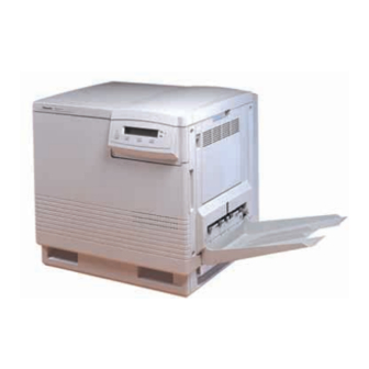
(FRU) list and assembly/disassembly procedures for selected FRUs. To ensure complete understanding of the product, we recommend participation in Phaser 560 service training. 9697-01 Figure 1-1 The Phaser 560 Color Printer Service Manual Downloaded from www.Manualslib.com manuals search engine... -
Page 16: The Phaser 560 Color Printer
An additional 22 fonts can be added via an optional snap-in SIMM (which also enables other extended features). The standard Phaser 560 prints at a resolution of 600 x 600 dots-per-inch. The addition of the extended feature (font) SIMM allows the printer to print at higher resolutions 1200 x 1200 (Premium mode) dots per inch. -
Page 17: Ram And Printer Capabilities
General Information After being idle for the selected amount of time the printer switches into its Energy Star mode where it consumes less than 45 watts of power. It “awakens” upon receiving data at any of its ports. Print speeds depend on the chosen resolution and selected media. For resolutions of 600 x 600 (standard), in color, the printer prints at 3.5 pages per minute (ppm) on paper. -
Page 18: Print Engine Assemblies
(right door) Paper feeder Black toner cartridge Cyan toner cartridge Magenta toner cartridge Yellow toner cartridge Pre-transfer lamp Fuser Paper tray 9697-02 Figure 1-2 Print engine major components Phaser 560 Color Printer Downloaded from www.Manualslib.com manuals search engine... -
Page 19: Figure 1-3 Print Engine Components (Continued)
General Information Ozone fan Toner cartridge drive unit High voltage Toner board cartridge Image motor processor board Power supply unit Engine control board Fuser fan Cleaning board Paper feed motor Interconnect Main motor board Temperature/ humidity Lower door open sensor board sensor 9697-03 Figure 1-3 Print engine components (continued) -
Page 20: Figure 1-4 Print Engine Sensor, Switch And Solenoid Locations
Figure 1-4 Print engine sensor, switch and solenoid locations The photoconductive belt position sensor is not illustrated. This optical sensor marks the home position of the photoconductive belt. It is mounted inside the customer-replaceable imaging unit. Phaser 560 Color Printer Downloaded from www.Manualslib.com manuals search engine... -
Page 21: Front Panel
General Information Front panel These front panel features are found on the printer: A two-line, 24-character LCD and two LEDs Four push buttons The LCD serves two purposes: displaying current controller and print engine status information and displaying an interactive menu. Status information includes controller status such as Ready , Receiving data and Printing . -
Page 22: Figure 1-5 The Front Panel And Its Functions
Section 6 topic, “Error messages” on page 6-17. Power Error Exit Exit Button 1 Button 2 Button 3 Button 4 9013-06 Figure 1-5 The front panel and its functions Phaser 560 Color Printer Downloaded from www.Manualslib.com manuals search engine... -
Page 23: Rear Panel
General Information Rear panel Connectors The rear panel of the Phaser 560 printer features the host interface connectors to the printer. It includes the following connectors: Bi-directional parallel (high-density connector). SCSI high-density connector (hard disk drive or Phaser CopyStation only). -
Page 24: Figure 1-6 The Phaser 560 Rear Panel
The figure below illustrates the rear panel. Smart card slot for network card RS-232 serial LocalTalk Option Option Option Parallel Health light SCSI 9697-05 Figure 1-6 The Phaser 560 rear panel 1-10 Phaser 560 Color Printer Downloaded from www.Manualslib.com manuals search engine... -
Page 25: Network Card Leds
General Information Network card LEDs The Ethernet network card has two LED indicators: TX indicator (yellow); blinks while data is transmitted to the host. The LED is off while no data is being sent. Twisted Pair (10baseT). RX indicator (green); blinks while the network card is receiving data. -
Page 26: Health Led
Letter (A-size) paper Closed Closed Open Letter (A-size) transparency film Open Open Closed Metric Letter (A4-size) paper Closed Open Closed Metric Letter (A4-size) transparency film Open Closed Open Legal size paper 1-12 Phaser 560 Color Printer Downloaded from www.Manualslib.com manuals search engine... -
Page 27: Figure 1-7 Tray Switch Sensors And Actuators
General Information Sensor actuators Middle Left Right Tray sensors 9013-40 Figure 1-7 Tray switch sensors and actuators 1-13 Service Manual Downloaded from www.Manualslib.com manuals search engine... -
Page 28: Specifications
Bottom: No obstruction under printer that could block its cooling vents. Mounting surface Within 2 degrees of horizontal with all four feet in contact with flatness: the table surface. 1-14 Phaser 560 Color Printer Downloaded from www.Manualslib.com manuals search engine... -
Page 29: Table 1-5 Functional Specifications
General Information Table 1-5 Functional specifications Characteristic Specification Printing process Electro-photographic, four color (CMYK) transfer printing Color medium Four toner cartridges each contain one of four colors: cyan, magenta, yellow or black. The toner is a nonmagnetic, monocomponent contact medium. Addressability Standard, Fast Color and Presentation mode: 600 x 600 dots-per-inch text and graphics... -
Page 30: Table 1-6 Electrical Specifications
30 g, trapezoidal flared pulse, 20 msec each axis. Acoustic Noise Average sound level (LEQ) is less than 53 dbA. Peak noise in (operating) standby mode is 47 dbA. 1-16 Phaser 560 Color Printer Downloaded from www.Manualslib.com manuals search engine... -
Page 31: Regulatory Specifications
General Information Regulatory specifications The printer is a recognized component in conformance with the following regulatory standards: The packaged product meets ASTM D4169-86 and ASTM D4728-87 Transportation Standards. Listed UL 1950 Information Processing and Business Equipment. Certified CSA C22.2 No. 950 Safety of Information Technology Equipment, Including electrical Business Equipment. - Page 32 Downloaded from www.Manualslib.com manuals search engine...
-
Page 33: Installing The Printer And Drivers
Drivers This chapter discusses installing the printer and its drivers as a part of the S0 printer installation option. Tektronix Service Option S0 consists of three main functions detailed in this and the next two chapters of this manual: Chapter 2 “Installing the Printer and Drivers.” The first portion of installation instructions, this chapter, consists of five basic processes:... -
Page 34: Pre-Install Questions For Customers
Will the application(s) and sample files be available at the time of the installation to send test files to the printer?________ Will a SCSI font disk be installed on the printer? ______________________________________ Phaser 560 Color Printer Downloaded from www.Manualslib.com manuals search engine... - Page 35 _______ Swiss Option A5 (161-0154-00) Customers must provide the particular interface cable they need to use with the printer. Customers can purchase the following from the Tektronix Graphics Supplies Order Desk by calling 1-800-835-6100. Parallel cable, DB25 male to Centronics 1284C 012-1468-00 Serial, 9-pin to 9-pin, 3 m (10 ft.), null modem...
- Page 36 750 kbyte hard disk space for files Based on the results of the pre-install interview with the customer, you may wish to access the Tektronix web page www.tek.com/Color_Printers. The support web pages contain the latest software, drivers and installation guides.
-
Page 37: Unpacking
Installing the Printer and Drivers Unpacking Printer inventory Power cord User manual Quick Start installation instructions Product registration and licence agreement Quick Reference Guide with Color Density Sample Supplies information sheet CD and diskettes with drivers and utilities Optional Phaser Share network user manual and diskettes Four toner cartridges (cyan, magenta, yellow and black) Parallel port cable adapter Note... -
Page 38: Figure 2-1 The Phaser 560 And Its Packaging
Installing the Printer and Drivers 9697-45 Figure 2-1 The Phaser 560 and its packaging Phaser 560 Color Printer Downloaded from www.Manualslib.com manuals search engine... -
Page 39: Setting Up The Printer
Setting up the printer Installing SIMM memory The standard configuration for a Phaser 560 includes 8 Mbytes of memory. Two optional SIMMs can be added for a total of 72 Mbytes of memory. The optional SIMM installation order is as follows:... -
Page 40: Cabling The Printer
Turn off the printer. EtherTalk protocol requires you to attach the Ethernet cable with the printer powered off. Attach the network cable (ThinNet or TwistedPair) to the printer’s appropriate Ethernet connector. Use only one connector. Phaser 560 Color Printer Downloaded from www.Manualslib.com manuals search engine... -
Page 41: Connecting The Printer To A Pc
Turn on the printer. Networked connection using the Token ring port Note For Token Ring networks, the Phaser 560 must have the Option P4 Token Ring Network Card installed. Turn off the printer. Connect the interface cable to the printer’s appropriate Token Ring connector. -
Page 42: Connecting The Printer To A Workstation
Turn on the printer. Networked connection using the Token Ring port Note For Token Ring networks, the Phaser 560 must have the optional Token Ring network card installed. Turn off the printer. Ensure the transmission speed jumper on the printer’s Token Ring network card is set for the speed of the token ring network. -
Page 43: Connecting An Optional Scsi Hard Disk Drive To The Printer
SCSI cable SCSI drive 9697-38 Figure 2-2 Connecting a SCSI hard disk drive to the Phaser 560 Select the desired SCSI address to 1, 2, 3 or 4 on the SCSI drive. The printer’s SCSI address is 7. Turn on the disk drive first, and then turn on the printer. -
Page 44: Connecting The Optional Copystation To The Printer
Attach the other end of the SCSI cable to the CopyStation’s SCSI port. CopyStation SCSI cable 9697-39 Figure 2-3 Connecting a CopyStation to the Phaser 560 Turn on the CopyStation (and any hard drives) first, and then turn on the printer. Refer to the Phaser CopyStation User Manual for details. -
Page 45: Turning On The Printer
Ports (serial, parallel, LocalTalk, Ethernet, Token Ring) Ethernet protocols available TekColor corrections and print quality mode Pages printed Amount of RAM installed Tektronix version firmware level Print engine firmware level Adobe version software level Printer SCSI ID Authorization code SCSI disk attached... - Page 46 Color settings such as FinePoint and Vivid Color. Serial port settings Parallel port settings LocalTalk port settings EtherTalk settings Token Ring settings TCP/IP settings Novell NetWare settings Table 2-1 Configuration page settings for the Phaser 560 Parameter Description Saved Default Limits or alternate choices NVRAM Printer type The name of the product.
- Page 47 Installing the Printer and Drivers Table 2-1 Configuration page settings for the Phaser 560 (cont'd.) Parameter Description Saved Default Limits or alternate choices NVRAM Fonts in ROM Number of font stored in the printers ROM memory. Job Timeout Amount of time a job can take to 0 seconds Any value denoted in seconds.
- Page 48 Installing the Printer and Drivers Table 2-1 Configuration page settings for the Phaser 560 (cont'd.) Parameter Description Saved Default Limits or alternate choices NVRAM Average Black Average per page toner coverage (%) for toner coverage the current toner cartridge Average Cyan...
- Page 49 Installing the Printer and Drivers Table 2-1 Configuration page settings for the Phaser 560 (cont'd.) Parameter Description Saved Default Limits or alternate choices NVRAM Boot Delay Number of seconds the printer waits Any positive integer before booting up the attached hard drive.
- Page 50 Installing the Printer and Drivers Table 2-1 Configuration page settings for the Phaser 560 (cont'd.) Parameter Description Saved Default Limits or alternate choices NVRAM Connection Indicated if the printer is connected or Inserted No Cable, Cable connected, State inserted into the token ring.
- Page 51 Installing the Printer and Drivers Table 2-1 Configuration page settings for the Phaser 560 (cont'd.) Parameter Description Saved Default Limits or alternate choices NVRAM Broadcast The IP Address used to broadcast Default String of 15 or fewer Address messages on the local network. If null,...
- Page 52 Installing the Printer and Drivers Table 2-1 Configuration page settings for the Phaser 560 (cont'd.) Parameter Description Saved Default Limits or alternate choices NVRAM Log Priority The threshold indicating the priority level 0 – unit is no longer usable, of messages from the printer that will be 1 –...
-
Page 53: Driver And Communication Set Up
Insert either the printer’s CD-ROM or the first Macintosh diskette into the appropriate drive on your computer. Double-click the Phaser 560 Installer icon. Click Continue until the Easy Install window appears. Select Easy Install or Custom Install: For Easy Install Click Install. -
Page 54: Setting Up The Phaser 560 Printer Driver
Select Chooser from the Apple menu after installing the printer’s software. Click on the icon of the Phaser 560 printer driver (on the left side of the Chooser). Click on the Zone for your printer. See your network administrator if you have questions. -
Page 55: Setting Up The Phaser 560 Gx Printer Driver
Select Chooser from the Apple menu after installing the printer’s software. Click on the icon of the Phaser 560 GX printer driver (on the left side of the Chooser). Click on the Zone for your printer. See your network administrator if you have questions. -
Page 56: Installing A Printer Driver For Microsoft Windows 95
For best performance and added features when printing from Windows 95, use the Windows 95 printer driver (as opposed to the Windows 3.1 printer driver, which may cause printing problems in Windows 95). The Phaser 560 Color Printer User Manual gives the step by step procedure you follow to perform this configuration. - Page 57 Extended Features: Yes or No. Select the port the printer is connected to, and click Next. Enter a name for the printer, and select the Phaser 560 as the default printer if desired, and click Next. Decide if you want to print a test page, Yes or No, and click Finish.
-
Page 58: Installing Printer Software For Windows
Add Printer Wizard again. In the Add Printer Wizard, click Next in the opening dialog box. Select printer management, either My computer or Network printer server, and click Next. 2-26 Phaser 560 Color Printer Downloaded from www.Manualslib.com manuals search engine... - Page 59 If you are not sure of the printers’s version, check the printer’s startup page for Extended Features: Yes or No. Enter a name for the printer, and select the Phaser 560 as the default printer if desired, and click Next.
-
Page 60: Installing Printer Software For Windows Nt 3.51
From the Printer menu select Create Printer. In the Create Printer dialog box, under Driver, select Other. Type in the drive for the printer’s CD-ROM or diskette, click OK. 2-28 Phaser 560 Color Printer Downloaded from www.Manualslib.com manuals search engine... - Page 61 In the Select Driver dialog box, under Printer Driver, select the Phaser 560 printer, and click OK: Tektronix Phaser 560 Extended (Extended Features option) Tektronix Phaser 560 (standard printer configuration) If you are not sure of the printers’s version, check the printer’s startup page for Extended Features: Yes or No.
-
Page 62: Installing Printer Software For Windows 3.1
Note: The Tektronix Printer Driver for Windows 3.1 must be installed in the Windows directory (default Destination Directory). Do not change the Destination Directory when installing the Tektronix driver unless you are installing the driver on a network and you know the location of the Windows directory on the network drive. - Page 63 Go on to the setup instructions. Tektronix Driver for Windows 3.1: Setup instructions If you selected Easy Installation, or if you selected the Tektronix Driver for Windows 3.1 in the Custom Installation, continue with the following instructions: 1. Open the Windows Control Panel.
-
Page 64: Setting Up The Printer On A Network (Windows Nt 3.5 And 3.51)
Configuration Page. If not, ask the network administrator. For Name of printer on that machine, type in one of the following (use capital letters): for PostScript AUTO for automatic selection Click OK to complete the installation. 2-32 Phaser 560 Color Printer Downloaded from www.Manualslib.com manuals search engine... -
Page 65: Appletalk Connection
Select AppleTalk Printing Devices for Available Print Monitors; click Double-click on the appropriate zone (if there are multiple AppleTalk zones). Select the Tektronix printer and click OK. At the prompt Do you want to capture this AppleTalk Printing Device?, click No. -
Page 66: Setting Up The Printer On A Network (Windows Nt 4.0)
TCP/IP protocol on the server. This is done from the Control Panel/Network box. Click on the Protocols tab and click Add. Select TCP/IP Protocol and click OK. To apply these changes, restart the Windows NT 4.0 server. 2-34 Phaser 560 Color Printer Downloaded from www.Manualslib.com manuals search engine... - Page 67 Recommended Do not print a Test Page Insert the Tektronix CD-ROM into the computer’s CD-ROM drive. Type in the path name to the requested files, then click OK. If you printed a Test Page, check if it printed; then click OK.
-
Page 68: Workstation Software - Downloadable Printer Utility Files
Look in the .bin directory for workstation-specific files. Mount the printer’s PC diskette 1 and copy the files to your workstation’s hard drive. Access the Tektronix anonymous ftp site on the Internet at ftp.tek.com. Download utility files from the Tektronix Bulletin Board Service (BBS). -
Page 69: Setting The Printer's Ip Address Using The Front Panel
PCL or UNIX-host TCP/IP printing. As an alternative you can download the editable PostScript snippet IPconfig.ps to the printer. the snippet is available on the Tektronix web page, bulletin board and the printer’s CD-ROM. -
Page 70: Configuring The Printer's Serial Port For A Pc
{quit} if (%Serial_NV%) <</Password (0) /FlowControl /X0nXoff /Parity /None /DataBits /StopBits /Baud 9600 >> setdevparams false (0) startjob pop CTRL-D Note CTRL-D is the ASCII End-Of-Text (EOT) character. 2-38 Phaser 560 Color Printer Downloaded from www.Manualslib.com manuals search engine... - Page 71 Installing the Printer and Drivers Use a text editor or word processor to modify the DEVPARAMS.PS file. (Be sure to save the file as a text-only file.) Substitute the values you want for the values used in the sample DEVPARAM.PS. The possible values for each parameter are listed in the following table.
-
Page 72: Configuring A Novell Netware 3.X Server For The Printer
The PhaserShare Network Cards and Software System Administrator User Manual gives the step by step procedure you follow to perform this configuration. Also refer to the Tektronix web pages www/tek./com/Color_Printers/userdocs for the latest install information. There are two methods, each using a different utility program, you can use to configure the file server and set up print queues. -
Page 73: Configuring Netware 4.1 In A Windows Environment
Installing the Printer and Drivers Configuring NetWare 4.1 in a Windows environment Note This procedure describes NetWare 4.1 configuration using the NWAdmin utility. You can also perform network configuration using PCONSOLE, refer to the PhaserShare Network Systems Administrator manual. If you are running the printer in bindery emulation mode, use PCONSOLE to configure the network. -
Page 74: Configuring Tcp/Ip On A Unix Host
Add the printer name to the host table (/etc/host) and assign an IP address to the printer’s name. Assign a print queue to the printer. If necessary, refer to the Tektronix web page http://www.tek.com/Color_Printers/userdoc/PShare3/ tcpunix.html”, for the latest information on host-specific, TCP/IP configurations. - Page 75 Installing the Printer and Drivers Configuring the printer Set the printer’s IP address as described in the earlier topic "Setting the printer’s IP address using the front panel” on page 2-37. Alternately, you can create a RARP or BOOTP configuration file to automatically configure the printer’s IP address (although it will not be stored in the printer’s NVRAM).
- Page 76 Downloaded from www.Manualslib.com manuals search engine...
-
Page 77: Verifying The Printer And Host Connections
Chapter Verifying the Printer and Host Connections In this chapter, you verify that the host computer can send files to the printer. This chapter assumes that the printer and the printer drivers have been properly installed as explained in the previous chapter, “Installing the Printer and Drivers.”... -
Page 78: Windows 3.1 Driver Verification
Type in a line of text such as THIS IS A TEST . Click the File menu item and select Printer Setup... from the menu list. Select Phaser 560 , (whichever applies) from the displayed list of available printer drivers. Click OK . -
Page 79: Novell Netware Verification
(Point to any printer object, click the right mouse button, click on Select Default , and click on Phaser 560.) This is a simple way to be sure that all printers are set up correctly. -
Page 80: Using The Error Handler Utility
Send a file to the printer as explained in the previous procedure. If an error occurs, the printer will print a page listing the error. Phaser 560 Color Printer Downloaded from www.Manualslib.com manuals search engine... -
Page 81: Verifying Printing From A Macintosh
Displayed on the right side of the dialog box are a list of printers that the selected driver will print to. Select the newly installed printer Phaser 560. (If, for example, a Phaser 560 printer is already on the network with the name Phaser 560, then the newly installed printer will be named Phaser 560-1.) -
Page 82: Printing The Directory From A Macintosh
(such as both LocalTalk and Ethernet). Refer to Chapter 6, “Troubleshooting” for more information about networks. More troubleshooting tips are included in the reference manual Phaser 560 Drivers and Utilities Printing Reference. Printing the directory from a Macintosh Make sure that you have an open window displayed on the screen (such as the hard disk drive's window). -
Page 83: Using The Error Handler Utility
If problems occur at this point, download the error handling utility to the printer as explained in the next procedure. Contact the Customer Support Hotline at 1-800-835-6100. Refer to the Phaser 560 User Manual. Each provides information on using the printer with specific applications. -
Page 84: Verifying Printing From A Workstation
Verifying printing from a workstation Verifying and printing using the TCP/IP protocols The Phaser 560 accepts files from networked UNIX and VMS workstations using TCP/IP communications. The printer supports BSD UNIX 4.3, AT&T's UNIX System V with BSD 4.3 lpr extensions, and DEC VMS with Tektronix PhaserSym software or equivalent. -
Page 85: Using The Error Handler Utility
Verifying the Printer and Host Connections To print to the Phaser 560 printer in the VMS environment, you must have the symbiont PhaserSym or equivalent running on the host. To print to the printer from the host, you must first have the printer’s queue established. This is site-dependent and requires the aid of the site’s network administrator. - Page 86 Downloaded from www.Manualslib.com manuals search engine...
-
Page 87: Key Operator Training
Chapter Key Operator Training This chapter covers the last portion of the Tektronix Service Option S0 installation: training the printer's key operator. The steps you follow here place an emphasis on encouraging the key operator to read and use the printer's customer manual and to clean and care for the printer. -
Page 88: Printer Controls And Indicators
(28 lb) papers will tray feed without problems. However, jamming is more likely if the prints are output in face-down mode. Face-up output should be used with heavy stock paper for the best reliability. Phaser 560 Color Printer Downloaded from www.Manualslib.com manuals search engine... - Page 89 Key Operator Training Follow these guidelines when you make transparencies: Use only Tektronix transparencies . When using the tray, load the transparencies so that the notched end of the transparency is in the lower-right corner of the tray. The notched end should be next to the load level decal inside the tray, near the paper backstop.
-
Page 90: Customer-Replaceable Consumables
Don’t touch the roller. Also , d on’t touch end of the roller shaft, it is coated with an electrically-conductive grease. Explain to the customer how to remove and install the transfer roller. Phaser 560 Color Printer Downloaded from www.Manualslib.com... -
Page 91: Fuser
Key Operator Training Fuser Warn customers of the hot rollers on the side of the fuser. Demonstrate how to properly handle and install the fuser and the fuser roll. Warn customers not to interchange fusers rolls between fusers. It “confuses” the printers counters and can ultimately damage the fuser. Fuser roller Demonstrate how to properly change the fuser’s fuser roll. -
Page 92: Clearing Paper Jams
Show where this is explained in the user manual and quick reference guide. Demonstrate how to remove the fuser and the fuser roll to remove a jam wrapped around the fuser roller. Ensure that all paper is removed from the fuser. Phaser 560 Color Printer Downloaded from www.Manualslib.com manuals search engine... -
Page 93: Warranty Information
The customer fills out the agreement and attaches a copy of the invoice or shipping memo for the printer and sends the agreement to Tektronix within 90 days of printer shipment. This starts the service agreement, its duration dating from the printer ship date. -
Page 94: If You Need Help
Key Operator Training If you need help If a customer needs assistance, have then contact a local Tektronix dealer or sales representative or any of these listed resources: Type of service How to access Details Customer Support Hotline U. S. and Canada 1-800-835-6100... -
Page 95: Receiving Email Update Notices
Receiving email update notices Using the World Wide Web, you can register to receive email notification of new printer drivers, accessories and upgrades for your Tektronix Phaser color printer as they become available. To subscribe to this free service, simply follow these... -
Page 96: Using The Automated Fax Systems
Using the automated fax systems As an alternative to other resources, and to provide up-to-date information quickly, Tektronix has set up HAL (Highly Automated Library) and EuroHAL, two interactive, automated fax systems. These automated fax systems provide Macintosh, PC, and workstation users with the latest technical hints and tips... -
Page 97: Customer Support Hotline
Customer Support Hotline). Open Monday through Friday 6:00 am to 5:00 pm (PST). Service support If the printer needs service, customers should contact their Tektronix service representative at 1-800-835-6100 in the United States. Customers should be prepared with the printer type, serial number and, if applicable, print samples revealing the problem. - Page 98 Downloaded from www.Manualslib.com manuals search engine...
-
Page 99: Theory Of Operation
Chapter Theory of Operation Overview This section covers the theory of operation of each subsystem within the printer: Functional block diagram Imaging Fusing The paper path The power supply The image processor Service Manual Downloaded from www.Manualslib.com manuals search engine... -
Page 100: Functional Block Diagram
The laser scanner The laser scanner is the device that “writes” the image onto the imaging unit’s photoconductive belt. Phaser 560 Color Printer Downloaded from www.Manualslib.com manuals search engine... - Page 101 Theory of Operation The toner cartridges Four toner cartridges, black, yellow, cyan and magenta, contain the primary color toners. Each toner cartridge feature a voltage-biased developer that sequentially transfers that cartridge’s toner onto imaging unit’s photoconductive belt depending on where the laser exposed the belt. Subsequently, the toner is transferred to the imaging unit’s accumulator belt from which it is transferred to a sheet of media.
-
Page 102: Laser Imaging
This prevent an image from one print contaminating or ”ghosting” on the next print. The blade only comes in contact with the belt once the accumulated toner layers are transferred to the sheet of paper. Phaser 560 Color Printer Downloaded from www.Manualslib.com... -
Page 103: Figure 5-2 Laser Printing Process Overview
Theory of Operation Laser scanner Photoconductive belt Toner Scorotron developers charger Erase Black lamp Photo conductive Cyan belt cleaner Magenta Yellow First bias transfer roller Pre-transfer Lamp Accumulator Multipurpose Fuser roll Accumulator belt tray pick +500 ~ 700 v belt cleaner roller Take-up Aligning... -
Page 104: Pre-Exposure
“erases” negative charges from the belt. Pre-exposure lamp Light from the Photoconductive pre-exposure belt lamp's (erase lamp's) LEDs removes negative charges from the belt. 9013-13 Figure 5-3 Pre-exposing the photoconductive belt Phaser 560 Color Printer Downloaded from www.Manualslib.com manuals search engine... -
Page 105: Electrostatic Charging
Theory of Operation Electrostatic charging The electrostatic potential of the belt is not uniform following pre-exposure. As the belt rotates, it passes a scorotron charger which bombards the belt with negative charges. The scorotron charger behaves somewhat like a vacuum tube. The grid of the charger, held at a potential of between -500 volts to -540 volts and coupled with the varying voltage potential on any discrete point on the belt’s surface, determine how many electrons can flow from the corona wire onto that... -
Page 106: Laser Exposure
-540 volts (unexposed) to -10 or -20 volts (fully exposed). Laser scanner The laser beam selectively neutralizes some of the negative charges on the belt surface. 9013-15 Figure 5-5 Laser exposure of the photoconductive belt Phaser 560 Color Printer Downloaded from www.Manualslib.com manuals search engine... -
Page 107: The Laser Scanner
Theory of Operation The laser scanner Lenses and mirrors in the laser scanner direct the beam at the photoconductive belt. The beam originates at a laser diode. The beam is made parallel by the collimator lens and is directed at the rotating polygonal mirror. The mirror rotates at a constant 23,000 revolutions per minute. -
Page 108: Toner Pickup (Development)
The doctor blade smooths and evens out the toner on the developer roller. Also inside the toner cartridge are gear-driven paddles the churn the toner and keep it fluidized and moving towards the developer roller. 5-10 Phaser 560 Color Printer Downloaded from www.Manualslib.com manuals search engine... -
Page 109: Toner Transfer To The Accumulator Belt
Theory of Operation Toner transfer to the accumulator belt As the photoconductive belt rotates, it comes in contact with the accumulator belt, which rotates at the same speed. The first bias transfer roller, located under the accumulator belt at the contact point with the photoconductive belt, carries a charge which varies between +500 and +700 volts based on the sensed temperature, humidity, and print speed. -
Page 110: Paper Picking
Figure 5-9 Paper picking A similar pick and feed operation takes place in the optional lower tray assembly to pick and feed the sheet into the printer’s intermediate rollers. 5-12 Phaser 560 Color Printer Downloaded from www.Manualslib.com manuals search engine... -
Page 111: Toner Transfer To Paper
Theory of Operation Toner transfer to paper Once all four layers of toner have been picked up on the accumulator belt, The aligning roller clutch is energized to advance a sheet of paper (which has already been picked) to the second bias transfer roller. (In the user manual the second bias transfer roller is referred to as the transfer roller , a customer-replaceable consumable item.) The movement of the sheet of paper is timed so that the leading edge of the toner image on the accumulator belt meets with the paper... -
Page 112: Fusing And Exiting
Output tray roller full sensor Supply roller Pressure roller Fuser Paper exit entrance sensor sensor Output tray Fuser Heated roller 9697-36 Figure 5-11 Fusing the toner to the paper 5-14 Phaser 560 Color Printer Downloaded from www.Manualslib.com manuals search engine... -
Page 113: Print Modes
Theory of Operation Print modes The printer features five print modes: Presentation, Fast Color, Standard, and Premium. Standard, Presentation and Fast Color mode are performed using 600 x 600 dpi printing. Premium mode is 1200 x 1200 dpi printing. If no motion were involved, the laser dot produced would be an ovoid shape, measuring about 50 microns wide by 55 microns tall. -
Page 114: Printer Color Correction
Quick Reference Card and entering value changes through the front panels. This process is described in the Phaser 560 Color Printer User Manua l and well as in the Chapter 9 topic, “Manually setting color corrections”... -
Page 115: Low Voltage Power Supply
Theory of Operation Low voltage power supply The low voltage power supply generates five DC voltages: +5 VDC for the image processor and the engine control logic. Fuses F352 and F353 are provided for short protection. +24 VDC for the motors, high voltage board and the cams, clutches and solenoids. -
Page 116: Image Processor Board
The control loop also monitors the control and error signals fed back from the print engine. 5-18 Phaser 560 Color Printer Downloaded from www.Manualslib.com manuals search engine... -
Page 117: Figure 5-14 The Image Processor Graphics Pipeline
Theory of Operation Control loop PostScript Rasterizer Engine Parallel Print interpreter driver engine serializer SCSI Ethernet Network Serial card Fonts in LocalTalk Image processor 9013-58 Figure 5-14 The image processor graphics pipeline 5-19 Service Manual Downloaded from www.Manualslib.com manuals search engine... - Page 118 Downloaded from www.Manualslib.com manuals search engine...
-
Page 119: System Power-Up Sequence
Chapter Troubleshooting This chapter discusses troubleshooting the printer. Troubleshooting is discussed with two approaches: A step-by-step verification procedure that systematically confirms that particular components of the printer are properly functioning until a problem is found. A symptom/cause scheme that lists particular printer failures and error codes and their possible causes. -
Page 120: Print Engine Troubleshooting
6-3. If the printer does not make the test print, then a problem exists with the printer. Proceed with the topic, “Verifying power supply operation” on page 6-3. Phaser 560 Color Printer Downloaded from www.Manualslib.com manuals search engine... -
Page 121: Verifying Printer Operation By Using Its Self-Test Print
Troubleshooting Verifying printer operation by using its self-test print If not already on, turn on the printer. If the printer does not power up, or does not initialize, or the printer initializes but the motors do not run properly, go to the next topic “Verifying power supply operation.” When the Ready message is displayed, press the Menu button to enter the menu. -
Page 122: Figure 6-1 Measuring The Dc Voltages (Test Points)
The 115 VAC power supply features a 10 A and 6.3 A fuse. The 220 VAC power supply fuse uses an 6.3 A fuse. Turn off the printer. Remove the power supply as explained in the Chapter 8 topic, “Power supply” on page 8-15. Phaser 560 Color Printer Downloaded from www.Manualslib.com manuals search engine... -
Page 123: Safety Interlocks
Troubleshooting As explained in the Chapter 8 topic, “Power supply fuse” on page 8-16, remove the power supply cover to access the fuse. Visually, and with a VOM, check to determine that the fuse is in working order. If the fuse is good, but the printer's power supply does not output DC voltages, proceed to the next topic, “Testing for a shorted motor.”... -
Page 124: Figure 6-2 Door Safety Interlock Switches
If the motors and solenoids are functional, but the power supply still does not function, replace it. Refer to the Chapter 8 topic, “Power supply” on page 8-15. Phaser 560 Color Printer Downloaded from www.Manualslib.com... -
Page 125: Media Jams And The Paper Path
Troubleshooting Media jams and the paper path Required tools #1 Phillips screwdriver Jams fall into the following four categories: Media-based problems Paper-picking errors Printing jams Paper-ejecting errors Media-based problems Media problems Check that the correct type of media is being used. The customer should be using a quality laser printer paper. -
Page 126: The Media Skews Passing Through The Paper Path
Is the paper feeder’s wiring harness properly connected to the engine control board (CN20)? (For the Lower Tray Assembly, check connector CN19). Inspect the wiring harness for defects. Replace the paper feeder. Replace the engine control board. Phaser 560 Color Printer Downloaded from www.Manualslib.com manuals search engine... -
Page 127: No Paper Feeder Installed
Troubleshooting No paper feeder installed Check to see if the paper feeder is properly installed in the printer and making good electrical contact. Push it in all the way. Ensure that the wiring harness leading from the paper feeder to the engine control board is properly installed in connector CN20. -
Page 128: Paper Jams Midway In The Paper Feeder
The spring tension should measure about 65 grams when the roller end is in the middle of its travel in its slot. 6-10 Phaser 560 Color Printer Downloaded from www.Manualslib.com manuals search engine... -
Page 129: Fuser Jams
Troubleshooting Clean the aligning rollers. Do the aligning rollers rotate during a paper pick? Determine if the aligning roller clutch operates correctly. Check that the paper feeder wiring is properly installed and that the wiring harnesses are not damaged. Check the spring pressure at each end of the aligning rollers. Lifting each end of the roller with a tension gauge should reveal a measurement of about 1 kg (2.2 lbs). -
Page 130: Eject Jams
Is the multi-purpose feed sensor empty flag properly interrupting the multi-purpose pick sensor? Check the wiring harness between the multi-purpose sensor circuit board and the paper feeder board (connector CN607). Ensure that the wiring harness is not damaged. 6-12 Phaser 560 Color Printer Downloaded from www.Manualslib.com manuals search engine... -
Page 131: Other Problems
Troubleshooting Check the wiring harness leading from the paper feeder to the engine control board (connector CN20). Replace the paper feeder circuit board. Replace the engine control board. Other problems These problems may be indicated as errors on the front panel. The printer continuously displays “Initializing”... -
Page 132: No Fuser Installed When It Is
(with an audible click). Replace the interlock switch. Replace the power supply. Replace the engine control board. 6-14 Phaser 560 Color Printer Downloaded from www.Manualslib.com manuals search engine... -
Page 133: Left-Side Door Open When It Is Not
Troubleshooting Left-side door open when it is not The procedure for troubleshooting this problem applies to the Lower Tray Assembly as well. Is the left door open switch, located in the lower-left back corner of the printer, properly in place? Does closing the left door actuate the left door open switch? Is the left door properly in place? Replace the door if it does not operate correctly. -
Page 134: High Voltage Error
READY and WARMING UP. Make sure all connectors to the circuit boards are well seated and make sure that the screws holding the boards’s in place are tight. 6-16 Phaser 560 Color Printer Downloaded from www.Manualslib.com manuals search engine... -
Page 135: Table 6-1 Print Engine Service Error Codes
Troubleshooting Error messages Generally, the top line of the two-line front panel display indicates the printer’s status, such as Ready, Printing, Busy, or Stopped. The bottom line indicates the function of the three buttons located immediately below the LCD. The front panel also displays error codes when it encounters certain system failures. - Page 136 3. Inspect the wiring harness leading from the accumulator belt position sensor to CN13 of the engine control board. 4. Replace the imaging unit. 5. Replace the accumulator belt position sensor. 6. Replace the engine control board. 6-18 Phaser 560 Color Printer Downloaded from www.Manualslib.com manuals search engine...
- Page 137 Troubleshooting Table 6-1 Print engine service error codes (cont'd.) Error code Meaning of error code and what to do about it Positioning error of the photoconductive belt. 1. Ensure that the imaging unit is properly installed and locked in place. 2.
- Page 138 6. Inspect the wiring harness leading from the paper feed motor to connector CN20 of the engine control board. 7. Replace the paper feed motor. 8. Replace the engine control board. 6-20 Phaser 560 Color Printer Downloaded from www.Manualslib.com manuals search engine...
- Page 139 Troubleshooting Table 6-1 Print engine service error codes (cont'd.) Error code Meaning of error code and what to do about it Main motor lost sync. 1. Is the imaging unit properly installed and locked in position? 2. Do the photoconductive and accumulator belts rotate when driven by the main motor? Manually turn the main drive gears to rotate the belts of the imaging unit.
-
Page 140: Printing And Print Quality Problems
Inspect the scorotron charge (main charger) for a broken corona wire. Replace the scorotron charger. Replace the high-voltage board Margins are white, print is black. Replace the image processor board. Replace the engine control board. 6-22 Phaser 560 Color Printer Downloaded from www.Manualslib.com manuals search engine... -
Page 141: Missing Primary Color
Troubleshooting Missing primary color Replace the toner cartridge of the missing color. Determine if the cartridge selector is pushing the toner cartridges into contact with the photoconductive drum. Check the wiring harness leading from the cartridge selector/eject unit to CN308 of the engine control board. Replace the toner cartridge drive unit. -
Page 142: Repeated Spots Or Lines On Print In-Line With Each Other
White horizontal line or band in all the colors of a print Replace the imaging unit. Replace the second bias transfer roller. Inspect it for loose roller contacts. Grease the end of the roller shaft with conductive grease. 6-24 Phaser 560 Color Printer Downloaded from www.Manualslib.com manuals search engine... -
Page 143: Vertical Lines In The Print
Troubleshooting Vertical lines in the print Inspect the path the laser beam travels for foreign matter that could block the beam from striking the photoconductive belt. Check the main charger wire and grid. White streaks are caused by a dirty grid. Black streaks are caused by a dirty wire. If the line is colored, one toner cartridge may not be outputting toner correctly. -
Page 144: Ghosting
Empty the waste bin of the second bias transfer roller. Clean the paper path of the paper feeder. Inspect the fuser rollers for contamination. Replace the fuser. Replace the paper feeder. 6-26 Phaser 560 Color Printer Downloaded from www.Manualslib.com manuals search engine... -
Page 145: No Printing On Edge Of Print
Troubleshooting No printing on edge of print If one primary color is missing, replace that color’s toner cartridge. Check that each toner cartridge moves forward smoothly toward the imaging unit. Also inspect the two metal pads on the ends of the toner cartridge that the toner cartridge selector cams push against. -
Page 146: Macintosh Printing Problems
In the print dialog box, make sure that the Color/Grayscale option has been selected. Make sure that the Phaser 560 icon was selected in the Chooser. Try printing the job again. Check the version of your LaserWriter driver to ensure that it is version 6.0.x or higher. -
Page 147: Image Is Rotated 90 Degrees
Troubleshooting The application may require special instructions to print, such as those contained in a.PPD file. Check in the Phaser 560 Drivers and Utilities Printing Reference or the disk readme files. Image is rotated 90 degrees In the application's Page Setup, make sure that the image is selected to print in portrait or landscape orientation as you expect. - Page 148 PRINT button to print an internal test print. Is the printer in PostScript mode? Check this by printing the configuration page. Refer to Phaser 560 Drivers and Utilities Printing Reference for complete instructions on sending a utility file to the printer to set the port to PostScript mode.
-
Page 149: Windows Printing Problems
(CMY), blue is often printed as purple. To adjust blue from within Microsoft Windows: Within the Tektronix PostScript Windows driver you have an option, Vivid Color, that alters the blue colors that are appearing purple. -
Page 150: Workstation Printing Problems
file. Use a text editor to open and examine the file. From the Utilities diskette, use the utility file add-ctrl-D to add a CTRL-D to the end of the file. Then send the file to the printer. 6-32 Phaser 560 Color Printer Downloaded from www.Manualslib.com manuals search engine... -
Page 151: Service Preventive Maintenance Procedure
Chapter Cleaning and Maintenance Service preventive maintenance procedure Whenever you check, service, or repair a printer, you should perform the following procedures. Cleaning the printer, as outlined in the following steps, assures proper operation of the printer and reduces the probability of having to service the printer in the future. -
Page 152: Recommended Tools
Clean the laser window with puffs of air from the suction bulb. Alternately, you can vacuum the window clean. Wipe off the pre-exposure lamp bezel and the pre-transfer lamp bezel with a lint-free wipe. Vacuum out the interior of the printer. Phaser 560 Color Printer Downloaded from www.Manualslib.com manuals search engine... -
Page 153: Lubrication
Cleaning and Maintenance Carefully clean the area around the second bias transfer roller’s cleaning roller for impacted toner. Remove the second bias transfer roller Tap on the cleaning roll cover to knock the toner loose from that area. Vacuum the toner. Lubrication Molybdenum-based (brown) grease, part number 006-7436-00 For all metal-to-metal, metal-to-plastic, and plastic-to-plastic gears. - Page 154 Downloaded from www.Manualslib.com manuals search engine...
-
Page 155: Required Tools
Chapter Disassembly/Assembly This chapter explains how to remove and replace many of the printer's Field Replaceable Units (FRUs). This chapter covers procedures for FRUs that are difficult to remove or require special handling or precautions. Refer to Appendix A for a list of the printer's FRUs. Required tools Magnetic tip screwdrivers;... -
Page 156: The Printer Cabinet
Tilt forward and remove the cover. Multi-purpose feeder tray. Tilt the tray up slightly and squeeze the tray’s retaining pins inward to free it from the print engine frame. Phaser 560 Color Printer Downloaded from www.Manualslib.com manuals search engine... -
Page 157: Figure 8-1 Removing Cabinet Covers
FRU Disassembly/Assembly Top cover Hinge frame Conical spring Hinge pin Door Upper rear cover Retainer hooks Left side cover Manual feed tray Left door Lower rear cover 9697-08 Figure 8-1 Removing cabinet covers Service Manual Downloaded from www.Manualslib.com manuals search engine... -
Page 158: Front Door
Remove the top cover. Remove the imaging unit. Cover the imaging unit to protect its photconductive belt from light. Remove the three screws securing the toner level sensor board. Disconnect the sensor board’s wiring harness. Remove the sensor. Phaser 560 Color Printer Downloaded from www.Manualslib.com manuals search engine... -
Page 159: Figure 8-2 Removing Cabinet Covers
FRU Disassembly/Assembly Right side covers (front, rear and lower) Remove the lower front cover and the front and rear right side covers before removing the right side lower cover. Remove the paper tray. Note Note that the lower side cover clips underneath the printer frame. Lift the printer slightly to remove the lower side cover in the next step. -
Page 160: Figure 8-3 Removing The Emi Shields
Interconnect wiring shield 9697-10 Figure 8-3 Removing the EMI shields Reverse these steps to install the shields. Ensure that no cables are pinched by the shields as you install them. Phaser 560 Color Printer Downloaded from www.Manualslib.com manuals search engine... -
Page 161: Figure 8-4 Removing The Paper Feeder And The Paper Tray Sensor Board
FRU Disassembly/Assembly Paper feeder Caution Do not tip the paper feeder or flip it over. Waste toner will spill out. Turn off the printer. Open the left side door to access the paper feeder. Slide it out. With a screwdriver, back out the slide rail stop screws. There is one screw at the end of each slide rail. -
Page 162: Multi-Purpose Tray Pick Roller
You may need to use a small flat-blade screw driver to release the retainers hook from the groove in the shaft it locks into. Phaser 560 Color Printer Downloaded from www.Manualslib.com manuals search engine... -
Page 163: Figure 8-5 Removing The Multi-Purpose Tray Pick Roller
FRU Disassembly/Assembly Slide the pick roller 50 mm (2 in.) on its shaft towards the front of the printer. Lift up and remove the pick roller. Latch Pick roller cover Latch Latch Multi purpose tray pick roller Pick roller retainer Retainer groove 9697-42... -
Page 164: Cork Separator Pad
Install a new cork separator pad. Copy count. Use the Service tests discussed in the topic “Printer self-diagnostics” on page 9-6 to reset the cork pad and pick roller’s copy count to zero. 8-10 Phaser 560 Color Printer Downloaded from www.Manualslib.com manuals search engine... -
Page 165: Figure 8-6 Removing The Cork Separator Pad
FRU Disassembly/Assembly Paper guide Retaining hooks Spring Cork separator pad Paper guide 9697-43 Figure 8-6 Removing the cork separator pad Reverse these steps to install the cork separator pad. 8-11 Service Manual Downloaded from www.Manualslib.com manuals search engine... -
Page 166: Cartridge Selector/Eject Unit (Right Door)
(no metal) to move it forward. Unhook the tension springs at each end of the shaft from the engine frame. Note how they fasten to the frame and the right door. 8-12 Phaser 560 Color Printer Downloaded from www.Manualslib.com manuals search engine... -
Page 167: Figure 8-7 Removing The Cartridge Selector/Eject Unit
FRU Disassembly/Assembly Beginning at the rear, remove the cartridge selector/eject unit. Cartridge selector/ eject unit (right door) Remove E-ring and bushing E-ring Keyed bushing Frame Spring Keyed Washer Washer Disconnect wiring harness Remove E-ring Washer Keyed Washer Spring Frame Keyed bushing Remove E-ring and E-ring bushing... -
Page 168: Figure 8-8 Removing The Laser Scanner
Cover the laser window slot leading to the imaging unit to protect the photoconductive belt from room light. Remove three screws Disconnect wiring harnesses Laser scanner these two rnesses to possible 9697-12 Figure 8-8 Removing the laser scanner 8-14 Phaser 560 Color Printer Downloaded from www.Manualslib.com manuals search engine... -
Page 169: Figure 8-9 Removing The Power Supply And The Fuser Installed Switch
FRU Disassembly/Assembly Power supply Remove the upper and lower rear covers and EMI shield as explained in the earlier topic, “The printer cabinet” on page 8-2. Disconnect the three wiring harnesses connected to the power supply. Note for reassembly how the upper wiring harness passes through the cable restrain on the power supply fan. -
Page 170: Figure 8-10 Replacing The Power Supply Fuse
Remove the power supply’s cover. It is secured in place with 7 screws. Locate the fuses near the bottom of the power supply by the power cord receptacle. Fuses 9697-14 Figure 8-10 Replacing the power supply fuse 8-16 Phaser 560 Color Printer Downloaded from www.Manualslib.com manuals search engine... -
Page 171: Figure 8-11 Removing The Engine Control Board
FRU Disassembly/Assembly Printer rear assemblies Note If you are removing the engine control board to access an assembly underneath, it is appropriate to disconnect the board’s wiring harnesses and remove the board and mounting bracket as an assembly. Engine control board Remove the upper rear cover as explained in the earlier procedure, “Upper rear cover”... -
Page 172: Main Motor
Remove the engine control board and bracket as explained in the previous procedure, “Engine control board” on page 8-17. Remove the four screws holding the toner cartridge drive motor in place. Remove the motor. 8-18 Phaser 560 Color Printer Downloaded from www.Manualslib.com manuals search engine... -
Page 173: Figure 8-12 Removing The Main Motor, Paper-Feed Motor, Toner Cartridge Drive Motor And Cleaning Board
FRU Disassembly/Assembly Cleaning board Remove the upper and lower rear covers, and the left side cover as explained in the earlier procedure, “The printer cabinet” on page 8-2. Remove the EMI shields as detailed in the earlier procedure “EMI shields” on page 8-6. Remove the engine control board and bracket as explained in the previous procedure, “Engine control board”... -
Page 174: Toner Cartridge Drive Unit
Move it out of the way. Disconnect the wiring harness leading to the interlock switch. Remove the two screws securing the interlock switch in place. Remove the switch. 8-20 Phaser 560 Color Printer Downloaded from www.Manualslib.com manuals search engine... -
Page 175: Figure 8-13 Removing The Toner Cartridge Drive Unit, Home Position Sensor And The Left Door Interlock Switch
FRU Disassembly/Assembly Toner cartridge drive unit Home position sensor Left door-opened interlock switch Interlock switch cover 9697-17 Figure 8-13 Removing the toner cartridge drive unit, home position sensor and the left door interlock switch 8-21 Service Manual Downloaded from www.Manualslib.com manuals search engine... -
Page 176: Figure 8-14 Removing The Temperature/Humidity Sensor Board
Do not touch the surface of the humidity sensor. Housing Lower rear Temperature/humidity cover sensor board 9697-46 Figure 8-14 Removing the temperature/humidity sensor board Reverse these step to install the temperature/humidity sensor board. 8-22 Phaser 560 Color Printer Downloaded from www.Manualslib.com manuals search engine... -
Page 177: Figure 8-15 Removing The Pre-Exposure Lamp And Pre-Transfer Lamp
FRU Disassembly/Assembly Pre-exposure lamp Turn off the printer. Remove the imaging unit. Remove the screw securing the pre-exposure lamp in place. Disconnect the pre-exposure lamp’s wiring harness. Remove the lamp. Pre-transfer lamp Turn off the printer. Remove the imaging unit. Remove the E-ring securing the front end of the cleaning cam roller. -
Page 178: High-Voltage Board
Disconnect the wiring harness leading to the high-voltage board. Disconnect the high-voltage wires leading from the high-voltage board to the print engine assemblies. Remove the four screws securing the high-voltage board to the printer. Remove the board. 8-24 Phaser 560 Color Printer Downloaded from www.Manualslib.com manuals search engine... -
Page 179: Figure 8-16 Removing The High-Voltage Board
FRU Disassembly/Assembly Wiring harnesses Be careful not to short harness here to nearby screw tip Card cage High-voltage board Cut hazard here 9697-18 Figure 8-16 Removing the high-voltage board Caution When installing the wiring harness retainer, be careful not to press the wiring harness against the tip of a near by screw which will short the harness. -
Page 180: Tray Guides
In the next step, take care not to damage the output tray full sensor flag. Carefully tilt the printer onto its right side. Remove the nine large-head screws securing the bottom pan in place. 8-26 Phaser 560 Color Printer Downloaded from www.Manualslib.com manuals search engine... -
Page 181: Figure 8-17 Removing The Tray Guides
FRU Disassembly/Assembly Remove the two screws securing each tray guide in place. Remove the guide. Bottom pan Tray guides 9697-47 Figure 8-17 Removing the tray guides Reverse these steps to instal the tray guides. 8-27 Service Manual Downloaded from www.Manualslib.com manuals search engine... -
Page 182: Gear Train
Remove the nine large-head screws securing the bottom pan in place. Remove the frame cross member by removing the three screws securing it in place. Remove the two screws securing the gear train restraint in place. 8-28 Phaser 560 Color Printer Downloaded from www.Manualslib.com manuals search engine... -
Page 183: Figure 8-18 Removing The Gear Train
FRU Disassembly/Assembly Remove the gears of the gear train. Gear train Gear train retainer Frame cross member 9697-48 Figure 8-18 Removing the gear train Reverse these steps to install the gear train. 8-29 Service Manual Downloaded from www.Manualslib.com manuals search engine... -
Page 184: Figure 8-19 Installing A Network Card In The Printer
Connect the appropriate host interface cable to the network card. Turn on the printer and print the startup page. It lists the installed memory and options. Network card 9697-24 Figure 8-19 Installing a network card in the printer 8-30 Phaser 560 Color Printer Downloaded from www.Manualslib.com manuals search engine... - Page 185 FRU Disassembly/Assembly Note Whenever you replace the network card, swap the NVRAM chip from the old board to the new board. It is the 8-pin socketed IC. On the Ethernet PhaserShare Card, do not jumper SW1. Otherwise the NVRAM contents will be cleared when the printer is powered-down.
-
Page 186: Figure 8-20 Removing The Image Processor Board
NVRAM IC being swapped. Also, be sure to transfer the RAM SIMMs and extended feature SIMM from the old board to the new board. 8-32 Phaser 560 Color Printer Downloaded from www.Manualslib.com manuals search engine... -
Page 187: Figure 8-21 Installing An Extended Feature Simm
FRU Disassembly/Assembly Installing an Extended Features SIMM Turn off the printer. Do not unplug the printer; this preserves a ground path to dissipate static charges. Remove the image process board from the printer as explained in the earlier procedure “Image processor board” on page 8-32. Insert an Extended Feature SIMM in the Extended Feature SIMM connector labeled J540 and tilt the SIMM down until it locks in place. -
Page 188: Installing Ram Simms
FRU Disassembly/Assembly Installing RAM SIMMs Note The printer only uses Tektronix proprietary 16-Mbyte and 32-Mbytes RAM SIMMs. Installing a second RAM SIMM. If you are installing a second RAM SIMM in the printer, the larger capacity RAM SIMM must be installed in the SIMM 1 connector. -
Page 189: Figure 8-22 Installing Ram Simms
FRU Disassembly/Assembly Print a startup page to check its listing of the printer's memory and options. RAM SIMMs SIMM 1 Image processor board SIMM 2 Insert SIMM and push flat into catch 9697-21 Figure 8-22 Installing RAM SIMMs 8-35 Service Manual Downloaded from www.Manualslib.com manuals search engine... -
Page 190: Figure 8-23 Installing The Code Rom Simm
PostScript ROM SIMM PostScript ROM SIMM connector 9697-23 Figure 8-23 Installing the code ROM SIMM Turn on the printer and print a startup page to check the printer’s performance. 8-36 Phaser 560 Color Printer Downloaded from www.Manualslib.com manuals search engine... -
Page 191: Required Tools
Chapter Checks and Adjustments This chapter discusses using the front panel’s interactive mode to review and change the printer’s operation. It also contains the procedures to calibrate the printer after you replace key Field Replaceable Units and to evaluate the printer's functionality. -
Page 192: Figure 9-1 Menu Map
Cyan Toner TekColor: Vivid Color Service Print 2 Adjust black Magenta Toner TekColor: Display RGB Sampler Prints Yellow Toner Reset Adjustments CMYK Sampler Prints Black Toner Figure 9-1 Menu map Phaser 560 Color Printer Downloaded from www.Manualslib.com manuals search engine... -
Page 193: Figure 9-2 Menu Map (Cont.)
Checks and Adjustments Printer defaults menu Serial settings** Network settings* Language menu Default tray Baud Rate TCP/IP Language: English Upper Baud Rate: 300 Language: Español Interface Middle Baude Rate: 600 Language: Français TCP/IP Address Lower Baud Rate: 1200 Language: Deutsch Network Mask Media Tray Baud Rate: 2400... -
Page 194: Printing Test Prints
Press and hold for 4 seconds the Test Print button in the center of the upper rear cover. This verifies the print engine’s ability to print independent of the image processor. Do not use this print to verify print quality. Phaser 560 Color Printer Downloaded from www.Manualslib.com manuals search engine... -
Page 195: Image Processor Normal Indicators
Checks and Adjustments Image processor normal indicators There are three indications that the print engine and its image processor are powered-up and operating normally: the front panel POWER LED is on (steady), Ready is displayed on the front panel LCD display and the image processor health light is blinking (the flashing health light is viewable through a small hole in the rear panel of the image processor board). -
Page 196: Printer Self-Diagnostics
Pressing and holding Button 1 and 4, as you turn on the printer, allows you to reset the NVRAM to its factory-default values. Refer to the later topic, “Resetting NVRAM” on page 9-12. This also reset the NVRAM of an installed network card. Phaser 560 Color Printer Downloaded from www.Manualslib.com manuals search engine... -
Page 197: Table 9-1 Normal Power Up Error Codes
Checks and Adjustments Normal power-up self-tests. This test requires no paper or customer interaction. If a problem is encountered with the image processor's expansion memory or other options, then the information is printed on the printer's startup page. Normal power-up tests take slightly longer than one minute to complete. Any failure not allowing the printer to print the start page are displayed on the printer’s front panel with a two-digit hex code indicating what the error is. -
Page 198: Table 9-2 Normal Operation Error Codes
Fuser Errors 82 Serial Reply Timeout Error 40 Fuser Low Temperature 83 Illegal Command Error 41 Fuser High Temperature 84 Parity Error 42 Fuser Thermistor Open Error 43 Fuser Rising Temperature Phaser 560 Color Printer Downloaded from www.Manualslib.com manuals search engine... -
Page 199: Table 9-3 Print Engine Service Test Descriptions
Checks and Adjustments Kernel tests. The printer’s image processor executes its core set of CPU tests and then, if no error occurs, goes directly to PostScript initialization. Verification test. This test requires no paper or customer interaction. Disconnect all host cables from the printer before starting the test. A fully configured printer takes slightly longer than 3 minutes to execute the tests. - Page 200 Turns on and off the LEDs of the pre-exposure lamp and the pre-transfer lamp. Remove the imaging unit and override the front door interlock switch to test if all the LEDs of the lamps arrays are lit. 9-10 Phaser 560 Color Printer Downloaded from www.Manualslib.com manuals search engine...
- Page 201 Checks and Adjustments Motors and Fans Main Motor Energizes the main motor until stopped. Override the front door interlock switch Paper Feed Motor Energizes the paper feed motor until stopped. Cartridge Motor Energizes the toner cartridge motor until stopped. Laser Motor Energizes the laser scanner motor until stopped.
-
Page 202: Resetting Nvram
NVRAM parameters will be reset to their factory default values. If you do not press buttons 1 and 3 in the allotted time, the NVRAM will not be changed. 9-12 Phaser 560 Color Printer Downloaded from www.Manualslib.com manuals search engine... -
Page 203: Print Engine Calibration
Checks and Adjustments Print engine calibration Generally, no print engine calibration is required. Usually, if you note a print defect, replacing a toner cartridge, the imaging unit or the transfer roller (or perhaps the paper feeder) corrects the problem. Printer color correction Correcting printer colors is accomplished either semi-automatically or manually. -
Page 204: Figure 9-3 Manual Color Correction Reference Print
Figure 9-3 Manual color correction reference print Overlay and compare the pre-printed primary Color Density Samples in the Phaser 560 Quick Reference Guide to the selected colors on the midline of the print. If any primary color does not match, overlay and compare to an alternate color. -
Page 205: Figure 9-4 Checking The Registration Of The Toner Layers
Checks and Adjustments Checking print registration A simple way to determine if the printer is properly registering (overlaying) the layers of toner is to print and examine the Startup Page. Press the Menu button. With the Help pages menu displayed, scroll to the Startup Page item. - Page 206 Downloaded from www.Manualslib.com manuals search engine...
- Page 207 Field Replaceable Units List This appendix provides a list of field replaceable units for the printer. Changes to Tektronix instruments are made to accommodate improved components as they become available. It is important when ordering parts to include the following information: Component's part number.
-
Page 208: Figure A-1 Cabinet Frus
118-9537-00 Right side cover rear 118-9208-00 Right side cover front 118-9207-00 Right side cover lower 118-9541-00 Bottom front cover 118-9536-00 Output tray (standard) 9697-26 Figure A-1 Cabinet FRUs Phaser 560 Color Printer Downloaded from www.Manualslib.com manuals search engine... -
Page 209: Figure A-2 Cabinet Frus
118-9535-00 Upper rear cover (220 VAC) 118-9528-00 Top cover 118-9542-00 Left side cover 118-9522-00 Multi-purpose feed tray assy 118-9543-00 Left side door assy 334-8366-37 Logo, Phaser 560 9697-27 Figure A-2 Cabinet FRUs Service Manual Downloaded from www.Manualslib.com manuals search engine... -
Page 210: Table A-3 Fru Parts List Of The Exploded Printer
Extended Features SIMM, Kanji Font 671-4147-00 PostScript code ROM SIMM 118-9562-00 Gear kit, paper feeder joint and chassis 118-9563-00 D-roller, paper feed 118-9557-00 Multi-purpose tray kit; roller, spring, pad 118-9558-00 Paper feeder flag kit Phaser 560 Color Printer Downloaded from www.Manualslib.com manuals search engine... -
Page 211: Figure A-3 The Internal Printer
Figure A-3 The internal printer 9697-28 Service Manual Downloaded from www.Manualslib.com manuals search engine... -
Page 212: Table A-4 The Internal Printer
Switch, main power (220 v) 118-9561-00 Lower Paper Tray Assembly circuit board 118-9598-00 Guide, Paper tray, right 070-9698-00 Phaser 560 User Manual (English) 118-9597-00 Guide, Paper tray, left 070-9698-10 Phaser 560 User Manual (French) 118-9560-00 Spring, Toner cartridge, Front and Rear... - Page 213 Table A-5 Supplies and accessories Part number Serial number Quantity Name and description Effective Discontinued 161-0154-00 Power cord, Swiss 161-0240-00 Power cord, Danish 016-1533-00 Transfer Kit (Rubber cover) 118-9070-02 Scorotron main charger, grid unit 006-7998-00 Conductive grease, silicon 006-7971-00 Imaging unit light shield/drape 065-0566-00 Shipping box, replacement kit 039-0029-00...
- Page 214 Downloaded from www.Manualslib.com manuals search engine...
-
Page 215: Test Prints
Appendix Test Prints This appendix illustrates the test prints produced by the print engine. It also illustrates a number of defective prints and the reason for the defects. The Chapter 6 Troubleshooting topic “Printing and print quality problems” on page 6-22 discusses solutions to the problems shown in this appendix. Consumables Print consists of four 25% tint primary color bands and “gas gauges”... - Page 216 (12.1 cm) apart and match the defects on the print, then the problem is a scratch on the fuser roller. Replace the fuser. Lastly a protrusion of some kind in the paper path could be scratching the print. Phaser 560 Color Printer Downloaded from www.Manualslib.com manuals search engine...
- Page 217 Test Prints Dark vertical line in print, single color If the line is of one primary color, then the trouble can usually be traced to a defect in the color’s toner cartridge. Too much toner is transferred from the developer roller to the photoconductive belt at the defect point.
- Page 218 fingerprints and rubbing lightly with a cotton-tipped swab. Don’t remove the toner. The printer will remove the toner with its cleaning blade. Remember not to expose the imaging unit to ambient light for more then a minute. Phaser 560 Color Printer Downloaded from www.Manualslib.com manuals search engine...
- Page 219 Test Prints One or more dark vertical line in all colors This can often be traced to a dirty scorotron charger (main charger) corona wire. Contamination (dust or toner) interferes with the flow of electrons from the wire to the photoconductive drum.
- Page 220 Replace the toner cartridge selector/eject unit. Lastly, poor electro-mechanical contact my be the problem, although this usually shows itself as light, horizontal streaks and lines. Replace the toner cartridge biasing assembly. Phaser 560 Color Printer Downloaded from www.Manualslib.com manuals search engine...
- Page 221 Test Prints Single white spot appear in the same place on the print This indicates a bad spot has developed on the imaging unit’s photoconductive belt which will not transfer toner. The imaging unit must be replaced. If the spot appears to migrate vertically from print to print then the defect is on the imaging unit’s accumulator belt.
- Page 222 6-24. It discusses causes of repeated spots based on the distance between the spots. In some instances, the spots may be dark instead of white. They may also be shaped something other than round. Phaser 560 Color Printer Downloaded from www.Manualslib.com manuals search engine...
- Page 223 Index Adobe PostScript Level 2 1-2 electrically-conductive grease 7-3 all-black print 6-22 engine failure codes 6-17 antistatic mat 8-1 error code with the suffix “e” 9-8 automated fax systems (HAL/EuroHAL) 4-10 error code with the suffix “p” 9-7 Error Handler utility Macintosh 3-7 PC 3-4 black print 6-22...
- Page 224 Macintosh 3-5 directory services tree 2-42 printing to a workstation 3-8 network card printing using TCP/IP 3-8 description 1-2 Protocol Settings button 2-41 installing 8-30 LEDs 1-11 Index-2 Phaser 560 Color Printer Downloaded from www.Manualslib.com manuals search engine...
- Page 225 RAM and printer capabilities 1-3 TCP/IP RAM SIMMs, installing 8-33 8-34 configuring 2-42 rear panel Tektronix Bulletin Board Service (BBS) 2-36 connectors 1-10 terminator, SCSI 2-11 description 1-9 test print button 1-11 registration, checking 9-15 test prints regulatory standards 1-17...
- Page 226 Downloaded from www.Manualslib.com manuals search engine...
-
Page 227: Figure C-1 Wiring Diagram
Appendix Wiring Diagram Front panel CN 1 CN 501 CN 502 Interconnect board Laser scanner J490 CN 4 CN 29 CN 8 CN 2 SCSI J811 Toner cartridge CN 7 CN 1 sub bias board Image processor CN 14 CN 11 CN 701 Orange DEV Yellow... - Page 228 Downloaded from www.Manualslib.com manuals search engine...