Mitsubishi QJ71C24/-R2 User Manual
Melsec system q programmable logic controllers, serial communication modules gx configurator-sc
Hide thumbs
Also See for QJ71C24/-R2:
- Reference manual (532 pages) ,
- User manual (442 pages) ,
- User manual (24 pages)
Table of Contents
Advertisement
Advertisement
Chapters
Table of Contents
Troubleshooting

Related Manuals for Mitsubishi QJ71C24/-R2


Summary of Contents for Mitsubishi QJ71C24/-R2
- Page 1 MITSUBISHI ELECTRIC MELSEC System Q Programmable Logic Controllers User's Manual (Basic) Serial Communication Modules QJ71C24N/-R2/-R4, QJ71C24/-R2 GX Configurator-SC Art. no.: 130031 01 09 2004 MITSUBISHI ELECTRIC INDUSTRIAL AUTOMATION SH (NA)-080006 Version H...
-
Page 3: Safety Precautions
(Always read these instructions before using this equipment.) Before using this product, please read this manual and the relevant manuals introduced in this manual carefully and pay full attention to safety to handle the product correctly. The instructions given in this manual are concerned with this product. For the safety instructions of the programmable controller system, please read the user's manual of the CPU module to use. -
Page 4: Installation Instructions
[Design Instructions] Do not bunch the control wires or communication cables with the main circuit or power wires, or install them close to each other. They should be installed 100mm(3.9inch) or more from each other. Not doing so could result in noise that may cause malfunction. When using the module while values, such as buffer memory set values, are registered in the Flash ROM, do not turn off the power supply for the module loading station nor reset the PLC CPU. - Page 5 [Wiring Instructions] When turning on the power and operating the module after installation and wiring are completed, always attach the terminal cover that comes with the product. There is a risk of electric shock if the terminal cover is not attached. Perform correct pressure-displacement, crimp-contact or soldering for external wire connections using the tools specified by the manufactures.
-
Page 6: Operation Instructions
[Startup/Maintenance Instructions] Do not disassemble or modify each module. Doing so could cause failure, malfunction injury or fire. Switch all phases of the external power supply off when mounting or removing the module. Not doing so may cause failure or malfunction of the module. mount/remove the module onto/from base unit more than 50 times (IEC61131-2- compliant), after the first use of the product. -
Page 7: Revisions
REVISIONS Print Date Manual Number Dec., 1999 SH (NA)-080006-A First Printing Oct., 2000 SH (NA)-080006-B Add the contents of the function version B. Jun., 2001 SH (NA)-080006-C Put Windows Feb., 2002 SH (NA)-080006-D Oct., 2002 SH (NA)-080006-E Jan., 2003 SH (NA)-080006-F A - 5 The manual number is given on the bottom left of the back cover. - Page 8 Print Date Manual Number Jan., 2003 SH (NA)-080006-F Jun., 2004 SH (NA)-080006-G Sep., 2004 SH (NA)-080006-H This manual confers no industrial property rights or any rights of any other kind, nor does it confer any patent licenses. Mitsubishi Electric Corporation cannot be held responsible for any problems involving industrial property rights which may occur as a result of using the contents noted in this manual.
-
Page 9: Table Of Contents
Thank you for purchasing the MELSEC-Q series PLC. Before using the equipment, please read this manual carefully to develop full familiarity with the functions and performance of the Q series PLC you have purchased, so as to ensure correct use. Please forward a copy of this manual to the end user. - Page 10 4 SETTINGS AND PROCEDURES PRIOR TO OPERATION 4.1 Handling Precautions... 4- 1 4.2 Settings and Procedures Prior to Operation ... 4- 2 4.3 Part Names and Functions ... 4- 3 4.4 External Wiring... 4- 5 4.4.1 Connecting the RS-232 interface (full-duplex communications) ... 4- 6 4.4.2 Connecting the RS-422/485 interface ...
- Page 11 7 DATA COMMUNICATION USING THE BIDIRECTIONAL PROTOCOL 7.1 Data Reception from the External Device... 7- 2 7.1.1 Receiving methods... 7- 2 7.1.2 Arrangement and contents of the receive area and the receive data ... 7- 4 7.1.3 Sequence program for data reception... 7-10 7.1.4 How to detect reception errors...
- Page 12 8.6.5 Non procedure monitor/test ... 8-41 8.6.6 Bidirectional monitor... 8-43 8.6.7 PLC CPU monitoring monitor ... 8-44 8.6.8 Transmission user frame No. designation monitor ... 8-46 8.6.9 Monitor/test others... 8-47 8.6.10 Display LED off and communication error information/error code initialization ... 8-49 8.7 Non Procedure Protocol Receive Data Clear ...
- Page 13 10.3.13 Troubleshooting when it is unclear whether the communication error cause is in the Q series C24 or an external device ... 10-40 10.3.14 Troubleshooting when data cannot be communicated via modem... 10-41 10.3.15 Troubleshooting when data cannot be communicated with the ISDN sub-address... 10-42 10.3.16 Troubleshooting when constant cycle transmission does not operate normally...
- Page 14 (Related Manual-1) … Q Corresponding Serial Communication Module User's Manual (Application) 1 OVERVIEW 1.1 Overview 1.2 Functions Added/Changed by Function Version B 2 USING THE PLC CPU MONITORING FUNCTION 2.1 Overview 2.2 About the PLC CPU Monitoring Function 2.3 Settings for Using the PLC CPU Monitoring Function 2.4 Precautionary Notes for Using the PLC CPU Monitoring Function...
- Page 15 (Related Manual-1) … Q Corresponding Serial Communication Module User's Manual (Application) 13 COMMUNICATING WITH ASCII CODE (ASCII- BIN CONVERSION) 13.1 ASCII-BIN Conversion 13.2 Settings for ASCII-BIN Conversion 13.3 Performing ASCII-BIN Conversion for Data Communicated via Non Procedure Protocol 13.4 Example of Data Communication Using the Non Procedure Protocol 13.5 Performing ASCII-BIN Conversion for Data Communicated Via the Bidirectional Protocol...
- Page 16 (Related Manual-2) … Q Corresponding MELSEC Communication Protocol Reference Manual 1 OVERVIEW 1.1 Overview of the MELSEC Communication Protocol 1.2 Features of the MELSEC Communication Protocol 2 DATA COMMUNICATION USING THE MELSEC COMMUNICATION PROTOCOL 2.1 Types and Applications of Data Communication Frames 2.2 Accessible Range of Each Data Communication Frames...
-
Page 17: About Manuals
About Manuals The following table lists the manuals relating to this product. Please order the desired manual(s) as needed. Related manuals Q Corresponding Serial Communication Module User's Manual (Application) This manual explains the specifications and operating procedures for the special module functions, the settings for use of special functions, and data-communication method for use with external devices. -
Page 18: The Manual's Use And Structure
The Manual's Use and Structure How to use this manual In this manual, details of the serial communication modules (QJ71C24N, QJ71C24N-R2, QJ71C24N-R4, QJ71C24 and QJ71C24-R2) are organized as shown below, according to their applications. Please use this manual using the contents below as a reference. (1) To learn about features, functions and component parts (a) To learn about features and functions (b) To learn about the packed items and system-configured items... - Page 19 (3) To learn about data communication functions and detailed explanations (a) To learn about the communication functions (b) To learn about detailed explanations of the communication functions (4) To learn about data communication functions and programming (a) To learn how to read data from and written to the PLC CPU (b) To learn how to send and receive data between the PLC CPU and the (5) To learn how to check for error occurrences and take corrective actions...
- Page 20 The structure of this manual The module's buffer memory stores default values that are used as initial settings to execute the data send/receive functions in order to communicate with the external devices. Data can be sent to or received from the external devices using these default values.
-
Page 21: About The Generic Terms And Abbreviations
About The Generic Terms and Abbreviations This manual uses the following generic terms and abbreviations to describe the serial communication modules, unless otherwise specified. (1) Generic terms and abbreviations of relevant modules In this manual, the following generic terms and abbreviations are used to indicate the PLC CPU and other modules used for the data-communication functions of the serial communication modules. - Page 22 (2) Other generic terms and abbreviations This manual uses the following generic terms and abbreviations to explain the data-communication devices for the serial communication module. The names/model names are provided when it is necessary to explicitly identify the model being discussed. Generic term/abbreviation Buffer memory Computer...
-
Page 23: Definitions And Descriptions Of Terminology
Definitions and Descriptions of Terminology The following table lists the definitions and descriptions of terminology used in this manual and related manuals for the Q series serial communication modules. Terms A compatible IC frame (Formats 1 to 4) Bidirectional protocol Independent operation Linked operation MELSEC communication protocol... - Page 24 Terms QnA compatible 4C frame (Format 5) User frame A - 22 One of the message formats for the serial communication module for performing communication using the MC protocol and binary code data. This is the same message format as the communication frame using the protocol for the QnA series serial communication modules.
-
Page 25: Product Configuration
Product Configuration The following lists the product configuration of the Q series serial communication modules. Model QJ71C24N serial communication module or QJ71C24 serial communication module QJ71C24N or QJ71C24 Terminal resistor 330 Terminal resistor 110 QJ71C24N-R2 or QJ71C24N-R2 serial communication module or QJ71C24-R2 serial QJ71C24-R2 communication module QJ71C24N-R4 serial communication module... -
Page 26: Overview Of The Serial Communication Module
1 OVERVIEW 1 OVERVIEW This manual describes the specifications for the QJ71C24N, QJ71C24N-R2, QJ71C24N-R4, QJ71C24, QJ71C24-R2 serial communication module (hereinafter referred to as "Q series C24"), as well as the procedures prior to starting the operation, maintenance, inspection, data communication methods for use with external devices and troubleshooting. -
Page 27: Features Of The Serial Communication Module
1 OVERVIEW 1.2 Features of the Serial Communication Module The following describes the features of the Q series C24. (1) Data communication based on the MELSEC communication protocol (hereinafter referred to as the MC protocol) (Details are explained in the MELSEC Communication Protocol Reference Manual.) (a) External devices can read/write the PLC device data and sequence programs, and can monitor PLC equipment status. - Page 28 1 OVERVIEW QJ71C24 QJ71E71 Q25HCPU MELSEC ERR . PO WER MODE CH1. CH2. INI T. COM .ER R OPE N ERR. CH1. 10B ASE -T USER BAT. BOOT RS-232 CH.2 10BASE PULL (FG) (FG) RS-232 RS-422 MITSUBISHI /485 QJ71C24 QJ71E71 MELSEC Q25HCPU ERR .
- Page 29 1 OVERVIEW (d) It is necessary to create a sequence program for communication control that (e) Communication can be performed using an user frame by registering the fixed QJ71E71 QJ71C24 MELSEC Q25HCPU ERR. POWER MODE INIT. COM.ERR CH1. CH2. OPEN ERR.
- Page 30 1 OVERVIEW (4) Monitoring the PLC CPU (a) The self-station's PLC CPU can be monitored at time intervals set by the (b) The PLC CPU monitoring function can be used in communication using the QJ71E71 QJ71C24 Q25HCPU MELSEC ERR. POWER MODE INIT.
- Page 31 1 OVERVIEW (7) Connecting the GX Developer and the GOT (a) Connecting the GX Developer (Details are explained in the GX Developer (b) Connecting the GOT (Details are explained in the GOT User's Manual (c) Simultaneous connection of GX Developer and GOT POINT When GX Developer and/or the GOT is connected directly to the Q series C24, switching settings using GX Developer need not be made to perform access to the...
- Page 32 1 OVERVIEW (8) Functions supporting multiple CPU systems (Details are explained in the Reference Manual.) (a) When accessing QCPUs in a multiple CPU system using the MC protocol or Setting from GX Developer (b) When a Q series C24 CPU of function version B is used in a multiple CPU FROM instruction Use the input/...
- Page 33 1 OVERVIEW Non-control PLC Device memory, etc. Station to be accessed 1 - 8 3) It is possible to access the control PLC and non-control PLCs using the MC protocol and through GX Developer from the external device. In addition, data communication with the control PLC of the Q series C24 can be performed using the non procedure/bidirectional protocol.
- Page 34 1 OVERVIEW (9) Remote password check function (Details are explained in the User's Manual (Application) and the Reference Manual.) (a) The remote password check function of the Q series C24 prevents users at (b) If the Q series C24 is specified in the parameters of a QCPU as being Set the parameters to make the Q series C24 as a subject to the remote password check.
-
Page 35: About Added/Changed Functions In Function Version B
1 OVERVIEW 1.3 About Added/Changed Functions in Function Version B The table below lists the functions that have been added or changed in the Q series C24 of function version B. See Section 2.6 for the function version, serial NO. and software version of products (CPU module, GX Developer, GX Configurator-SC) related to the Q series C24 which can use added/changed functions. - Page 36 1 OVERVIEW QJ71C24N Function (-R2/R4) Multiple specification of transparent codes for transmission Switching to the GX Developer connection mode by switching the mode Communication data monitoring function UINI instruction Support for multiple CPU system 1 - 11 QJ71C24 Outline of function (-R2) This function allows specification of a maximum of 10 types of transparent codes for transmission per interface when sending data using one of the...
-
Page 37: Applicable Systems
2 SYSTEM CONFIGURATION AND AVAILABLE FUNCTIONS 2 SYSTEM CONFIGURATION AND AVAILABLE FUNCTIONS This Chapter describes the system configuration and available functions. 2.1 Applicable Systems The following describes applicable systems. (1) Applicable modules and number of modules that can be mounted The following table lists the CPU module and network modules (for remote I/O stations) that the Q series C24 can be mounted and the number of modules which can be mounted. - Page 38 2 SYSTEM CONFIGURATION AND AVAILABLE FUNCTIONS (4) Applicable software packages Q00J/Q00/Q001CPU Q02/Q02H/Q06H/ Q12H/Q25HCPU Q12PH/Q25PHCPU When installing an MELSECNET/H remote I/O station Item Name MX Component 2 - 2 Software/setting & monitor tools ( 1) for the PLC The following table lists the systems and software packages applicable for the Q series C24.
-
Page 39: Combinations Of Plc Cpu And External Device, And Available Functions
2 SYSTEM CONFIGURATION AND AVAILABLE FUNCTIONS 2.2 Combinations of PLC CPU and External Device, and Available Functions The following describes the system configurations and available functions when using the Q series C24. (1) System configurations System configurations (combinations of PLC CPU and external device) for data communication are shown below. - Page 40 2 SYSTEM CONFIGURATION AND AVAILABLE FUNCTIONS RS-485 QJ71E71 QJ71C24 MELSEC Q25HCPU MELSEC ERR. POWER MODE INIT. COM.ERR CH1. CH2. OPEN ERR. 10BASE-T CH1. US ER BAT. BOOT RS-232 10 BASE CH.2 PULL PULL (FG) (FG) RS-232 +12V MITSUBISHI RS-422 /485 RS-232 RS-485 QJ71E71...
-
Page 41: System Configurations
2 SYSTEM CONFIGURATION AND AVAILABLE FUNCTIONS (2) Correspondence between the data communication functions and system configurations The following shows system configurations that can use the data communication functions of the Q series C24. The manual names shown in the reference section column in the table below are as follows: •... -
Page 42: For Use In Multiple Cpu System
2 SYSTEM CONFIGURATION AND AVAILABLE FUNCTIONS 2.3 For Use in Multiple CPU System This section explains the use of the Q series C24 in a multiple CPU system. (1) When making access from the external device to the non-control CPU of the Q series C24 using either of the following functions, use the Q series C24 of function version B. -
Page 43: For Use With Q00J/Q00/Q01Cpu
2 SYSTEM CONFIGURATION AND AVAILABLE FUNCTIONS 2.4 For Use with Q00J/Q00/Q01CPU This section describes the use of the Q series C24 with the Q00J/Q00/Q01CPU. (1) Available functions The following table indicates the functions that can be used when the Q series C24 is mounted in the Q00J/Q00/Q01CPU. -
Page 44: For Use At Melsecnet/H Remote I/O Station
2 SYSTEM CONFIGURATION AND AVAILABLE FUNCTIONS 2.5 For Use at MELSECNET/H Remote I/O Station This section describes the use of the Q series C24 at a MELSECNET/H remote I/O station. It is not necessary to read this section if the Q series C24 is used with the QCPU. (1) System configuration (Example) (Remote master station) - Page 45 2 SYSTEM CONFIGURATION AND AVAILABLE FUNCTIONS Available function Device memory read/write Buffer memory read/write Reading/writing buffer memory of an intelligent function module The following devices of a MELSECNET/H remote I/O station can be accessed by the device memory read/write function. Note that the accessible devices and the ranges vary depending on the type of frames used for the data communication.
- Page 46 2 SYSTEM CONFIGURATION AND AVAILABLE FUNCTIONS 3 The dedicated instructions are unavailable for the MELSECNET/H remote I/O station. For the functions that use the dedicated instructions to make communication, perform programming by the following methods. Dedicated instruction FROM, TO ONDEMAND INPUT OUTPUT BIDIN...
- Page 47 2 SYSTEM CONFIGURATION AND AVAILABLE FUNCTIONS (3) Setting from GX Developer The following parameters should be set through GX Developer in order to use the Q series C24 mounted to a MELECNET/H remote I/O station. Each of setting is the same way as when setting the parameters for the Q series C24 mounted to a QCPU station: see Section 4.5 and after.
-
Page 48: Checking The Function Version, Serial No., And Software Version
2 SYSTEM CONFIGURATION AND AVAILABLE FUNCTIONS 2.6 Checking the Function Version, Serial No., and Software Version This section explains how to check the the function version, serial No. and software version of related products that can use the functions added by the improvement of the Q series C24. - Page 49 2 SYSTEM CONFIGURATION AND AVAILABLE FUNCTIONS (b) Using the GX Developer to check [Start Procedure] [Serial No., Ver.] • The corresponding module's serial No. is shown in the Serial No. column. • The function version of the corresponding module is shown in the Ver. column. (3) Checking the software version of the GX Configurator-SC The GX Configurator-SC software version can be checked on the "Product Information List"...
- Page 50 2 SYSTEM CONFIGURATION AND AVAILABLE FUNCTIONS MELSEC-Q REMARK The version indication for the GX Configurator-SC has been changed as shown below from the SW0D5C-QSCU-E 40E upgrade product. Previous product Upgrade and subsequent versions SW0D5C-QSCU-E 40E GX Configurator-SC Version 1.10L 2 - 14 2 - 14...
-
Page 51: Performance Specifications
3 SPECIFICATIONS 3 SPECIFICATIONS The following shows the Q series C24 performance specifications. See the User's Manual of the QCPU (Q mode) for general specifications. 3.1 Performance Specifications The following shows the Q series C24 performance specifications. For the transmission specifications when communicating via the modem function, see this section and Chapter 3 of User's Manual (Application). -
Page 52: Specifications
3 SPECIFICATIONS Item Transmission control RS-232 Line configuration (Connection) ( 2) RS-422/485 MC protocols communication Non procedure protocol communication Bidirectional Line configuration protocols (Data communication communication) MC protocols communication Non procedure protocol 422/ communication Bidirectional protocols communication RS-232 Transmission distance (Overall distance) RS-422/485 Flash ROM write count... -
Page 53: Rs-232 Interface Specification
3 SPECIFICATIONS 3.2 RS-232 Interface Specification The following shows the RS-232 interface specifications. 3.2.1 RS-232 connector specifications The following shows the specifications of the RS-232 connector that connects the Q series C24 to an external device. Pin number (1) The control signals are described below. (The pin numbers of the connector are enclosed in parentheses.) 1) CD signal (1) •... - Page 54 3 SPECIFICATIONS 4) DTR signal (4) 5) DSR signal (6) 6) RS signal (7) 7) CS signal (8) 8) RI signal (9) (2) The ON and OFF states of each signal indicate the following conditions: ON ……… 5 V DC to 15 V DC, OFF ………...
-
Page 55: Rs-232 Cable Specification
3 SPECIFICATIONS REMARK (1) Confirmation of RS-232 control signal status (2) Designation of RS and DTR signal status Buffer memory address 92 POINT Be sure to control the RS and DTR signals with the Q series C24. Control of the RS and DTR signals by the user is a prime factor for data communication errors. -
Page 56: Rs-422/485 Interface Specifications
3 SPECIFICATIONS 3.3 RS-422/485 Interface Specifications The following shows the RS-422/485 interface specification. 3.3.1 RS-422/485 terminal block specifications The following shows the specifications of the RS-422 connector and RS-422/485 terminal block that connect to an external device. (FG) (FG) (FG) QJ71C24N-R4 (1) The following describes the control signals. -
Page 57: Rs-422/485 Cable Specifications
3 SPECIFICATIONS 3.3.2 RS-422/485 cable specifications The following shows the RS-422/485 cable specification. (1) Use a 1200 m (3937 ft.), or shorter, cable that satisfies the following specification for the RS-422/485 cable (cable to connect the Q series C24 terminal block). (2) Make the total distance within 1200 m (3937 ft.) when two or more device are connected in a 1:n or m:n configuration. -
Page 58: Precautions When Transferring Data Using Rs-422/485 Circuit
3 SPECIFICATIONS 3.3.3 Precautions when transferring data using RS-422/485 circuit The following precautions must be observed when transferring data with an external device through the Q series C24 RS-422/485 interface. Take the following into account when the transferring data with the external device. (1) Error receive data countermeasures at external device during RS- 422/485 connection If the external device may receive erroneous data, install a pull-up or pull-down... - Page 59 3 SPECIFICATIONS (2) RS-422/485 interface operation 1) RS-422-485 interface construction 2) RS-422/485 interface operation 3) Timing to start sending and to complete the transmission processing for the Q 3 - 9 The following illustration shows the construction of the Q series C24 RS- 422/485 interface driver (send)/receiver (receive).
- Page 60 3 SPECIFICATIONS POINT (1) When the external device and the Q series C24 connected in n:1 and m:n configurations When the send signal of each device is connected as shown below, if the "Output control input" is turned ON at two or more devices, the relevant devices output (send) data at the same time. For the external device to transfer data normally, •...
-
Page 61: Serial Communication Module Function List
3 SPECIFICATIONS 3.4 Serial Communication Module Function List The following table lists the functions of the Q series C24. Communication with ASCII code Communication with binary code Read/write of device Communication memory using MC protocol ( 1) Reading/writing from/to the buffer memory of the Q series C24 Reading/writing from/to the buffer memory of intelligent function modules Reading/writing from/to sequence program files Monitoring the PLC CPUs (PLC CPU monitoring function) -
Page 62: Dedicated Instruction List
3 SPECIFICATIONS 3.5 Dedicated Instruction List The following table lists dedicated instructions that can be used in the Q series C24. Classification Instruction ONDEMAND OUTPUT INPUT BIDOUT BIDIN SPBUSY For data communication CSET BUFRCVS PUTE Setting value registration/ reading GETE PLC CPU monitoring instructions... -
Page 63: Utility Package (Gx Configurator-Sc) Function List
3 SPECIFICATIONS 3.6 Utility Package (GX Configurator-SC) Function List The following table lists the utility package function for the Q series C24. Refresh the Q series C24's error codes and set devices on the PLC Auto refresh setting CPU side. User frame Register the user frame in the flash ROM. -
Page 64: List Of Gx Developer Setting Items For Serial Communication Modules
3 SPECIFICATIONS 3.7 List of GX Developer Setting Items for Serial Communication Modules The following table lists the parameters that are set using the GX Developer. Parameter setting item Parameter description Performs I/O assignment for the Q series C24 and I/O assignment setting enables the switch settings listed below. -
Page 65: List Of Input/Output Signals For The Plc Cpu
3 SPECIFICATIONS 3.8 List of Input/Output Signals for the PLC CPU This section describes the input/output signals of the Q series C24. For assignments of the input/output signals shown in the table below, it is assumed that the Q series C24 is mounted in slot 0 of the basic base unit. Device numbers starting with X indicate input signals from the Q series C24 to the PLC CPU, and device numbers starting with Y indicate output signals from the PLC CPU to the Q series C24. - Page 66 3 SPECIFICATIONS Device Signal description number CH1 Global signal ON: Output instructed CH2 Global signal ON: Output instructed System setting default completion ON: Completed (For system) 4 Q series C24 ready ON: Accessible Watchdog timer error (WDT error) ON : Module error occurred OFF: Module being normally operated 1 The device does not turn on/off by execution of a dedicated instruction when a function that corresponds to the input signal is used.
-
Page 67: List Of Applications And Assignments Of The Buffer Memory
3 SPECIFICATIONS 3.9 List of Applications and Assignments of the Buffer Memory This section describes the buffer memory. (1) Configuration of the buffer memory A buffer memory consists of a user area and a system area, as shown below. (a) User area (b) System area (2) List of buffer memory assignments A buffer memory is configured with 16 bits per address. - Page 68 3 SPECIFICATIONS POINT (1) Use the FROM/TO instructions or other applicable commands to access the buffer memory shown in this section when a program for a QnA series serial communication module is utilized for the Q series C24 (see Section 2 in Appendix).
- Page 69 3 SPECIFICATIONS Address Decimal (Hex) Application Communication error clear request for CH1 and to turn LED off 0: ON, No initialization request 1: OFF, Initialization requested SD WAIT (b0) — SIO (b1)) PRO. (b2) P/S (b3) For system (b8) to (b15) For LED and communication Communication error clear request for CH2 and to turn LED off...
- Page 70 3 SPECIFICATIONS Address Decimal (Hex) Application Switching mode no. designation (0001 0001 : MC protocol (format 1) 0002 : MC protocol (format 2) (130 0003 : MC protocol (format 3) 0004 : MC protocol (format 4) Transmission specifications after switching designation Designates transmission specifications (below) after switching when b15 of this area is 1 (ON).
- Page 71 3 SPECIFICATIONS Address Decimal (Hex) Application For designation Communication system designation (for RS-232) of communica- (138 0: Full duplex communication tion control Simultaneous transmission priority/non-priority designation 0: Priority (139 Other than 0: Non-priority (transmission wait time, unit: 100 ms) For half- duplex Retransmission time transmission method designation communica-tions (13A...
- Page 72 3 SPECIFICATIONS Address Decimal (Hex) Application User frame being transmitted User frame being (156 transmitted 1 to 100: User frame being transmitted (nth) CR/LF output designation 0: Do not send. (157 Output head pointer designation 0: No designation (158 For user frame Output count designation being transmitted 0: No designation...
- Page 73 3 SPECIFICATIONS Address Decimal (Hex) Application Switch setting error and mode switching error status 0: No error Other than 0: Switch setting error and mode switching error CH1 Communication protocol setting No. (b0) CH1 Communication rate setting (b1) CH1 Setting change prohibit time mode switching (b3) For confirmation of switch setting CH2 Communication protocol setting No.
- Page 74 3 SPECIFICATIONS Address Decimal (Hex) Application Data registration status for initialization (for confirmation of registration No.) For confirmation 551 to 552 0: No registration of modem (227 to 228 Bit corresponding to registration No. is 0(ON)/1(OFF). function Registration No.9C4 Registration No. 9E1 Number of notification execution (229 0: Not executed...
- Page 75 3 SPECIFICATIONS Address Decimal (Hex) Application Transmission sequence status (For confirmation of MC protocol communication status) 0: Waiting for receiving command 1: Receiving command 2: Command reception complete (255 (265 3: Waiting to access PLC CPU 4: Accessing PLC CPU 5: PLC CPU access complete 6: Response message transmission On-demand execution result...
- Page 76 3 SPECIFICATIONS Address Decimal (Hex) Application 7486 to 7526 For registration No. 800F (1D3E to 1D66 7527 to 7567 For registration No. 8010 (1D67 to 1D8F 7568 to 7608 For registration No. 8011 (1D90 to 1DB8 7609 to 7649 For registration No. 8012 (1DB9 to 1DE1 7650 to 7690...
- Page 77 3 SPECIFICATIONS Address Decimal (Hex) Application For designation 8206 Circuit disconnect wait time (PLC CPU watch use) of modem (200E 0000 to FFFF function -3 8456 to 8463 8207 (2108 Use prohibited System area (200F 210F Receive interrupt-issued designation Interrupt 8208 8464 designation...
- Page 78 3 SPECIFICATIONS Address Decimal (Hex) Application Cycle time units designation 8256 8512 (2040 (2140 0: 100 ms Cycle time designation 8257 8513 (2041 (2141 to FFFF PLC CPU monitoring function designation 8258 8514 0: Do not use the function. (2042 (2142 2: Condition agreement transmission PLC CPU monitoring transmission measure designation...
- Page 79 3 SPECIFICATIONS Address Decimal (Hex) Application 8422 8678 (20E6 (21E6 For designation of PLC CPU abnormal monitoring monitoring function 8423 8679 designation (20E7 (21E7 8424 8680 (20E8 (21E8 8425 to 8681 to 8447 8703 Use prohibited System area (20E9 (21E9 20FF 21FF Use Prohibited...
- Page 80 3 SPECIFICATIONS Address Decimal (Hex) Application Callback permit accumulated count 8944 (22F0 0 or more : Accumulated count Callback denial accumulated count 8945 (22F1 0 or more : Accumulated count For callback Auto (callback) connection permit accumulated count 8946 (22F2 function 0 or more : Accumulated count Auto (callback) connection denial accumulated count...
- Page 81 3 SPECIFICATIONS [CH1 side buffer memory address: decimal (hexadecimal)] nth block monitoring device 8272 8281 8290 8299 (2050 (2059 (2062 (206B 8273 to 8282 to 8291 to 8300 to 8274 8283 8292 8301 (2051 (205A (2063 (206C 2052 205B 2064 206D 8275 8284...
-
Page 82: Handling Precautions
4 SETTINGS AND PROCEDURES PRIOR TO OPERATION 4 SETTINGS AND PROCEDURES PRIOR TO OPERATION This chapter explains the settings and procedures required before starting a system that uses the Q series C24. POINT (1) When using the Q series C24, please read the safety precautions at the beginning of this manual. -
Page 83: Settings And Procedures Prior To Operation
4 SETTINGS AND PROCEDURES PRIOR TO OPERATION 4.2 Settings and Procedures Prior to Operation The outline of the procedure before operation is shown below. Start Check which functions and specifications are to be used Connect the module with an external device using a cable Connect GX Developer and QCPU with a cable Perform various settings with... -
Page 84: Part Names And Functions
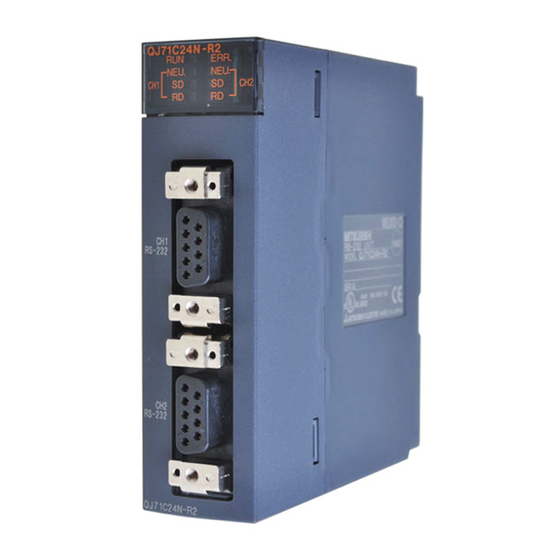
4 SETTINGS AND PROCEDURES PRIOR TO OPERATION 4.3 Part Names and Functions Part names of Q series C24 are shown below. QJ71C24N QJ71C24 ( 1) QJ71C24N ERR. NEU. NEU. RS-232 (FG) (FG) RS-422 /485 1 The external diagrams of the QJ71C24 are the same as QJ71C24N (except for the model name). 2 The external diagrams of the QJ71C24-R2 are the same as QJ71C24N-R2 (except for the model name). -
Page 85: Qj71C24N
4 SETTINGS AND PROCEDURES PRIOR TO OPERATION (1) LED display list QJ71C24N ERR. NEU. NEU. Display contents RUN Normal operation display — Error display ( 1) Neutral status on the CH1 ( 3) side display ( 2) Transmission status display Reception status display Neutral status on the CH2 ( 3) -
Page 86: Run Err
4 SETTINGS AND PROCEDURES PRIOR TO OPERATION 4.4 External Wiring This section explains wiring between the Q series C24 and external device. As the wiring precautions, external wiring which is resistant to the effects of external noise is a prerequisite for reliable system operation and full use of the Q series C24 function. -
Page 87: Connecting The Rs-232 Interface (Full-Duplex Communications)
4 SETTINGS AND PROCEDURES PRIOR TO OPERATION 4.4.1 Connecting the RS-232 interface (full-duplex communications) The following shows the connection precautions and connection examples when using the Q series C24 RS-232 interface for full-duplex communications. (1) Connection precautions (a) For further information about the following items, see the explanation in the (b) The connection cable FG signal and shield are connected as follows. - Page 88 4 SETTINGS AND PROCEDURES PRIOR TO OPERATION (2) Connection examples (a) Connection example with an external device capable of turning on and off the Signal name RD(RXD) SD(TXD) DTR(ER) DSR(DR) RS(RTS) CS(CTS) The CD terminal check setting is set according to the specification of the external device.
-
Page 89: Connecting The Rs-422/485 Interface
4 SETTINGS AND PROCEDURES PRIOR TO OPERATION 4.4.2 Connecting the RS-422/485 interface The following shows the connection precautions and connection examples when using the Q series C24 RS-422/485 interface. (1) Connection precautions (a) When connecting the Q series C24 SG and FG signals to the external (b) Connect the shield of the connection cable to the FG terminal on either of Correspondance of the RS-422/485 terminal block and signal location. - Page 90 4 SETTINGS AND PROCEDURES PRIOR TO OPERATION (c) Terminal resistor must be set (or connected) for the station of both ends on Orange Orange (d) If data cannot be communicated with the external device at all, the polarity of POINT (1) For terminal resistor setting/connection described in this section, when the RS- 232 to RS-422 converters or similar device is used at the external device at both ends of the circuit, a terminal resistor must be set, or connected, at the...
- Page 91 4 SETTINGS AND PROCEDURES PRIOR TO OPERATION (b) External device and Q series C24 with 1:n (multidrop) system configuration External device RS-232 External device RS-422/485 cable (c) External device and Q series C24 with n:1 (multidrop) system configuration External device 1) RS-422/485 cable 4 - 10...
- Page 92 4 SETTINGS AND PROCEDURES PRIOR TO OPERATION (d) External device and Q series C24 with m:n (multidrop) system configuration External device 1) RS-232 External device 1) RS-422/485 cable 4 - 11 1) Connection example 1 External device 2) RS-232 C24 1) C24 2) RS-422/485 cable...
-
Page 93: Settings For Gx Developer
4 SETTINGS AND PROCEDURES PRIOR TO OPERATION 4.5 Settings for GX Developer This chapter explains various settings via GX Developer that allow the Q series C24 to perform data communication with external devices. See Section 3.3.3 of the User's Manual (Application) for how to perform the remote password setting. -
Page 94: Switch Settings For I/O And Intelligent Functional Module
4 SETTINGS AND PROCEDURES PRIOR TO OPERATION 4.5.2 Switch settings for I/O and intelligent functional module [Setting purpose] The switch settings for I/O module and intelligent functional module perform the settings for transmission specifications and communication protocol for communicate with external devices. [Setting procedure] [GX Developer] For screen display, see the GX Developer Operating Manual. - Page 95 4 SETTINGS AND PROCEDURES PRIOR TO OPERATION (a) Transmission setting (CH1 side: switch 1 (lower level); CH2 side: switch 3 4 - 14 (lower level)) CH1 side CH2 side Description Operation setting Data bit Parity bit Even/odd parity Stop bit Sum check code Write during RUN Setting modifications...
- Page 96 4 SETTINGS AND PROCEDURES PRIOR TO OPERATION POINT (1) A setting change in the connected interface side should be set to Allowed, in order to register a user frame to the flash ROM from an external device using the MC protocol. (2) Setting changes in interfaces on the CH1 and CH2 sides should both be set to Allowed, in order to register the system setting values and user frames to the flash ROM from the PLC CPU.
- Page 97 4 SETTINGS AND PROCEDURES PRIOR TO OPERATION (b) Communication rate setting (CH1 side: switch 1 (upper level); CH2 side: Communication rate Bit position (Unit: bps) b15 to b8 1200 2400 4800 9600 (c) Communication protocol setting (CH1 side: switch 2; CH2 side: switch 4) Set number Description GX Developer connection...
- Page 98 4 SETTINGS AND PROCEDURES PRIOR TO OPERATION (d) Station number setting (switch 5 (common for both CH1 and CH2 sides)) POINT If the communication of data with external device is to be started, check the specifications of the functions to be used and then make the settings and connect the cables.
- Page 99 4 SETTINGS AND PROCEDURES PRIOR TO OPERATION (b) Do not use the above settings for the following cases, because linked POINT When two interfaces are in linked operation, the transmission time for one character becomes equal to the hardware gate off time of the Q series C24. (c) The data flow in linked operation is as follows.
- Page 100 4 SETTINGS AND PROCEDURES PRIOR TO OPERATION REMARK The following describes the header information that is added by the Q series C24 to a message in linked operation. 1) When communicating with ASCII code (formats 1 to 4) The following 13/15 character header information is added immediately before the control code (ENQ/STX/ACK/NAK) at the start of each message (13 characters for formats 1, 3 and 4;...
-
Page 101: The Intelligent Function Module Interrupt Pointer Setting
4 SETTINGS AND PROCEDURES PRIOR TO OPERATION 4.5.3 The Intelligent function module interrupt pointer setting The following explains the interrupt pointer setting with GX Developer in order to receive data using an interrupt program. For the method to receive data using an interrupt program, see User's Manual (Applications) Chapter 4. - Page 102 4 SETTINGS AND PROCEDURES PRIOR TO OPERATION (3) Start I/O No. on the intelligent module (unit) side (4) Start SI No. on intelligent module (unit) side 4 - 21 Set the start I/O No. for the Q series C24. 1) Assign control numbers (SI) on the Q series C24 side to the interrupt pointers (Ixx) used in the sequence program.
-
Page 103: Settings With The Utility Package (Gx Configurator-Sc)
4 SETTINGS AND PROCEDURES PRIOR TO OPERATION 4.6 Settings with the Utility Package (GX Configurator-SC) The settings defined with GX Configurator-SC for operation of the Q series C24 are described in Chapter 8. The following concerns the data set from GX Configurator-SC. 1) Data set in the Q series C24 for the use of specific functions 2) Data set in the PLC CPU to communicate information between the Q series C24 and the PLC CPU of the mounting station. - Page 104 4 SETTINGS AND PROCEDURES PRIOR TO OPERATION [Setting items] Setting item Flash ROM access register/read/delete result CH1/CH2 LED ON status, communication error status ( Switch setting error, mode switching error status ( Number of registered user frame Flash ROM system parameters write result Modem function error code Modem function sequence status Number of data registrations for connection...
- Page 105 4 SETTINGS AND PROCEDURES PRIOR TO OPERATION (1) Devices (a) Set the word device of the PLC CPU which stores error and status (b) The devices used must be of the types X, Y, M, L, B, T, C, ST, D, W, R, or (c) The device can be set to auto refresh for required information only.
-
Page 106: Individual Station Test
4 SETTINGS AND PROCEDURES PRIOR TO OPERATION 4.7 Individual Station Test After installing the Q series C24 to the base unit of QCPU, perform an individual station test first to check the switch setting (see Section 4.5.2) and operation of the Q series C24. - Page 107 4 SETTINGS AND PROCEDURES PRIOR TO OPERATION (2) Restart the PLC CPU station or reset the CPU. The test starts automatically in about one second. (3) For the Q series C24, the following tests should be performed once. 1) ROM check 2) RAM check 3) Switch check 4) Linked operation setting check (perform this test with the operation setting in...
- Page 108 4 SETTINGS AND PROCEDURES PRIOR TO OPERATION (Procedure 4) Ending a ROM/RAM/switch test (1) Perform the following procedures after checking normal completion/abnormal completion of the test results. Normal completion Upon error occurrence : When an error occurs in a switch check or linked (2) Perform the ending procedure for ROM/RAM/switch test 1) Follow the procedure in Section 4.7.2 to perform an individual loopback test 2) Perform the following procedure to end the test and start data communication...
-
Page 109: Rda
4 SETTINGS AND PROCEDURES PRIOR TO OPERATION 4.7.2 Individual station loopback test The individual station loopback test checks the operation of the communication function of the Q series C24. Follow the procedure below to perform an individual station loopback test. (Procedure 1) Connecting cable (1) Connect cables to two interfaces as follows. - Page 110 4 SETTINGS AND PROCEDURES PRIOR TO OPERATION (Procedure 4) Checking the results of an individual loopback test (1) This test is performed repeatedly. When the ERR LED is off, the test is being executed normally. (2) The test is completed with an error when the ERR LED is lit. Check the error description on one of the following screens.
-
Page 111: Loopback Test
4 SETTINGS AND PROCEDURES PRIOR TO OPERATION 4.8 Loopback Test A loopback test performs a communication test using the loopback test function of the MC protocol, in order to check the connection between the Q series C24 and an external device, the communication function of each device, and the operation of the communication program of the external device. - Page 112 4 SETTINGS AND PROCEDURES PRIOR TO OPERATION (Procedure 5) Ending the loopback test Perform the following procedure according to the function used, and start data communication. • Set the switch settings with GX Developer according to the procedure specified in Section 4.5.2.
-
Page 113: Maintenance And Inspection
4 SETTINGS AND PROCEDURES PRIOR TO OPERATION 4.9 Maintenance and Inspection This section explains the maintenance and inspection and installing and removing of the Q series C24. 4.9.1 Maintenance and inspection The Q series C24 has no special inspection items other than below. For items other than listed below, perform inspection according to the inspection items listed in the User's Manual of the PLC CPU module in order to always use the system in the optimal condition. -
Page 114: When Mounting/Dismounting The Module
4 SETTINGS AND PROCEDURES PRIOR TO OPERATION 4.9.2 When mounting/dismounting the module Please read 4.1, "Handling Precautions" before mounting or dismounting the module, and make sure to pay attention to safety and handle the module properly during the operation. When replacing the Q series C24 and QCPU, it becomes necessary to register the following data on the Q series C24 again for the module to be replaced. -
Page 115: Data Communication Functions
5 DATA COMMUNICATION USING THE MELSEC COMMUNICATION PROTOCOL 5 DATA COMMUNICATION USING THE MELSEC COMMUNICATION PROTOCOL This chapter explains an overview of the MELSEC communication protocol (hereinafter abbreviated as the MC protocol). See the following manual for a detailed explanation of the data communication functions that are available when using the MC protocol. -
Page 116: Message Format And Control Procedure For Data Communication
5 DATA COMMUNICATION USING THE MELSEC COMMUNICATION PROTOCOL (4) Monitoring the PLC CPU This function monitors the operating status of the PLC CPU and the data in the device memory. The PLC CPU status and the device memory data can be sent to the external device at fixed intervals, when an error occurs in the machine equipment, or when certain conditions are satisfied. -
Page 117: Support Of Multiple Cpu System Or Redundant System
5 DATA COMMUNICATION USING THE MELSEC COMMUNICATION PROTOCOL (2) System settings using the GX Configurator-SC When it is necessary to change the default values registered in the Q series C24, perform the settings as indicated in Chapter 8 and register these to the flash ROM in the Q series C24. -
Page 118: Support For The Qcpu Remote Password Function
5 DATA COMMUNICATION USING THE MELSEC COMMUNICATION PROTOCOL 5.1.5 Support for the QCPU remote password function This section explains an overview of the remote password function when a remote password is set for the Q series C24 mounted to a QCPU. See Chapter 3 of the User's Manual (Application) for a detailed explanation. - Page 119 5 DATA COMMUNICATION USING THE MELSEC COMMUNICATION PROTOCOL REMARK The remote password should be set to a QCPU using GX Developer in order to use the remote password function of QCPU. • Unlocking the remote password is possible only for the QCPU of the local station with the Q series C24.
-
Page 120: Utilizing The Mx Component
5 DATA COMMUNICATION USING THE MELSEC COMMUNICATION PROTOCOL (b) Modem function monitor/test by GX Configurator-SC Monitored items in the “modem function monitor/test” screen Remote password mismatch notification count designation Remote password mismatch notification accumulated count designation Accumulated count of unlock process normal completion Accumulated count of unlock process abnormal completion Accumulated count of lock process based on circuit disconnection 5.2 Utilizing the MX Component... - Page 121 6 DATA COMMUNICATION USING THE NON PROCEDURE PROTOCOL 6 DATA COMMUNICATION USING THE NON PROCEDURE PROTOCOL Data communication using the non procedure protocol is a function for sending and receiving data between a PLC CPU and an external device using the message format and transmission control procedure specified by the user.
-
Page 122: Data Reception From The External Device
6 DATA COMMUNICATION USING THE NON PROCEDURE PROTOCOL 6.1 Data Reception from the External Device This section explains data reception from the external device. There are two methods for receiving data: the "reception via receive complete code" for receiving variable length messages, and the "reception via received data count" for receiving fixed length messages. - Page 123 6 DATA COMMUNICATION USING THE NON PROCEDURE PROTOCOL (1) Data reception by receive complete code (for variable length reception) (a) This method is used to send data by adding the receive complete code set in (b) When the Q series C24 receives the receive complete code data preset in (c) The receive complete code can be changed to match the specifications of the (d) The Q series C24 issues a receive data read request to the PLC CPU as 6 - 3...
- Page 124 6 DATA COMMUNICATION USING THE NON PROCEDURE PROTOCOL External device Q series C24 Reception data request signal (X3/XA) 6 - 4 • If the next data (LF, etc.) is not received within the time set in the non reception monitoring time (timer 0) after CR is received, the Q series C24 stores the received data up to CR to the buffer memory receive data storage area and turns on the following signals to the PLC CPU.
- Page 125 6 DATA COMMUNICATION USING THE NON PROCEDURE PROTOCOL (2) Reception by received data count (For fixed length reception) (a) This method is used to receive messages of the same length (size) from the (b) When the Q series C24 receives data of the received data count preset in (c) The received data count default value is set to 511 (words).
-
Page 126: The Receive Area And The Received Data List
6 DATA COMMUNICATION USING THE NON PROCEDURE PROTOCOL 6.1.2 The receive area and the received data list The following shows the list of the receive area and the receive data for performing data reception using the non procedure protocol. (1) Receive area The receive area is a memory area for storing the data received from the external device and the receive data count in order to read the receive data for the PLC CPU. - Page 127 6 DATA COMMUNICATION USING THE NON PROCEDURE PROTOCOL POINT (1) The position and size of the receive area in the buffer memory can be changed with the GX Configurator-SC in accordance with the specifications of the external device and the receive data length. (See Section 8.4.7.) (a) When changing the position and size of the receive area in the buffer (b) If the following functions are also used when the position and size of the (2) When sending data from the external device to the Q series C24, one of the...
- Page 128 6 DATA COMMUNICATION USING THE NON PROCEDURE PROTOCOL (2) Receive data list The following describes the data list when data received from an external device is stored to the receive area. 1) The receive message is stored to the Q series C24 buffer memory (receive 2) The data is stored to the receive data storage area in low address (L) Head OS area...
- Page 129 6 DATA COMMUNICATION USING THE NON PROCEDURE PROTOCOL REMARK (1) Data reception when the receive data storage area is larger than External device Q series C24 Reception data read request signal Sequence program (2) Data reception when the receive data storage area is smaller External device Q series C24 Reception data read request...
- Page 130 6 DATA COMMUNICATION USING THE NON PROCEDURE PROTOCOL 1st data 511 words External device Q series C24 Reception data read request signal Sequence program 6 - 10 2) Reception by received data count When the received data count is set larger than the receive data storage area, the receive buffer memory length (default: 512 words) -1 set in buffer memory addresses A7 /147...
-
Page 131: Sequence Program For Data Reception
6 DATA COMMUNICATION USING THE NON PROCEDURE PROTOCOL 6.1.3 Sequence program for data reception This section explains the sequence program for data reception. For details on the INPUT instruction for data reception, see Chapter 9. X3 Read request Abnormal detection Q series C24 ready signal (X1E) Reception data read request... -
Page 132: Program Example
6 DATA COMMUNICATION USING THE NON PROCEDURE PROTOCOL 4) The device completing the INPUT instruction turns ON when the reading of receive data is completed. When the complete device + 1 (abnormal completion signal) turns ON, the error code is stored in the control data completion status (S1 + 1). (Program example) When the Q series C24 I/O signals are from X/Y00 to X/Y1F: For normal completion... - Page 133 6 DATA COMMUNICATION USING THE NON PROCEDURE PROTOCOL POINT (1) Receive data can also be read using interrupt programs. For more details on reading receive data with interrupt programs, see Chapter 4 of the User's Manual (Application). Note that if the reading of data received from the same interface is to be performed, it is not possible to combine the reading of data received by the main program and reading of data received by the interrupt program.
-
Page 134: Receive Data Clear
6 DATA COMMUNICATION USING THE NON PROCEDURE PROTOCOL 6.1.4 Receive data clear For the data reception by a non procedure protocol, if the transmission of data from a transmitting device is interrupted due to trouble occurring, it may be necessary for the data received up to the present time are cleared in the receiving device and for the data to be received again from the start. - Page 135 6 DATA COMMUNICATION USING THE NON PROCEDURE PROTOCOL (3) Receive data clear procedure using FROM/TO instruction Write and read the buffer memory receive data clear request area (addresses A8 /148 When resuming data communications with an external device, resume it after completing the reception data clear processing with the Q Series C24.
- Page 136 6 DATA COMMUNICATION USING THE NON PROCEDURE PROTOCOL Q series C24 Buffer memory address A8 PLC CPU (Program) 1 Add the dotted line portion to the sequence program when the function version A Q Series C24 is used. (Carry out communications when M19 is ON.) 6 - 16 Send request execution disabled...
-
Page 137: How To Detect Reception Errors
6 DATA COMMUNICATION USING THE NON PROCEDURE PROTOCOL 6.1.5 How to detect reception errors This section explains how to detect errors that may occur when receiving data from the external device. The following items are considered as the primary causes of errors that may occur during data reception. - Page 138 6 DATA COMMUNICATION USING THE NON PROCEDURE PROTOCOL (2) Confirmation using the module and GX Configurator-SC 1) Confirmation using the display LED 2) Confirmation using GX Configurator-SC 3) Confirming the error code (3) Receive data when a reception error occurs (a) Storing receive data (b) Reading receive data 6 - 18...
- Page 139 6 DATA COMMUNICATION USING THE NON PROCEDURE PROTOCOL PLC CPU Q25HCPU Reception MODE. Receive data abnormal RUN. ERR. count storage detection USER. area BAT. BOOT. Receive data storage area INPUT instruction RS-232 Q series C24 ready signal (X1E) Reception data read request (X3) Reception abnormal (X4)
-
Page 140: Received Data Count And Receive Complete Code Settings
6 DATA COMMUNICATION USING THE NON PROCEDURE PROTOCOL 6.1.6 Received data count and receive complete code settings The following default values have been set for the received data count and receive complete code that are used for data reception with the non procedure protocol. If it is necessary to change the following default settings, change the settings on the GX Configurator-SC "Non procedure system setting"... - Page 141 6 DATA COMMUNICATION USING THE NON PROCEDURE PROTOCOL (2) Setting values that can be changed Of the initial settings from GX Configurator-SC stored in the buffer memory, only the following setting values can be changed after data communication has started. •...
-
Page 142: Sending Data To The External Device
6 DATA COMMUNICATION USING THE NON PROCEDURE PROTOCOL 6.2 Sending Data to the External Device This section explains data transmission from the PLC CPU to the external device. 6.2.1 Transmission methods The following shows how to send data in any format using the non procedure protocol. PLC CPU Transmission data ) (41... -
Page 143: Arrangement And Contents Of The Transmission Area And The Transmission Data
6 DATA COMMUNICATION USING THE NON PROCEDURE PROTOCOL 6.2.2 Arrangement and contents of the transmission area and the transmission data This section explains the arrangement and contents of the transmission area and the transmission data for performing data transmission using the non procedure protocol. (1) Transmission area The transmission area is a memory area for storing the data and the data count that are transmitted from the PLC CPU to the external device via the Q series... - Page 144 6 DATA COMMUNICATION USING THE NON PROCEDURE PROTOCOL POINT (1) The position and size of the transmission area in the buffer memory can be changed with GX Configurator-SC in accordance with the specifications of the external device and the received data length. (See Sections 8.4.5 and 8.4.7.) (a) When changing the position and size of the transmission area in the buffer (b) If the following functions are also used when the position and size of the (2) Set the size of data per data transmission from the PLC CPU to the external...
-
Page 145: Sequence Program For Transmission Data
6 DATA COMMUNICATION USING THE NON PROCEDURE PROTOCOL (2) Transmission data arrangement The following example shows an arrangement of the transmission data to be sent to the external device when storing it in the transmission area. (Example) When transmitting "ABCDEFG123" (The transmit area is the default CH1 side address Buffer memory... - Page 146 6 DATA COMMUNICATION USING THE NON PROCEDURE PROTOCOL Q series C24 ready signal (X1E) Transmission instruction OUTPUT instruction OUTPUT instruction complete device OUTPUT instruction complete device + 1 (normal completion/abnormal completion) Transmission data count designation area (buffer memory address: 400 Transmission data storage area (buffer memory address: 401 1) Starts the local station PLC.
- Page 147 6 DATA COMMUNICATION USING THE NON PROCEDURE PROTOCOL (Program example) When Q series C24 I/O signals are from X/Y00 to X/Y1F: For normal completion Interface number (0001 Transmission result (0000 Transmission data count (0005 (4241 Transmission data (0A0D For abnormal completion Interface number (0001 Transmission result...
-
Page 148: How To Detect Transmission Errors
6 DATA COMMUNICATION USING THE NON PROCEDURE PROTOCOL 6.2.4 How to detect transmission errors This section explains how to detect errors that may occur when sending data to the external device. The following items are considered as the primary causes of errors that may occur during data transmission. - Page 149 6 DATA COMMUNICATION USING THE NON PROCEDURE PROTOCOL (2) Confirmation using the module and GX Configurator-SC 1) Confirmation using the display LED 2) Confirmation using the GX Configurator-SC 3) Confirming the error code POINT When a transmission error occurs, the PLC CPU may not transmit all the designated data.
-
Page 150: Data Communications Precautions
6 DATA COMMUNICATION USING THE NON PROCEDURE PROTOCOL 6.3 Data Communications Precautions The following describes the precautions to be taken during non procedure protocol data communications. (1) The Q series C24 transmission sequence initialization conditions The initial status indicates the status where transmission has stopped and reception data has been discarded. - Page 151 6 DATA COMMUNICATION USING THE NON PROCEDURE PROTOCOL MELSEC-Q (4) Retry processing for data reception errors The data when reception error occurred is discarded and only the data for the normal reception is taken into the Q series C24. For this reason, the reception message may be missing data when an error occurs.
- Page 152 7 DATA COMMUNICATION USING THE BIDIRECTIONAL PROTOCOL 7 DATA COMMUNICATION USING THE BIDIRECTIONAL PROTOCOL Data communication using the bidirectional protocol is a function for sending/receiving any data using the message format and transmission control procedure for the Q series C24 bidirectional protocol between external devices and PLC CPUs. Any external devices that can install application programs and transmit and receive data in accordance with the MELSEC PLC protocol can communicate with the PLC CPUs using the bidirectional protocol.
-
Page 153: Receiving Methods
7 DATA COMMUNICATION USING THE BIDIRECTIONAL PROTOCOL 7.1 Data Reception from the External Device This section explains the data reception from the external device. 7.1.1 Receiving methods The following shows how to receive data sent from the external device using the bidirectional protocol. - Page 154 7 DATA COMMUNICATIONS USING BIDIRECTIONAL PROTOCOL 1) When the control code ENQ is received, the Q series C24 starts data reception processing. When the data specified by the data length is received, the Q series C24 ends the reception processing of that data. If "Sum check"...
-
Page 155: Arrangement And Contents Of The Receive Area And The Receive Data
7 DATA COMMUNICATIONS USING BIDIRECTIONAL PROTOCOL 7.1.2 Arrangement and contents of the receive area and the receive data This section shows the arrangement and contents of the receive area and the receive data for performing data reception using the bidirectional protocol. (1) Receive area The receive area is a memory that stores the received data length (receive data count) and data area received from an external device. - Page 156 7 DATA COMMUNICATIONS USING BIDIRECTIONAL PROTOCOL POINT (1) The position and size of the receive area in the buffer memory can be changed with GX Configurator-SC in accordance with the specifications of the external device and the received data length. (See Sections 8.4.5 and 8.4.7.) (a) When changing the position and size of the receive area in the buffer (b) If the following functions are also used when the position and size of the (2) When sending data to the Q series C24 from the external device, one of the...
- Page 157 7 DATA COMMUNICATIONS USING BIDIRECTIONAL PROTOCOL (2) Arrangement of receive data The following example illustrates the arrangement of data received from the external device when it is stored in the receive area. 1) The receive message is stored to the Q series C24 buffer memory (receive 2) The data is stored to the receive data storage area in low address (L) Q series C24 Receive area...
- Page 158 7 DATA COMMUNICATIONS USING BIDIRECTIONAL PROTOCOL (b) Data length (c) Data portion 7 - 7 This indicates the number of bytes or words for the data portion of the message. The unit of data length (words/bytes) is in accordance with the word/byte units designation in GX Configurator-SC.
- Page 159 7 DATA COMMUNICATIONS USING BIDIRECTIONAL PROTOCOL (d) Sum check code (Example) The following shows the sum check code when "ABCDEFGHIJ " and the numeric value 100 are sent as data (when the unit is in bytes). External device side Q series C24 Contents of 0327 memory 7 - 8...
- Page 160 7 DATA COMMUNICATIONS USING BIDIRECTIONAL PROTOCOL (e) Error code 7 - 9 The error code indicates the definition of the error during NAK response. (For more details on the error codes, see Chapter 10.) 1) For data communication from the external device to the Q series C24 For error codes from the external device, transmit the codes specified by the user.
-
Page 161: Sequence Program For Data Reception
7 DATA COMMUNICATIONS USING BIDIRECTIONAL PROTOCOL 7.1.3 Sequence program for data reception This section explains the sequence program for data reception. For details on the BIDIN instruction for data reception, see Chapter 9. X3 Read request Q series C24 ready signal (X1E) Reception data read (X3) - Page 162 7 DATA COMMUNICATIONS USING BIDIRECTIONAL PROTOCOL (Program example) When Q series C24 I/O signals are from X/Y00 to X/Y1F: For normal completion Interface number Reception result Receive data count Allowable receive data count Receive data Receive data 7 - 11 Address (10) When the received data count is larger than the...
- Page 163 7 DATA COMMUNICATIONS USING BIDIRECTIONAL PROTOCOL POINT (1) Receive data can also be read using interrupt programs. For more details on reading receive data with interrupt programs, see Chapter 4 of the User's Manual (Application). Note that if the reading of data received from the same interface is to be performed, it is not possible to combine the reading of data received by the main program and reading of data received by the interrupt program.
-
Page 164: How To Detect Reception Errors
7 DATA COMMUNICATIONS USING BIDIRECTIONAL PROTOCOL 7.1.4 How to detect reception errors This section explains how to detect errors that may occur when receiving data from the external device. The following items are considered as the primary causes of errors that may occur during data reception. -
Page 165: Receive Data Clear
7 DATA COMMUNICATIONS USING BIDIRECTIONAL PROTOCOL (2) Confirmation using the module and GX Configurator-SC 1) Confirmation using the display LED 2) Confirmation using GX Configurator-SC 3) Confirming the error code (3) Handling of receive data when a reception error occurs 1) All of the receive data for which an error was detected is ignored and an 2) The receive area in the buffer memory will contain the data received normally 7.1.5 Receive data clear... -
Page 166: Transmission Methods
7 DATA COMMUNICATIONS USING BIDIRECTIONAL PROTOCOL 7.2 Sending Data to the External Device This section explains data transmission from the PLC CPU to the external device. 7.2.1 Transmission methods The following shows the method of sending data to the external device through data communication using the bidirectional protocol. -
Page 167: Arrangement And Contents Of The Transmission Area And The Transmission Data
7 DATA COMMUNICATIONS USING BIDIRECTIONAL PROTOCOL 7.2.2 Arrangement and contents of the transmission area and the transmission data This section explains the arrangement and contents of the transmission area and the transmission data for performing data transmission using the bidirectional protocol. For details on the contents of transmission data, see Section 7.1.2 (3). - Page 168 7 DATA COMMUNICATIONS USING BIDIRECTIONAL PROTOCOL POINT (1) The position and size of the transmission area in the buffer memory can be changed with GX Configurator-SC in accordance with the specifications of the external device and the transmission data length. (See Section 8.4.5.) (a) When changing the position and size of the transmission area in the buffer (b) If the following functions are also used when the position and size of the (2) Set the size of data per data transmission from the PLC CPU to the external...
- Page 169 7 DATA COMMUNICATIONS USING BIDIRECTIONAL PROTOCOL (2) Transmission data arrangement The following example shows an arrangement of the transmission data to be sent to the external device when storing it in the transmission area. (Example) When "ABCDEFG123" is sent: Q series C24 Transmission area (buffer memory) Transmission...
-
Page 170: Sequence Program For Data Transmission
7 DATA COMMUNICATIONS USING BIDIRECTIONAL PROTOCOL 7.2.3 Sequence program for data transmission A sequence program for data transmission is explained below. For details on the BIDOUT instruction for data transmission, see Chapter 9. Transmission instruction Q series C24 ready signal (X1E) Transmission instruction BIDOUT instruction... - Page 171 7 DATA COMMUNICATIONS USING BIDIRECTIONAL PROTOCOL 1) Starts the local station PLC. The setting values for GX Developer are stored in the Q series C24. 2) Inputs the user data transmission instruction signal. 3) Executes the BIDOUT instruction after storing the transmission data and the control data for the BIDOUT instruction in the device.
- Page 172 7 DATA COMMUNICATIONS USING BIDIRECTIONAL PROTOCOL For normal completion Interface number (0001 Transmission result (0000 Transmission data count (0005 (4241 Transmission data (0A0D For abnormal completion Interface number (0001 Transmission result (other than 0000 Transmission data count (0005 (4241 Transmission data (0A0D POINT (1) The SPBUSY instruction is used to read the execution status when using a...
-
Page 173: How To Detect Transmission Errors
7 DATA COMMUNICATIONS USING BIDIRECTIONAL PROTOCOL 7.2.4 How to detect transmission errors This section explains how to detect errors that may occur when sending data to the external device. The following items are considered as the primary causes of errors that may occur during data transmission. - Page 174 7 DATA COMMUNICATIONS USING BIDIRECTIONAL PROTOCOL (2) Confirmation using the module and GX Configurator-SC 1) Confirmation using the display LED 2) Confirmation using GX Configurator-SC 3) Confirming the error code 7 - 23 When the Q series C24 detects an error, including a reception error, the ERR LED lights up.
-
Page 175: Processing When Simultaneous Transmission Performed During Full-Duplex Communications
7 DATA COMMUNICATIONS USING BIDIRECTIONAL PROTOCOL 7.3 Processing when Simultaneous Transmission Performed During Full-Duplex Communications This section explains the processing when simultaneous transmissions occur in full- duplex communication. 7.3.1 Processing when simultaneous transmissions occur This section explains the processing performed by the Q series C24 when the external device and the Q series C24 transmit at the same time during data communications using the bidirectional protocol. -
Page 176: Communication Data Processing When Simultaneous Transmissions Occur
7 DATA COMMUNICATIONS USING BIDIRECTIONAL PROTOCOL 7.3.2 Communication data processing when simultaneous transmissions occur Examples of the Q series C24 communication data processing for various settings of "Simultaneous transmission data valid/invalid designation" by GX Configurator-SC are explained. (1) Transmission: valid, reception: valid External device Q series C24 1)-1... - Page 177 7 DATA COMMUNICATIONS USING BIDIRECTIONAL PROTOCOL (4) Transmission: invalid, reception: invalid External device Q series C24 Arbitrary data 1)-1 REMARK Time-check timer 1 (response monitoring time) shown in the illustration is described in Section 6.2 of User's Manual (Application). POINT When the transmission control (see Chapter 9 of User's Manual (Application)) is performed, and the simultaneous transmission data valid/invalid designation sets that the receive data is valid and transmission data is valid, the Q series C24...
-
Page 178: Data Communications Precautions
7 DATA COMMUNICATIONS USING BIDIRECTIONAL PROTOCOL 7.4 Data Communications Precautions The following shows the precautions when performing data communications using the bidirectional protocol. (1) When the transmission sequence is in the initial status, it indicates that data transmission and reception processing has not been started. The Q series C24 transmission sequence is initialized in the following cases. - Page 179 7 DATA COMMUNICATIONS USING BIDIRECTIONAL PROTOCOL POINT (1) Perform error processing according to the error code received immediately after the NAK message at the device that received NAK as the response message after data transmission. Chapter 10 shows the error codes that are transmitted from the Q series C24. (2) If the Q series C24 receives an NAK response while transmitting data to an external device, it completes data transmission, then reads the NAK, perform abnormal completion.
- Page 180 8 UTILITY PACKAGE (GX Configurator-SC) 8 UTILITY PACKAGE (GX Configurator-SC) The GX Configurator-SC is a tool that supports the production of necessary PLC programs with initial setting, monitoring and testing, and data communication processing of the Q series C24. The GX Configurator-SC is composed of an intelligent function utility and protocol FB support function.
-
Page 181: Functions Available With Utility Package
8 UTILITY PACKAGE (GX Configurator-SC) 8.1 Functions Available with Utility Package The following table lists the utility package function. Function Refresh the Q series C24's error codes and set devices on the PLC Auto refresh setting CPU side. User frame Register the user frame in the flash ROM. -
Page 182: Installing And Uninstalling Utility Package
8 UTILITY PACKAGE (GX Configurator-SC) 8.2 Installing and Uninstalling Utility Package See "Method of installing the MELSOFT Series" attached with the utility package regarding the install and uninstall operation for the utility package. 8.2.1 Usage precautions The following describes the precautions on using the utility package: (1) Important safety information Since the utility package is add-in software for GX Developer, read "Safety Precautions"... -
Page 183: Qj71C24N-R2
8 UTILITY PACKAGE (GX Configurator-SC) (6) About the number of parameters that can be set in GX Configurator-SC The number of parameters that can be set by the GX Configurator for an intelligent function module installed in the CPU module and in a remote I/O station of the MELSECNET/H network system is limited. -
Page 184: Operating Environment
8 UTILITY PACKAGE (GX Configurator-SC) 8.2.2 Operating environment The operating environment of the personal computer where the GX Configurator-SC is used is explained. Item Installation (Add-in) destination Computer main unit Required memory For installation Hard disk free space For operation Display Operating system 1: Install the GX Configurator-SC in GX Developer Version 4 or higher in the same language. -
Page 185: Explanation Of Utility Package Operation
8 UTILITY PACKAGE (GX Configurator-SC) 8.3 Explanation of Utility Package Operation 8.3.1 Operation overview GX Developer screen [Tools] – [Intelligent function utility] – [Start] Intelligent Function Module Select Parameter Setting Module screen See Section 8.3.2 When used via offline operation Select [Tools] –... - Page 186 8 UTILITY PACKAGE (GX Configurator-SC) 1) When using online operation Select [Online] – [Monitor/test] from the menu bar. Select monitor/test module screen Monitor/test Select the parameter setting module for monitor/test. Monitor/test screen See Section 8.4 See Section 8.6 POINT (1) When the setting operation is complete in each system setting screen, register the system setting data in the flash ROM, then restart the PLC CPU resume data transmission.
- Page 187 8 UTILITY PACKAGE (GX Configurator-SC) REMARK The following diagram illustrates the overview of a procedure in which the GX Configurator-SC is used to change the system setting values of the Q series C24 and save the new values to a file or write them to the Q series C24's flash ROM. Start Do you wish to change the setting values via...
- Page 188 8 UTILITY PACKAGE (GX Configurator-SC) 1) (Online operation) Start the [Monitor/test] screen. Is the original data saved? Set the flash ROM write allow/prohibit designation to "allowed". Display the system setting sub-screens for changing the setting values. Click each of the setting items corresponding to the setting values to be changed.
- Page 189 8 UTILITY PACKAGE (GX Configurator-SC) 8.3.2 Starting the intelligent function module utility (displaying the [select parameter setting module] screen) [Purpose] Start the intelligent function module utility from the GX Developer, and display the module selection screen for the intelligent function module utility parameter setting. The screens that perform system setting, auto refresh setting, and monitoring/testing for the Q series C24 can be started from this module selection screen.
- Page 190 8 UTILITY PACKAGE (GX Configurator-SC) (2) Command buttons (3) Menu bar (a) File items (b) Online items (c) Tool items (d) Help items 8 - 11 Initial settings : Cannot be selected. Auto refresh : Starts the auto refresh setting screen. Delete : Deletes the initial settings and auto refresh settings.
- Page 191 8 UTILITY PACKAGE (GX Configurator-SC) POINT (1) Saving the intelligent function module parameter files Since files cannot be saved using the GX Developer project save operation, save the files on the module selection screen for parameter setting described above. (2) Reading from and writing to PLC operations for the intelligent function module parameters using GX Developer (a) After the intelligent function module parameters are saved in a file, they (b) Set the target PLC using the GX Developer [Online]...
-
Page 192: Performing Common Utility Operations
8 UTILITY PACKAGE (GX Configurator-SC) 8.3.3 Performing common utility operations This section explains how to perform the common operations in the data setting, auto refresh setting and monitor/test screens. (1) Available Control Keys The following table lists the special keys that can be used during operation of utility and their applications: Name of key Ctrl... - Page 193 8 UTILITY PACKAGE (GX Configurator-SC) POINT (1) When the setting operation is complete in each system setting screen, register the system setting data in the flash ROM, then restart the PLC CPU to resume data transmission. (2) If two or more intelligent function module utility package are running, perform each operation after selecting the target utility package from the task bar and making it active.
-
Page 194: Ch1
8 UTILITY PACKAGE (GX Configurator-SC) <Flash ROM data> (a) The data set in [Flash ROM setting] can be saved in the desired directory (b) Operations 4) and 5) shown in Figure 8.1 are performed as follows: GX Developer/ GX Configurator-SC Project QCPU Q25HCPU... -
Page 195: System Registration To Flash Rom
8 UTILITY PACKAGE (GX Configurator-SC) 8.4 System Registration to Flash ROM [Purpose] Display the menu screen for flash ROM registration, which is used to change the initial values set in the Q series C24's buffer memory. [Startup procedure] • Online operation •... - Page 196 8 UTILITY PACKAGE (GX Configurator-SC) [Setting Items] The following table shows the selection menus for system setting/registration to be displayed: Function User frame registration Data for modem initialization registration Data for modem connection registration Modem function system setting Transmission control and others system setting MC protocol system setting Non procedure system setting Bidirectional system setting...
-
Page 197: User Frame Registration
8 UTILITY PACKAGE (GX Configurator-SC) 8.4.1 User frame registration [Purpose] Register the user frame used in the following functions: • On-demand function using the MC protocol. • Data transmission/receive function using the non procedure protocol. [Startup procedure] • Online operation •... -
Page 198: Data For Modem Initialization Registration
8 UTILITY PACKAGE (GX Configurator-SC) 8.4.2 Data for modem initialization registration [Purpose] Register the data for initializing the modem connected to the Q series C24. [Startup procedure] • Online operation • Offline operation [Setting screen] [Setting item] Setting item Data for user initialization 1 to 30 User control data Data for user initialization 1 to 30 Initialization command... -
Page 199: Data For Modem Connection Registration
8 UTILITY PACKAGE (GX Configurator-SC) 8.4.3 Data for modem connection registration [Purpose] For data communication and notification using the modem function, register the data for connection with external devices. [Startup procedure] • Online operation • Offline operation [Setting screen] [Setting items] Setting item Pager receiver designation Telephone number... -
Page 200: Modem Function System Setting/Registration
8 UTILITY PACKAGE (GX Configurator-SC) 8.4.4 Modem function system setting/registration [Purpose] For data communication using the modem function, register system setting values. [Startup procedure] • Online operation • Offline operation [Setting screen] [Setting items] Setting item Modem connection channel designation Notification execution designation Number of connection retries designation Connection retry interval designation... -
Page 201: Transmission Control And Others System Setting
8 UTILITY PACKAGE (GX Configurator-SC) 8.4.5 Transmission control and others system setting [Purpose] For data communication with external devices, register system setting values for the transmission control method, monitoring time, and buffer memory assignment. [Startup procedure] • Online operation • Offline operation [Setting screen] 8 - 22 [Monitor] screen... - Page 202 8 UTILITY PACKAGE (GX Configurator-SC) [Setting items] Setting item DTR/DSR (ER/DR), DC control designation DC1/DC3 (Xon/Xoff) code designation DC2/DC4 code designation Communication system designation CD terminal check designation Half-duplex communications control designation Simultaneous transmission priority/non-priority designation Half-duplex communications control designation Retransmission time transmission method designation No-reception monitoring time (timer 0) designation Response monitoring time (timer 1) designation...
-
Page 203: Mc Protocol System Setting
8 UTILITY PACKAGE (GX Configurator-SC) 8.4.6 MC protocol system setting [Purpose] For data transmission using the MC protocol, register system setting values. [Startup procedure] • Online operation • Offline operation [Setting screen] [Setting items] Setting item On-demand Buffer memory head address designation function designation Data length designation... -
Page 204: Non Procedure System Setting
8 UTILITY PACKAGE (GX Configurator-SC) 8.4.7 Non procedure system setting [Purpose] For data transmission using the non procedure protocol, register system setting values. [Startup procedure] • Online operation • Offline operation [Setting screen] [Setting items] Setting item Received data count designation Receive complete code designation User frame use enable/disable designation Receive user... -
Page 205: Bidirectional System Setting
8 UTILITY PACKAGE (GX Configurator-SC) 8.4.8 Bidirectional system setting [Purpose] For data transmission using the bidirectional protocol, register system setting values. [Startup procedure] • Online operation • Offline operation [Setting screen] [Setting item] Setting item Simultaneously transmission data valid/invalid designation 8 - 26 [Monitor] screen Bidirectional system setting... -
Page 206: Plc Cpu Monitoring System Setting
8 UTILITY PACKAGE (GX Configurator-SC) 8.4.9 PLC CPU monitoring system setting [Purpose] Register system setting values to use the PLC CPU monitoring function. [Startup procedure] • Online operation • Offline operation [Setting screen] 8 - 27 [Monitor] screen Monitoring system setting [Flash ROM setting] screen MELSEC-Q Monitoring system setting... - Page 207 8 UTILITY PACKAGE (GX Configurator-SC) [Setting items] Setting item Cycle time units designation Cycle time designation PLC CPU monitoring function designation PLC CPU monitoring transmission measure designation Transmission pointer Constant cycle Output count designation transmission Data No. for connection designation Number of registered word blocks designation Number of registered bit blocks designation PLC CPU abnormal monitoring designation...
-
Page 208: Transmission User Frame No. Designation System Setting
8 UTILITY PACKAGE (GX Configurator-SC) 8.4.10 Transmission user frame No. designation system setting [Purpose] Register the output frame number to transmit data with the non procedure protocol using the user frame. [Startup procedure] • Online operation • Offline operation [Setting screen] [Setting item] Setting item Output frame No. -
Page 209: Resetting The Buffer Memory/Flash Rom Setting Values To The Default Values
8 UTILITY PACKAGE (GX Configurator-SC) 8.4.11 Resetting the buffer memory/flash ROM setting values to the default values This section explains how to reset the values set in the buffer memory/flash ROM to their default values. [Startup procedure] [Online] [Monitor] screen [Operating procedure] (Procedure 1) In the [Monitor] screen, select [Default request] for [System setting default]. -
Page 210: Auto Refresh Setting
8 UTILITY PACKAGE (GX Configurator-SC) MELSEC-Q 8.5 Auto Refresh Setting The Auto Refresh Settings are used to automatically store the error information and status information currently stored in the Q series C24's buffer memory in the device specified by the PLC CPU. For details, see Section 4.6. -
Page 211: Monitor/Test
8 UTILITY PACKAGE (GX Configurator-SC) 8.6 Monitor/Test [Purpose] The displayed menu screen is used to perform various operations, including the monitoring of the Q series C24's operating status and setting values and the testing of its output signals. The monitor/test operations can be performed only via online operation. -
Page 212: X · Y Monitor/Test
8 UTILITY PACKAGE (GX Configurator-SC) 8.6.1 X · Y monitor/test [Purpose] Perform the monitoring of I/O signals and testing of output signals. [Startup procedure] [Monitor] screen [Monitor/test screen] [Monitor/test items] Monitor/test items X00: CH1 Transmission normal completion X01: CH1 Transmission abnormal completion X02: CH1 Transmission processing in progress X03: CH1 Reception data read request X04: CH1 Reception abnormal detection... -
Page 213: Modem Function Monitor/Test
8 UTILITY PACKAGE (GX Configurator-SC) 8.6.2 Modem function monitor/test [Purpose for monitor/test] Monitor/test the operating status and setting values of the modem function. [Startup procedure] [Monitor] screen [Monitor/test screen] [Monitor/test items] Monitor/test items Modem function error code Modem function sequence status Number of data registration for connection Number of data registrations for initialization Number of notification execution... - Page 214 8 UTILITY PACKAGE (GX Configurator-SC) Monitor/test items Y11: Connection request Y12: Modem disconnection request Y14: Notification-issued request Modem connection channel designation Notification execution designation Number of connection retires designation Connection retry interval designation Initialization/connection timeout designation Number of initialization retries designation Data No.
-
Page 215: Operation Procedure
8 UTILITY PACKAGE (GX Configurator-SC) [Test Items] The following accumulated count of times counter values can be cleared to "0" by the select test function. Test items Accumulated count of unlock process normal completion Accumulated count of unlock process abnormal completion Accumulated count of lock process based on circuit disconnection Callback permit accumulated count Callback denial accumulated count... -
Page 216: Transmission Control And Others Monitor/Test
8 UTILITY PACKAGE (GX Configurator-SC) 8.6.3 Transmission control and others monitor/test [Purpose] Monitor the RS-232 signal status and the various setting values for data communication. [Startup procedure] [Monitor] screen [Monitor/test screen] [Monitor/test items] Monitor/test items RTS (RS) DSR (DR) DTR (ER) RS-232 control signal status CS (CTS) - Page 217 8 UTILITY PACKAGE (GX Configurator-SC) Monitor/test items Transmission Transmission speed status DTR/DSR (ER/DR), DC control designation DC1/DC3 (Xon/Xoff) code designation DC2/DC4 code designation Communication system designation CD terminal check designation Half-duplex communications control designation Simultaneous transmission priority/non-priority designation Half-duplex communications control designation Retransmission time transmission method designation No-reception monitoring time (timer 0) designation Response monitoring time (timer 1) designation...
-
Page 218: Mc Protocol Monitor
8 UTILITY PACKAGE (GX Configurator-SC) 8.6.4 MC protocol monitor [Purpose] Monitor the status and setting values of the data communication using the MC protocol. [Startup procedure] [Monitor] screen [Monitor screen] 8 - 39 MC protocol monitor MELSEC-Q 8 - 39... - Page 219 8 UTILITY PACKAGE (GX Configurator-SC) [Monitor items] Monitor items Transmission sequence status On-demand execution result Data transmission result Data reception result MC protocol transmission error code X00: CH1 Transmission normal completion X01: CH1 Transmission abnormal completion X02: CH1 Transmission processing in progress X1A: CH1 Global signal Y00: CH1 Transmission request On-demand...
-
Page 220: Non Procedure Monitor/Test
8 UTILITY PACKAGE (GX Configurator-SC) 8.6.5 Non procedure monitor/test [Purpose] Monitor the status and setting values of the data transmission using the non procedure protocol. The test operation for the receive data clear is explained in Section 8.7. [Startup procedure] [Monitor] screen [Monitor/test screen] 8 - 41... - Page 221 8 UTILITY PACKAGE (GX Configurator-SC) [Monitor/test items] Monitor/test items Data transmission result Data reception result Receive user frame nth User frame being transmitted X00: CH1 Transmission normal completion X01: CH1 Transmission abnormal completion X02: CH1 Transmission processing in progress X03: CH1 Reception data read request X04: CH1 Reception abnormal detection Y00: CH1 Transmission request Y01: CH1 Reception data read completion...
-
Page 222: Bidirectional Monitor
8 UTILITY PACKAGE (GX Configurator-SC) 8.6.6 Bidirectional monitor [Purpose] Monitor the status and setting values of the data transmission using the bidirectional protocol. [Startup procedure] [Monitor] screen [Monitor screen] [Monitor items] Monitor items Data transmission result Data reception result X00: CH1 Transmission normal completion X01: CH1 Transmission abnormal completion X02: CH1 Transmission processing in progress X03: CH1 Reception data read request... -
Page 223: Plc Cpu Monitoring Monitor
8 UTILITY PACKAGE (GX Configurator-SC) 8.6.7 PLC CPU monitoring monitor [Purpose] Monitor the operating status and setting values of the PLC CPU monitoring function. [Startup procedure] [Monitor] screen [Monitor screen] 8 - 44 Monitoring monitor MELSEC-Q 8 - 44... - Page 224 8 UTILITY PACKAGE (GX Configurator-SC) [Monitor items] Monitor items Operation status PLC CPU monitoring Execution result function Number of transmission Monitoring condition arrival block No. Cycle time units designation Cycle time designation PLC CPU monitoring function designation PLC CPU monitoring transmission measure designation Transmission pointer Constant cycle Output count designation...
-
Page 225: Transmission User Frame No. Designation Monitor
8 UTILITY PACKAGE (GX Configurator-SC) 8.6.8 Transmission user frame No. designation monitor [Purpose] Monitor the setting value of output frame number used when transmitting data with the non procedure protocol using the user frame. [Startup procedure] [Monitor] screen [Monitor screen] [Monitor item] Monitor item Output frame No. -
Page 226: Monitor/Test Others
8 UTILITY PACKAGE (GX Configurator-SC) 8.6.9 Monitor/test others [Purpose] Monitor the result of access to the flash ROM, the data communication status of each interface, and the result of the intelligent function module switch settings using GX Developer. [Startup procedure] [Monitor] screen [Monitor/test screen] 8 - 47... - Page 227 8 UTILITY PACKAGE (GX Configurator-SC) [Monitor/test items] Monitor/test items Flash ROM access register/read/delete result Station No. (Switch setting) Station No. (Instruction setting) SD WAIT status SIO status PRO. status P/S status C/N status NAK status ACK. status NEU. LED status ERR.
-
Page 228: Display Led Off And Communication Error Information/Error Code Initialization
8 UTILITY PACKAGE (GX Configurator-SC) 8.6.10 Display LED off and communication error information/error code initialization This section explains how to turn off the display LEDs of the Q series C24 and initialize its communication error information and error codes. (1) CH ERR. clear request on Monitor/Test screen This is used to turn off the CH (clear) the error codes stored in the CH Refer to Section 10.1.2 (1) for the buffer memory where the error codes are... - Page 229 8 UTILITY PACKAGE (GX Configurator-SC) (2) Communication error clear request for CH and to turn LED off on Monitor/test others screen This is used to turn off the CH the communication error information. The CH on the Monitor/test others screen. [Operation procedure] 1) Display the "Monitor/test others"...
-
Page 230: Non Procedure Protocol Receive Data Clear
8 UTILITY PACKAGE (GX Configurator-SC) 8.7 Non Procedure Protocol Receive Data Clear This section explains how to clear the received data using the non procedure protocol. By using this function, the receive data can be cleared from GX Configurator-SC while the communication with the non procedure protocol is still in progress, without resetting the PLC CPU or turning off the power. -
Page 231: Dedicated Instruction List
9 DEDICATED INSTRUCTIONS 9 DEDICATED INSTRUCTIONS Dedicated instructions are used to simplify programming when using intelligent function module functions. This chapter describes the dedicated instructions for the Q series C24, which is part of the functions of the QCPU (in Q mode) explained in this manual. 9.1 Dedicated Instruction List The following table lists the dedicated instructions explained in this chapter. -
Page 232: Ondemand Instruction
9 DEDICATED INSTRUCTIONS 9.2 ONDEMAND Instruction The ONDEAMAND instruction transmission data using the on-demand function of the MC protocol. Internal device data (System, user) File register Word (S1) — (S2) — [Instruction [Executing code] condition] ONDEMAND ONDEMAND Set data Set data (S1) (S2) The file register per local device and program cannot be used as the set data. - Page 233 9 DEDICATED INSTRUCTIONS Function (1) Data stored in the device designated in (S2) and succeeding devices are sent according to the control data of the device designated in (S1) and succeeding devices, via the on-demand function of the MC protocol of the module designated in QCPU (S2)+ 0 (2) When an ONDEMAND instruction is executed on a channel, other ONDEMAND...
- Page 234 9 DEDICATED INSTRUCTIONS Error (1) When a dedicated instruction is completed abnormally, the abnormal completion signal, (D)+1, turns on and the error code is stored in the transmission result (S1)+1. In case of operation errors, the error flag (SM0) turns on and the error code is stored in the SD0.
-
Page 235: Output Instruction
9 DEDICATED INSTRUCTIONS 9.3 OUTPUT Instruction This instruction transmission data in any message format specified by the user using the non procedure protocol. Internal device data (System, user) File register Word (S1) — (S2) — [Instruction [Executing code] condition] OUTPUT OUTPUT Set data Set data... - Page 236 9 DEDICATED INSTRUCTIONS Function (1) Data stored in the device designated in (S2) and succeeding devices are sent according to the control data of the device designated in (S1) and succeeding devices, via the non procedure protocol of the module specified in Un. QCPU (S2) + 0 (2) The following instructions cannot be executed on a channel on which an OUTPUT...
- Page 237 9 DEDICATED INSTRUCTIONS Error (1) When a dedicated instruction is completed abnormally, the abnormal completion signal, (D)+1, turns on and the error code is stored in the transmission result (S1)+1. In case of operation errors, the error flag (SM0) turns on and the error code is stored in the SD0.
-
Page 238: Input Instruction
9 DEDICATED INSTRUCTIONS 9.4 INPUT Instruction This instruction receives data in any message format specified by the user using the non procedure protocol. Internal device data (System, user) File register Word — (D1) — (D2) [Instruction [Executing code] condition] INPUT Set data Set data (D1) - Page 239 9 DEDICATED INSTRUCTIONS 1 For error codes relating to abnormal completion, see Chapter 10 of the User's Manual (Basic). 2 When setting "Word/byte units designation" by GX Configurator-SC, set the number of bytes when bytes are designated and set the number of words when words are designated.
- Page 240 9 DEDICATED INSTRUCTIONS Error (1) When a dedicated instruction is completed abnormally, the abnormal completion signal (D2)+1, turns on and the error code is stored in the transmission result (S1)+1. In case of operation errors, the error flag (SM0) turns on and the error code is stored in SD0.
-
Page 241: Bidout Instruction
9 DEDICATED INSTRUCTIONS 9.5 BIDOUT Instruction This instruction transmission data using the bidirectional protocol. Internal device data (System, user) File register Word (S1) — (S2) — [Instruction [Executing code] condition] BIDOUT BIDOUT Set data Set data (S1) (S2) The file register per local device and program cannot be used as the set data. Control data Device Item... - Page 242 9 DEDICATED INSTRUCTIONS Function (1) The function sends data stored in the device designated in (S2) and succeeding devices according to the control data of the device designated in (S1) and succeeding devices, via the bidirectional protocol of the module designated in Un. (2) When a BIDOUT instruction is executed on a channel, other BIDOUT instructions cannot be executed on that channel at the same time.
- Page 243 9 DEDICATED INSTRUCTIONS Program example The following example shows a program that sends any data stored in D11 to D15 using the bidirectional protocol. When the input/output signals of the Q series C24 are from X/Y00 to X/Y1F: 9 - 13 MELSEC-Q Transmission command is converted to pulse.
-
Page 244: Bidin Instruction
9 DEDICATED INSTRUCTIONS 9.6 BIDIN Instruction This instruction receives data using the bidirectional protocol. Internal device data (System, user) File register Word — (D1) — (D2) [Executing [Instruction condition] code] BIDIN BIDIN Set data Set data (D1) (D2) The file register per local device and program cannot be used as the set data. Control data Device Item... - Page 245 9 DEDICATED INSTRUCTIONS 1 When setting "Word/byte units designation" by GX Configurator-SC, set the number of bytes when bytes are designated and set the number of words when words are designated as the unit types. 2 The settings are done by either of the following: •...
- Page 246 9 DEDICATED INSTRUCTIONS Error (1) In case of operation errors, the error flag (SM0) turns on and the error code is stored in SD0. See one of the following manuals according to the error code, and check and correct the error. <Error code>...
-
Page 247: Spbusy Instruction
9 DEDICATED INSTRUCTIONS 9.7 SPBUSY Instruction This instruction reads the status of data transmission and reception executed with dedicated instructions. Internal device data (System, user) File register Word [Executing [Instruction condition] code] SPBUSY SPBUSY Set data Set data Function (1) The function reads the execution status of a dedicated instruction directed to a module designated by the start I/O signal, and stores it in the device designated by (D) or later. - Page 248 9 DEDICATED INSTRUCTIONS Error (1) In case of operation errors, the error flag (SM0) turns on and the error code is stored in SD0. See one of the following manuals according to the error code, and check and correct the error. <Error code>...
-
Page 249: Cset (Receive Data Clear)
9 DEDICATED INSTRUCTIONS 9.8 CSET (Receive data clear) Internal device data (System, user) File register Word (S1) — (S2) — (D1) — (D2) [Instruction [Executing code] condition] CSET Set data Set data "Un" (S1) (S2) (D1) (D2) Each of file registers for local device and program cannot be used as the setting data. Control data Device Item... - Page 250 9 DEDICATED INSTRUCTIONS Function (1) This function clears reception data in the OS area. It does not clear the user data reception area in the buffer memory. (2) If the CSET instruction is executed while the read request (X03/X0A) or reception abnormal detection signal (X04/X0B) is turned on, the CSET instruction is kept waiting until the signal is turned off.
- Page 251 9 DEDICATED INSTRUCTIONS Program example This is an example of a program that clears reception data on the Q series C24 side. It is assumed that the input/output signals of the Q series C24 are X/Y00 to X/Y1F. 9 - 21 MELSEC-Q Set the execution type Set the request type...
-
Page 252: Checking The Status Of The Serial Communication Module
10 TROUBLESHOOTING 10 TROUBLESHOOTING This chapter explains the definitions of errors that may occur during data communication between the Q series C24 and external devices, and the corrective actions. 10.1 Checking the Status of the Serial Communication Module 10.1.1 Checking the LED ON status, communications error status, and switch setting status of the serial communication module This section explains how to check the status of communication between the Q series C24 and external devices, the transmission status of the Q series C24, and the switch... - Page 253 10 TROUBLESHOOTING [Displays] • Module The following information is displayed: Module name I/O Address Implementation Position: The slot position where the module is mounted Product information • Unit access (Module access) Displays access permissions when the Ready signal (X1E) is turned on and the WDT error signal (X1F) is turned off.
-
Page 254: Troubleshooting
10 TROUBLESHOOTING [Displays] Buffer memory address 1: Lit/Communication error 0: not lit/No communication error Buffer memory address 1/0 1/0 10 - 3 1) H/W LED Information Right side (Left side: CH1 information/ Displays the transmission status and the communications error status of the Q series C24. - Page 255 10 TROUBLESHOOTING (3) Checking by GX Configurator-SC Display the "Monitor/test others" screen. For details on display screens, see Section 8.6.9 of the User's Manual (Basic). (4) Description of LED ON status and communications error status Status signal Description name SD WAIT Transmission wait status SIO error status Communication protocol...
- Page 256 10 TROUBLESHOOTING (a) When a communication error occurs, take corrective action according to (b) The initial status of the LED ON and communications error indicates the (c) Each of the communications error status, C/N to SIO, CH1 ERR. and CH2 (d) NAK to NEU.
-
Page 257: Initializing Error Information Of The Serial Communication Module
10 TROUBLESHOOTING 10.1.2 Initializing error information of the serial communication module This section explains the ERR. LED ON factors and the error code initialization (clear) for the Q series C24. (1) ERR. LED ON factors When any of the following errors occurs, its error code is stored in the buffer memory corresponding to the interface (CH) where the error occurred, and the ERR. - Page 258 10 TROUBLESHOOTING (b) Initializing communication error information by writing Turn off command POINT (1) Initialization requests are valid only when write operation is performed. The initialization requests clear all data in the LED ON and communication error information storage area (201 Furthermore, when initialization of error information on the CH1 and CH2 sides is requested, XE and XF also turn off.
- Page 259 10 TROUBLESHOOTING (c) Examples of programs that initialize displayed LED and communication error Turn off/clear command Check the error codes and take corrective action according to Section 10.2. Turn off/clear command Check the error codes and take corrective action according to Section 10.2. REMARK When data is communicated using the MC protocol, the displayed ERR.
-
Page 260: Reading The Rs-232 Control Signal Status
10 TROUBLESHOOTING 10.1.3 Reading the RS-232 control signal status This section explains how to read the control signal status stored in the buffer memory during communication using RS-232 interface. When GX Configurator-SC is used, check the status using the "Transmission control and others monitor/test"... -
Page 261: Reading The Data Communication Status (Transmission Sequence Status)
10 TROUBLESHOOTING 10.1.4 Reading the data communication status (Transmission sequence status) This section explains how to read the current status of the data communication using the MC protocol stored in the buffer memory. When GX Configurator-SC is used, check the status using the "MC protocol monitor" screen (see Section 8.6.4). -
Page 262: Reading The Switch Setting Status
10 TROUBLESHOOTING 10.1.5 Reading the switch setting status This section explains how to read the switch setting status of the Q series C24. When GX Configurator-SC is used, check the status in the "Monitor/test others" screen (see Section 8.6.9). REMARK (1) The switch settings can be changed when the mode is switched or when the (2) For the switch settings, refer to Section 4.5. - Page 263 10 TROUBLESHOOTING (2) Example of a program that reads from the setting status storage area The following shows an example of a program that reads the setting of various switches of the Q series C24 from the setting status storage area. For details on XE and XF of the input/output signals used in the program, see Section 10.1.2 (3).
-
Page 264: How To Read The Current Operation Status
10 TROUBLESHOOTING 10.1.6 How to read the current operation status This section explains how to read the current operation status of the Q series C24. When GX Configurator-SC is used, check the status in the "Transmission control and others monitor/test" screen (see Section 8.6.3). REMARK •... - Page 265 10 TROUBLESHOOTING (2) Example of a program that reads from the current setting status storage area The following shows an example of a program that reads from the switch setting status storage area for current operation of the Q series C24. For details regarding XE and XF of the input/output signals used in the program, see Section 10.1.2 (3).
-
Page 266: Error Code Tables
10 TROUBLESHOOTING 10.2 Error Code Tables The following shows the error codes, error contents, and corrective action for errors that are generated during communication between the Q series C24 and an external device. The signal name in the following table indicates the CH communication error status that is stored into buffer memory address 201 an error occurs. - Page 267 10 TROUBLESHOOTING Error code Error (Hexa- decimal) A nonexistent extension file register block No. was designated. Extension R block 7148 A block No. being used as an extension comment No. error area, sampling trace area, or status latch area was designated.
- Page 268 10 TROUBLESHOOTING Error code Error (Hexa- decimal) A nonexistent device was designated. 716F Device error Device that cannot be specified by the corresponding command was designated. 7170 Number of access points exceeded the range. A compatible 1C 7171 A device that cannot be designated was designated. frame error Written number of monitoring points is incorrect.
- Page 269 10 TROUBLESHOOTING Error code Error (Hexa- decimal) User frame 7E52 A written frame No. overwrite request was issued. overwrite error A nonexistent command was designated in a User frame access subcommand. 7E53 data error Byte count exceeding the number of bytes that can be requested was designated.
- Page 270 10 TROUBLESHOOTING Error code Error (Hexa- decimal) Monitoring device 7E6A read point range Read point of monitoring device is out of range. error 7E6B CPU abnormal Setting value (fixed value) of CPU abnormal 7E6C monitoring setting monitoring is out of range. value error 7E6D 7E6E...
- Page 271 10 TROUBLESHOOTING Error code Error (Hexa- decimal) The sum check calculated by the Q series C24 and 7F24 Sum check error the received sum check are not the same. The length of the received data exceeds the receive 7F25 Data length error area size.
- Page 272 10 TROUBLESHOOTING Error code Error (Hexa- decimal) Data does not match the parity bit setting. A malfunction occurred in the network because the power source of the partner station was on or off. 7F69 Parity error Noise occurs in the network. When the multidrop was connected, data was transmitted simultaneously by multiple devices.
- Page 273 10 TROUBLESHOOTING Error code Error (Hexa- decimal) 7FC9 System error The OS of the Q series C24 detected some error. 7FCF 7FE6 Remote passwords do not match. The remote password is not registered. The remote password processing command was received on the interface side where the modem 7FE7 function is not used.
- Page 274 10 TROUBLESHOOTING 1 Take corrective action in the following procedure. 1) Check whether the Q series C24, power supply module and CPU module are 2) Check whether the operating environment of the Q series C24 is within the 3) Check whether the power supply capacity is sufficient or not. 4) Check whether the hardware of the Q series C24, CPU module and base unit 5) If the problem cannot be solved through the above steps, please consult your 10 - 23...
-
Page 275: A Compatible 1C Frame Communications Error Code Table
10 TROUBLESHOOTING 10.2.2 A compatible 1C frame communications error code table The following table lists the error code, error contents, and corrective action for errors generated during A compatible 1C frame communications. Error code Error (Hexa- decimal) A write command was designated when "Disable Disable during write during RUN"... -
Page 276: Error Code List While Modem Function Is Used
10 TROUBLESHOOTING 10.2.3 Error code list while modem function is used The following describes the error codes, contents and corrective actions for errors (including errors at the abnormal completion) that may occur while the Q series C24 modem function is used. The error codes for the modem function are stored in the modem function error code storage area (address : 221 The reference pages listed in the table below are found in the User's Manual... -
Page 277: Take Corrective Action In The Following Procedure
10 TROUBLESHOOTING Error code Error (Hexa- decimal) There is an error in the designation of the user frame number. 7FE1 There is an error in the designation of the output head pointer. There is an error in the designation of the output frame 7FE2 Modern number. -
Page 278: Troubleshooting By Symptom
10 TROUBLESHOOTING 10.3 Troubleshooting by Symptom This following shows troubleshooting of trouble generated during communications between the Q series C24 and external device according to the trouble symptom. When trouble occurs, first confirm the status of the Q series C24 and check the relevant item in the table below. - Page 279 10 TROUBLESHOOTING REMARK The following are precautionary notes when exchanging data with an external device via one of the Q series C24 interfaces. (1) When the power supply to the Q series C24 or external device is started, the remote device that is connected may generate a reception error. (2) If the remote device that is connected starts up while data is being transmitted, the remote device side will generate a reception error.
-
Page 280: Troubleshooting When "Run" Led Is Turned Off
10 TROUBLESHOOTING 10.3.1 Troubleshooting when "RUN" LED is turned OFF Symptom • A transmission setting switch is set to an unusable position. • PLC CPU error. • The Q series C24 "RUN" LED turned off. • Power module 5 V current capacity is insufficient. -
Page 281: Troubleshooting When "Rd" Led Does Not Blink Even Though An External Device Is Transmitting A Message
10 TROUBLESHOOTING 10.3.2 Troubleshooting when "RD" LED does not blink even though an external device is transmitting a message Symptom • Signal lines are not connected correctly. • External device • "RD" does not blink transmission control even through an signals are not turned external device is transmitting a message. -
Page 282: Troubleshooting When The Q Series C24 Does Not Return A Response Message Even Though An External Device Transmitted A Message And The "Rd" Led Blinked
10 TROUBLESHOOTING 10.3.3 Troubleshooting when the Q series C24 does not return a response message even though an external device transmitted a message and the "RD" LED blinked Symptom • Communication protocol is set incorrectly. • When "Check CD terminal" was set, the CD terminal was turned OFF. -
Page 283: Troubleshooting When An External Device Transmitted A Message And "Rd" Led Blinked But The Read Request Signal Was Not Turned On
10 TROUBLESHOOTING 10.3.4 Troubleshooting when an external device transmitted a message and "RD" LED blinked, but the Read Request signal was not turned ON Symptom • Communication protocol is set incorrect. • When "Check CD terminal" was set, the CD terminal was turned off. -
Page 284: Troubleshooting When Communication Error "Nak" Generates
10 TROUBLESHOOTING 10.3.5 Troubleshooting when communication error "NAK" generates Symptom • See section that describes the communication error signal ("C/N", "P/S", "PRO", "SIO") that are turned on simultaneously when the "NAK" signal is turned • Communication error Note signal "NAK" turned on. Since the error code is added to "NAK"... -
Page 285: Troubleshooting When Communication Error "P/S" Generates
10 TROUBLESHOOTING Symptom • An error was generated on the MELSECNET/ H, MELSECNET/10. • The local station CPU on the MELSECNET/H, MELSECNET/10 generated an error. • Module installation address designation • Communication error during communications signal "C/N" turned on. with intelligent function module is incorrect. -
Page 286: Troubleshooting When Communication Error "Pro." Generates
10 TROUBLESHOOTING 10.3.8 Troubleshooting when communication error "PRO." generates Symptom • Communications were performed with a control procedure different from the Q series C24 communication protocol setting. • Some of the data are different from the control procedure. • Designated command does not exist. -
Page 287: Troubleshooting When Communication Error "Sio" Generates
10 TROUBLESHOOTING 10.3.9 Troubleshooting when communication error "SIO" generates Symptom • Data does not match the stop bit setting. • Transmission rate is too fast and the next data is transmitted before the Q series C24 completes processing of the receive data. -
Page 288: Troubleshooting When Communication Error "Ch1 Err.", "Ch2 Err." Generate
10 TROUBLESHOOTING 10.3.10 Troubleshooting when communication error "CH1 ERR.", "CH2 ERR." generate Symptom • There is an error in the communication protocol or transmission setting. • There is an error in the on-line mode switching designation. • On-demand execution generated an error. •... -
Page 289: Troubleshooting When Communications Is Intermittently Established And Lost
10 TROUBLESHOOTING 10.3.11 Troubleshooting when communications is intermittently established and lost Symptom • With a multidrop link, two or more devices transmitted data at the same time. • The signal cable wiring connection is faulty. • When "Check CD terminal" •... -
Page 290: Troubleshooting When Data That Cannot Be Decoded Is Transmitted And Received
10 TROUBLESHOOTING 10.3.12 Troubleshooting when data that cannot be decoded is transmitted and received Symptom • With a multidrop link, two or more devices transmitted data at the same time. • Data does not match the parity bit setting. • Data does not match the parity bit setting. -
Page 291: The Q Series C24 Or An External Device
10 TROUBLESHOOTING 10.3.13 Troubleshooting when it is unclear whether the communication error cause is in the Q series C24 or an external device Symptom • Whether the communications error cause is in the Q series C24 or an external device is unclear. 10 - 40 Cause Corrective action... - Page 292 10 TROUBLESHOOTING 10.3.14 Troubleshooting when data cannot be communicated via modem Symptom • A modem initialization error occurs. • Auto modem initialization • Modem connection channel designation is cannot be executed. not performed. • There is an error in the switch settings in the GX Developer.
- Page 293 10 TROUBLESHOOTING 10.3.15 Troubleshooting when data cannot be communicated with the ISDN sub-address Circumstance • Sub-address is incorrect. • Data cannot be • Modem does not support ISDN sub- communicated with ISDN address. sub-address • Sub-address is incorrectly partitioned. 10.3.16 Troubleshooting when constant cycle transmission does not operate normally Circumstance •...
- Page 294 10 TROUBLESHOOTING 10.3.20 Troubleshooting when the "ERR" LED is lit Circumstance • A communication error has occurred. • "ERR" LED is lit • Switch settings of the Q series C24 are incorrect. 10 - 43 Cause Corrective action • Check the error and remove the cause according to Section 10.1.1.
-
Page 295: Appendix 1 Functional Improvements Of The Q Series C24
APPENDIX APPENDIX Appendix 1 Functional Improvements of the Q Series C24 The Q series C24 of function version B has several functions that have been added or changed from the conventional product (function version A). This chapter explains a comparison of the functions of Q series C24/GX Configurator- SC accompanied by the change/addition of functions, and explains how to utilize programs created for function version A as well as how to incorporate function version B modules into the existing system. - Page 296 APPENDIX App. Communication using bidirectional protocol Data transmission/reception in any format Data reception by interrupt programs ASCII data transmission/reception by ASCII-BIN conversion Data transmission/reception by specifying transparent code Specification of Receive transparent code Specification of Transmission transparent 1st ( 3 ) Multiple specification of Transmission transparent 2nd to 10th Registration of user frame for data communication Registration of changeable data (added 05...
- Page 297 APPENDIX 1 There is a limitation in the production date of the Q series C24 that contains functions that are usable. For version verification, see section 2.6. 2 The data reception using format-0 refers to the method of receiving data by user frame, which was supported in the Q series C24 of function version A.
- Page 298 APPENDIX (2) List of added setting items for GX Configurator-SC The following table lists the setting items added to the GX Configurator-SC due to a software version upgrade. Screen (System setting/monitor) Accumulated count of unlock process normal completion Accumulated count of unlock process abnormal completion Accumulated count of lock process based on circuit disconnect...
-
Page 299: Appendix 1.2 Precautions When Updating The Module From Function Version A To B
APPENDIX Appendix 1.2 Precautions when Updating the Module from Function Version A to B This section explains how to utilize programs created for the Q series C24 of function version A for the Q series C24 of function version B and how to incorporate function version B into the existing system. -
Page 300: Appendix 2 Qna/A Series Module
APPENDIX Appendix 2 QnA/A Series Module This section explains a comparison of the functions of the Q series C24 and QnA/A series modules, and explains how to utilize programs created for A series modules as well as how to install the Q series C24 into the existing system. QnA/A modules refer to the following products. - Page 301 APPENDIX Function Accessing other stations with link dedicated instructions Non procedure protocol Interrupt processing (at data reception) Bidirectional protocol Communication via public lines using modem function Communication using the PLC CPU monitoring function Auto refresh directed to the PLC CPU DC code control Transmission control DTR/DSR signal control...
-
Page 302: Appendix 2.2 Using Programs Designed For The Qc24 (N) And Installing The Q Series C24 Into Existing Systems
APPENDIX Appendix 2.2 Using Programs Designed for the QC24 (N) and Installing the Q Series C24 into Existing Systems This section explains how to use programs designed for serial communication modules in the QnA series and the installation of the Q series C24 into an existing system. POINT When using the Q series C24, make sure to set the operation mode, station number, and transmission specifications with the following parameter setting... -
Page 303: Appendix 2.2.2 Installing On Existing Systems
APPENDIX Appendix 2.2.2 Installing on existing systems The following explains the Installation of the Q series C24 on an existing system. (1) Installing on a multidrop connection system The Q series C24 can be installed on an existing system to which the PLC CPU and external devices are connected as 1:n or m:n multidrop connection ( 1). -
Page 304: Appendix 2.3 Using Programs Designed For The Computer Link Module And Installing The Q Series C24 Into Existing Systems
APPENDIX Appendix 2.3 Using Programs Designed for the Computer Link Module and Installing the Q Series C24 into Existing Systems This section describes how to use programs created for A series computer link modules and installing the Q series C24 into an existing system. POINT When using the Q series C24, make sure to set the operation mode, station number, and transmission specifications with the following parameter setting... - Page 305 APPENDIX (b) Command message and response message (c) Accessing other stations (d) Transmitting data to the external device by the on-demand function (3) Data communication using the non procedure protocol (a) Data transmission/reception App. - 11 1) The message format used in the data communication using the A compatible 1C frame is the same as the message format of UC24/C24-S8.
- Page 306 APPENDIX (b) Message transmission by printer function (when using programs designed (4) Data communication using the bidirectional protocol (a) Setting to add a sum check code to a message (b) Data transmission/reception (5) Others 1) The Q series C24 has other functions that are equivalent to those of 2) Check functions and specifications in this manual and the manuals listed App.
-
Page 307: Appendix 2.3.2 Installing The Q Series C24 Into Existing Systems
APPENDIX Appendix 2.3.2 Installing the Q series C24 into existing systems This section shows the notes when installing the Q series C24 into an existing system that uses UC24/C24-S8. (1) Data communication using m:n connection When the Q series C24 is installed into an existing system that has an m:n system structure between the PLC CPU and external devices, and data communication is performed using the MC protocol, the following notes should be considered: (a) Accessing the PLC using a frame for form 5... -
Page 308: Appendix 3 Processing Time
APPENDIX Appendix 3 Processing Time (1) Time required to process communication using the non procedure protocol (guideline) The processing time for the Output and Input instructions can be estimated by the following formula. Note, however, that the processing time may become longer depending on other communication functions (e.g., communication using the MC protocol) and special functions (e.g., ASCII-binary conversion, transmission control) that are used at the same time. - Page 309 APPENDIX (b) Input instruction Sequence program Reception data read request (X3) Input instruction Input instruction complete device (DX3) Q series C24 side External device side App. - 15 Tp = Sr + 0.09 Dr + T2 Tp ( 1) : Time from the start of execution of the Input instruction to the End processing of the sequence scan at the completion of the Input instruction execution (ms) : Scan time...
- Page 310 APPENDIX Q02H/Q06H/Q12H/ Q25H/Q12PH/Q25PH Instruction name QJ71C24N QJ71C24 (-R2/R4) (-R2) ONDEMAND 48.0 51.5 OUTPUT 23.4 24.8 23.3 26.8 INPUT BIDOUT 28.6 47.0 BIDIN 26.4 29.1 PUTE 881.9 881.9 GETE SPBUSY CSET BUFRCVS App. - 16 2) Processing time of dedicated instructions The following table shows the operation processing time (rough standard) of each dedicated instruction.
-
Page 311: Appendix 4 Ascii-Code Table
APPENDIX Appendix 4 ASCII-Code Table The ASCII-code table is shown below. (7-bit code) The codes 00 codes 11 0000 0001 0010 0011 0100 0101 0110 0111 1000 1001 1010 1011 1100 1101 1110 1111 App. - 17 to 1F indicated by the to 14 can be changed by the user.) "... -
Page 312: Appendix 5 External Dimensions
APPENDIX Appendix 5 External Dimensions (1) QJ71C24N, QJ71C24 The following diagram shows the QJ71C24 and QJ71C24N. The dimensions of the QJ71C24 are the same as QJ71C24N (except for model name). 90 (3.54) App. - 18 Cable diameter ( 1) (0.18) 1: R1 (Bending radius near terminal block): Cable diameter 2: R2 (Bending radius near connector) 3: r1 (Bending radius near crimp contact) : Connectable as long as not bended extremely... - Page 313 APPENDIX (2) QJ71C24N-R2, QJ71C24-R2 The following diagram shows the QJ71C24-R2 and QJ71C24N-R2. The dimensions of the QJ71C24-R2 are the same as QJ71C24N-R2 (except for model name). 90 (3.54) (3) QJ71C24N-R4 90 (3.54) App. - 19 Cable diameter (0.18) 1: R2 (Bending radius near connector) ( 2) 11.5 (0.45)
-
Page 314: Appendix 6 Example Of Connection When A Converter Is Used
APPENDIX Appendix 6 Example of Connection when a Converter is Used The following shows an example of a connection where the RS-232 to RS-422/485 converters are used in order to communicate data using data communication functions with the MC, non-procedure, or bidirectional protocol. The converters covered in the Appendix are as follows: Manufacturer EL Engineering Ltd. -
Page 315: Connection Example
APPENDIX (2) Connection example (Connection example 1) Q series C24 side • The CD terminal check setting should be set to "No check" according to the explanation in Section 3.2.1 (1). • DC code control or DTR/DSR control becomes possible for transmission control. (Connection example 2) Q series C24 side •... - Page 316 APPENDIX (Connection example 3) Q series C24 side • Data communication can be made in half-duplex communication. • The CD terminal check setting should be set to "No check" according to the explanation in Section 3.2.1 (1). • Transmission control cannot be used. (Connection example 4) External device side RS232 signal...
-
Page 317: Appendix 7 Communication Support Tool (Mx Component)
APPENDIX Appendix 7 Communication Support Tool (MX Component) MX Component is an ActiveX control library that supports any types of communication paths between IBM PC/AT compatible personal computers and PLCs. It allows the users to establish communication using simple processing only, without having to know about the different communication protocols used in the individual communication. - Page 318 APPENDIX (3) Support for wide choice of basic operating systems MX Component can run on IBM PC/AT compatible personal computers running the following basic operating systems: • Microsoft • Microsoft • Microsoft • Microsoft • Microsoft • Microsoft • Microsoft (4) Support for a wide variety of programming languages MX Component supports the following programming languages.
- Page 319 APPENDIX Function name ReadBuffer WriteBuffer GetClockData SetClockData GetCpuType SetCpuStatus EntryDeviceStatus FreeDeviceStatus OnDeviceStatus (6) Collecting data on Excel without programming Using MX Component and MX Sheet (SWnD5C-SHEET-E) allows users to collect PLC device data on Excel with only simple setting and without any programming.
-
Page 320: Appendix 7.2 Usage Procedure Of Mx Component
APPENDIX Appendix 7.2 Usage Procedure of MX Component This section explains the procedure for creating programs and sample programs using MX Component. (1) Procedure for creating programs The procedure for creating programs is outlined below. The usage procedure below uses Visual Basic Completed App. - Page 321 APPENDIX (2) Sample program The following sample program reads D0 to D4 (five points) of the target PLC using the logical station number. Private Sub Command1_Click() Connection Dim rtn As Long ' Get LogicalstationNumber ActEasyIF1. ActLogicalStationNumber = Val(Text1.Text) ' Connection rtn = ActEasyIF1.
- Page 322 APPENDIX Private Sub Command3_Click() Disconnection Dim rtn As Long ' Disconnection rtn = ActEasyIF1. Close() If rtn = 0 Then MsgBox "The disconnection was successful" Else MsgBox "Disconnection Error:" & Hex(rtn) End If End Sub Connection void CVCDlg::OnOpen() long lRet; CString szMessage;...
- Page 323 APPENDIX Read void CVCDlg::OnRead() long lRet; short sData[5]; CString szMessage; // D0-D4 are read lRet = m_actEasyIf. ReadDeviceBlock2 ( "D0", 5, sData ); if ( lRet == 0) { szMessage. Format ( "D0-D5 = %d, %d, %d, %d, %d", MessageBox ( szMessage ); } else { szMessage.
-
Page 324: Appendix 8 Example Of Clear Process Program For Receive Data
APPENDIX MELSEC-Q Appendix 8 Example of Clear Process Program for Receive Data When performing data communications with non procedure protocol, use the receive data clear request shown in 6.1.4. and display the sequence program example if clearing the receive data from external device. (If the Q series C24 input/output signal is X/Y000 to X/Y01F.) The following I/O signals (X) and internal relays (M) are used in the program. - Page 325 APPENDIX MELSEC-Q POINT When a function version A for the Q Series C24 is used, add the partial circuit (shown with 1) shown in the program example in Section 6.1.4 (3). (Communications are possible when M19 is ON.) App. - 31 App.
-
Page 326: Appendix 9 Program Examples For Using Q Series C24 At Melsecnet/H Remote I/O Station
APPENDIX Appendix 9 Program Examples for Using Q Series C24 at MELSECNET/H Remote I/O Station Appendix 9.1 System configuration and program conditions (1) System configuration The system configuration used in the program examples of this section is shown below. Control target Remote I/O station App. - Page 327 APPENDIX (2) Program example for interlocking the remote master station and remote I/O station Interlocks should be applied to the programs according to the link status of the remote master station (host station) and remote I/O station (other station). The following example shows an interlock in the communication program that uses the link status (SB47, SB49) of the remote master station and the link status (SW70 bit 0, SW74 bit 0, SW78 bit 0) of the remote I/O station (Station No.
-
Page 328: Appendix 9.2 When Accessing Buffer Memory Using Sequence Program
APPENDIX Appendix 9.2 When accessing buffer memory using sequence program In the following program example, data are read from or written to the buffer memory of the Q series C24 using the REMFR/REMTO instruction. POINT Use GX Configurator-SC to change the default value of the buffer memory. Using GX Configurator-SC, save the new setting value to the flash ROM of the Q series C24. -
Page 329: Appendix 9.3 When Sending On-Demand Data
APPENDIX Appendix 9.3 When sending on-demand data The following program example sends on-demand data using the REMFR/REMTO instruction and I/O signals. For the on-demand function, refer to Section 3.11 of the Reference Manual and Chapter 10 of the User's Manual (Application). (1) Program conditions The following program sends on-demand data from the CH1 side when the transmission command (X1022) turns ON. - Page 330 APPENDIX (2) Program example <Transmission command> <Setting of transmission data> <Setting of buffer memory head address and data length> <On-demand transmission> <Processing for normal completion> <Processing for abnormal completion> <Abnormal completion: Read of on-demand execution result> <Abnormal completion: Read of LED ON status> App.
-
Page 331: Appendix 9.4 When Receiving Data Using Nonprocedural Or Bidirectional Protocol
APPENDIX Appendix 9.4 When receiving data using nonprocedural or bidirectional protocol The following program example receives data under the nonprocedural protocol (or bidirectional protocol) using the REMFR instruction and I/O signals. Refer to Chapter 6 for the communication using the nonprocedural protocol. Refer to Chapter 7 for the communication using the bidirectional protocol. - Page 332 APPENDIX (2) Program example <Receive read request> <Read of received data count> <Read of received data> <Receive error detection> <When receive error detected: Read of data reception result> REMARK When data reception is executed by the bidirectional protocol, the area enclosed by the dotted line shown above must be removed.
-
Page 333: Appendix 9.5 When Sending Data Using Nonprocedural Or Bidirectional Protocol
APPENDIX Appendix 9.5 When sending data using nonprocedural or bidirectional protocol The following program example sends data under the nonprocedural protocol (or bidirectional protocol) using the REMFR/REMTO instruction and I/O signals. Refer to Chapter 6 for the communication using the nonprocedural protocol, and to Chapter 7 for the communication using the bidirectional protocol. - Page 334 APPENDIX (2) Program example <Transmission command> <Setting of transmission data> <Transmission request> <Processing for normal completion> <Processing for abnormal completion> <Abnormal completion: Read of data transmission result> App. - 40 MELSEC-Q Changes the transmission command into pulses. Sets the transmission data. Sets the transmission data count.
-
Page 335: Appendix 9.6 When Clearing Received Data
APPENDIX Appendix 9.6 When clearing received data The following program example uses the receive data clear request area of the buffer memory. Refer to Section 6.1.4 for received data clear. (1) Program conditions The following program clears the received data in the OS area of the QJ71C24N when the receive clear command (X1025) turns ON. -
Page 336: Receive Clear Processing Execution Command
APPENDIX (2) Program example <Receive clear command> <Receive clear processing execution> <Read of receive clear status> ( 1) App. - 42 ( 1) 1 When using the Q series C24 of function version A, add the areas enclosed by the dotted lines to the sequence program. (Make communication when M19 is ON.) MELSEC-Q Changes the receive clear... -
Page 337: (B) Intelligent Function Module Switch Settings (Refer To Section 4.5.2)
APPENDIX Appendix 9.7 When sending data using user frames The following program example sends data by the user frames using the REMFR/REMTO instruction and I/O signals. Refer to Section 11.4 of the User's Manual (Application) for the transmission using the user frames. - Page 338 APPENDIX (c) Buffer memory settings used in this example Address Decimal (Hexadecimal) 150 (96 162 (A2 163 (A3 183 (B7 184 (B8 185 (B9 186 (BA 187 (BB 188 (BC 189 (BD 190 (BE 6912 (1B00 6913 (1B01 App. - 44 Name Word/byte units designation Transmission buffer memory head address designation...
- Page 339 APPENDIX (2) Program example The user frames No. 3F2 registered in advance. <Transmission command> <Setting of transmission data> <Transmission user frame designation command> <Transmission request> <Processing for normal completion> <Processing for abnormal completion> <Abnormal completion: Read of data transmission result> App.
-
Page 340: Appendix 9.8 When Performing Initial Setting
APPENDIX Appendix 9.8 When performing initial setting The following program example performs initial setting using the REMTO instruction. Execute this program when changing the default values of the Q series C24 buffer memory. Refer to Chapter 8 when changing the default values of the Q series C24 buffer memory using GX Configurator-SC. - Page 341 APPENDIX (2) Program example <Initial setting command> <Setting of word/byte units designation> <Setting of on-demand function designation and transmission area designation> <Setting of receive area designation> REMARK When changing the default values of the following buffer memory areas, refer to above (2) Program example to perform programming.
-
Page 342: Appendix 9.9 When Registering User Frame
APPENDIX Appendix 9.9 When registering user frame The following program example registers a user frame to the flash ROM of the Q series C24 using the REMFR/REMTO instruction and I/O signals. Refer to Section 9.4 of the User's Manual (Application) for the registration of the user frame. -
Page 343: Registration Command
APPENDIX (2) Program example <Registration command> <Setting of user frame> <Registration command 2> <Flash ROM write request> <Read of registration result> App. - 49 MELSEC-Q Changes the registration command into pulses. Sets the registration instruction. Sets the frame No. Sets the number of data bytes registered. -
Page 344: User Frame
APPENDIX Appendix 9.10 When reading user frame The following program example reads a user frame registered to the flash ROM of the Q series C24 using the REMFR/REMTO instruction and I/O signals. Refer to Section 9.4 of the User's Manual (Application) for details. POINT It is recommended to use GX Configurator-SC when reading a user frame registered to the flash ROM of the Q series C24. - Page 345 APPENDIX (2) Program example <Read command> <Setting of read instruction> <Flash ROM read request> <Read of read result> <Read of the number of data bytes registered > <Read of user frame> App. - 51 MELSEC-Q Changes the read command into pulses. Sets the read instruction.
-
Page 346: Appendix 9.11 When Deleting User Frame
APPENDIX Appendix 9.11 When deleting user frame The following program example deletes a user frame registered to the flash ROM of the Q series C24 using the REMFR/REMTO instruction and I/O signals. Refer to Section 9.4 of the User's Manual (Application) for details. POINT It is recommended to use GX Configurator-SC when deleting a user frame registered to the flash ROM of the Q series C24. -
Page 347: Delete Command
APPENDIX (2) Program examples <Delete command> <Setting of delete instruction> <Flash ROM write request> <Read of delete result> App. - 53 MELSEC-Q Changes the delete command into pulses. Sets the delete instruction. Sets the frame No. Transfers the setting values to the flash ROM access area of the buffer memory. -
Page 348: (B) Buffer Memory Settings Used In This Example
APPENDIX Appendix 9.12 When changing the communication protocol and transmission setting This section provides a program example that changes the communication protocol and transmission setting using the REMFR/REMTO instructions and I/O signals. (When the module is used on a MELSECNET/H remote I/O station, the station No. cannot be changed because the UINI instruction is unavailable.) For changing the communication protocol and transmission setting, refer to Chapter 15 of the User's Manual (Application). - Page 349 APPENDIX MELSEC-Q (2) Program examples <Change command> Sets the changing flag. Starts the change processing of CH1. <Change processing of CH1> Sets the switching mode No. designation. Sets the transmission specifications after switching designation. Transfers the set values to the mode switching designation area.
- Page 350 APPENDIX MELSEC-Q Resets the changing flag. Sets the change completion flag. Reexamines the modifications. REMFR instruction abnormally completed App. - 56 App. - 56...
-
Page 351: Appendix 10 Setting Value Recording Sheet
APPENDIX Appendix 10 Setting Value Recording Sheet The following sheet is for recording parameter setting values set by GX Developer. Use as many copies as needed. In order to review the setting values of the utility package (GX Configurator-SC), print out the content of the file generated by the "Make text file" function of GX Configurator-SC which can be used as the setting value recording sheet. - Page 352 APPENDIX (GX Developer "Intelligent function module switch setting" setting values recording check sheet) (1) Transmission setting (Enter "0" or "1" in the bit position field) (2) Communication rate setting (Enter check marks in the CH1 and CH2 fields) (3) Communication protocol setting (Enter check marks in the CH1 and CH2 fields) App.
- Page 353 INDEX Applicable modules ... 2-1 ASCII-code table ...App-17 Auto refresh ... 4-22 BIDIN... 9-14 Bidirectional protocol ... 7-1 BIDOUT ... 9-11 C/N ... 10-33 CH1.ERR, CH2.ERR... 10-37 Checking the function version... 2-12 Checking the LED ON status, communications error status ... 10-1 Checking the software version (GX Configurator-SC)...
- Page 354 m:n ... 2-4 Monitor/test ... 8-32 Multiple CPU system ... 1-7, 5-3 n:1 ... 2-3 NAK... 10-33 Non procedure protocol... 6-1 ONDEMAND... 9-2 Operation mode... 10-13 OUTPUT ... 9-5 P/S ... 10-34 Parity bit ... 4-14 Part names and functions ... 4-3 PRO.
-
Page 355: Product Application
WARRANTY Please confirm the following product warranty details before using this product. 1. Gratis Warranty Term and Gratis Warranty Range If any faults or defects (hereinafter "Failure") found to be the responsibility of Mitsubishi occurs during use of the product within the gratis warranty term, the product shall be repaired at no cost via the sales representative or Mitsubishi Service Company. - Page 356 Microsoft, Windows, Windows NT are registered trademarks of Microsoft Corporation in the United States and other countries. Adobe and Acrobat are registered trademarks of Adobe Systems Incorporation. Pentium and Celeron are trademarks of Intel Corporation in the United States and other countries. Ethernet is a trademark of Xerox.
-
Page 358: Industrial Automation
HEADQUARTERS EUROPEAN REPRESENTATIVES MITSUBISHI ELECTRIC EUROPE GEVA EUROPE B.V. Wiener Straße 89 German Branch AT-2500 Baden Gothaer Straße 8 Phone: +43 (0)2252 / 85 55 20 D-40880 Ratingen Fax: +43 (0)2252 / 488 60 Phone: +49 (0)2102 486-0 e mail: office@geva.at Fax: +49 (0)2102 486-1120 TEHNIKON e mail: megfamail@meg.mee.com...