Mitsubishi QJ71C24N User Manual
Serial communication module
Hide thumbs
Also See for QJ71C24N:
- User manual (442 pages) ,
- Reference manual (532 pages) ,
- Handbook (130 pages)
Table of Contents
Advertisement
Serial Communication
QJ71C24N, QJ71C24N-R2
Thank you for purchasing the Mitsubishi programmable controller
MELSEC-Q Series.
Prior to use, please read this and relevant manuals thoroughly to
fully understand the product.
©1999 MITSUBISHI ELECTRIC CORPORATION
QJ71C24, QJ71C24-R2
MODEL QJ71C24-U-HW-JE
MODEL
CODE
IB(NA)-0800008-I (0807)MEE
Module
User's Manual
(Hardware)
QJ71C24N-R4
13JQ31
Advertisement
Table of Contents

Related Manuals for Mitsubishi QJ71C24N


Summary of Contents for Mitsubishi QJ71C24N
- Page 1 Serial Communication Module User's Manual (Hardware) QJ71C24N, QJ71C24N-R2 QJ71C24N-R4 QJ71C24, QJ71C24-R2 Thank you for purchasing the Mitsubishi programmable controller MELSEC-Q Series. Prior to use, please read this and relevant manuals thoroughly to fully understand the product. MODEL QJ71C24-U-HW-JE MODEL 13JQ31...
-
Page 2: Safety Precautions
• SAFETY PRECAUTIONS • (Be sure to read these instructions before using the product.) Before using this product, please read this manual and the relevant manuals introduced in this manual carefully and pay full attention to safety to handle the product correctly. - Page 3 [Design Instructions] CAUTION Do not bunch the control wires or communication cables with the main circuit or power wires, or install them close to each other. They should be installed 100mm(3.9inch) or more from each other. Not doing so could result in noise that may cause malfunction. [Installation Instructions] CAUTION Use the programmable controller in an environment that meets the general...
- Page 4 [Wiring Instructions] CAUTION When turning on the power and operating the module after installation and wiring are completed, always attach the terminal cover that comes with the product. There is a risk of electric shock if the terminal cover is not attached. Perform correct pressure-displacement, crimp-contact or soldering for external wire connections using the tools specified by the manufactures.
- Page 5 This manual confers no industrial property rights or any rights of any other kind, nor does it confer any patent licenses. Mitsubishi Electric Corporation cannot be held responsible for any problems involving industrial property rights which may occur as a result of using the contents noted in this manual.
-
Page 6: Table Of Contents
CONTENTS 1. Overview······································································································ 1 2. Performance Specifications ········································································· 2 3. Mounting and Installation ············································································· 3 3.1 Handling Precautions ············································································· 3 3.2 Installation Environment ········································································· 3 4. Part Names·································································································· 4 5. External Wiring ···························································································· 6 5.1 Connecting to the RS-232 line································································ 6 5.2 Connecting to the RS-422/485 line·························································... -
Page 7: Overview
EMC and Low Voltage Directives. 1. Overview This manual is written to provide proper information and instructions on installation and wiring of the QJ71C24N, QJ71C24N-R2, QJ71C24N-R4, QJ71C24 and QJ71C24-R2 serial communication modules (hereinafter referred to as the serial communication module). -
Page 8: Performance Specifications
Use the modem function with reference to the relevant performance specifications in the user's manual (Basic). For general specifications of the serial communication module, refer to the user's manual of the CPU module. Specifications (when the modern function is not used) Item QJ71C24N QJ71C24N-R2 QJ71C24N-R4 QJ71C24 QJ71C24-R2 RS-422/485-compliance... -
Page 9: Mounting And Installation
(Oki Electric Cable Co., Ltd. Applicable number is specified in Recommended SPEV (SB)-MPC-0.2 3P Outside diameter approx. 6.5mm (0.26 in.) cable RS-422/485 (Mitsubishi Cable Industries, LTD.) (*1) SPEV(SB)-0.2 3P Outside diameter approx. 7.5mm (0.3 in.) (Mitsubishi Cable Industries, LTD.) Applicable connector for... -
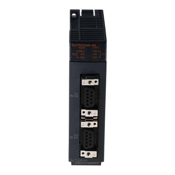
Page 10: Part Names
QJ71C24-R2 ( 2) *1: The appearance of the QJ71C24 is almost the same as that of the QJ71C24N, except for the model name part and serial number plate. *2: The appearance of the QJ71C24-R2 is almost the same as that of the QJ71C24N-R2, except for the model name part and serial number plate. - Page 11 (1) LED display list QJ71C24N QJ71C24N-R2 QJ71C24N-R4 ERR. ERR. ERR. NEU. NEU. NEU. NEU. NEU. NEU. Compatible protocol Display On/flashing Non- contents Bidirectional procedural Normal operation Normal Faulty or reset Valid display Error display Error has ERR. Normal (*1) occurred...
-
Page 12: External Wiring
Clear to send RI(CI) Call Indicate 1: QJ71C24N, QJ71C24 : CH1 side, QJ71C24N-R2 QJ71C24-R2 : CH1/CH2 side The following RS-232 interface connector is used for the module. • DDK Ltd. 9-pin D-sub (female) screw type 17L-10090-27 (D9AC)(-FA) Use one of the following as a connector shell for the connection cable of the module side. - Page 13 (1) Connection example with an external device capable of turning on and off the CD signal (pin No. 1) The module Cable connection and signal direction External device (Connection example of full or half Signal Pin number Signal name duplex communication) name RD(RXD) RD(RXD)
- Page 14 (3) Connection precaution (a) Connect the FG signal and shield of the connection cable as indicated below: Connection method Remark Connect to the connector • Do not short the FG signal and SG signal FG signal enclosure of the module. of the connector cable.
-
Page 15: Connecting To The Rs-422/485 Line
QJ71C24 Frame ground 1 QJ71C24N, QJ71C24 : CH2 side, QJ71C24N-R4 : CH1/CH2 side 2 Connect the RS-422/485 line of QJ71C24N-R4 while paying full attention to the followings: 1) Use the RS-422/485 cable recommended in chapter 2. Performance specifications. Be sure to strip the outer insulation layer by 7mm before connecting the cable to the plug-in socket block. - Page 16 POINT If the module is the first or last station on the RS-422/485 line, connect the following terminal resistor to the RS-422/485 interface with reference to the examples shown below. Data communication will be disturbed if a terminal resistor is not used. •...
- Page 17 (3) Example of one-to-n connection between external devices and the module (RS-485) C24 1) External device 1) External device 2) External device n RS-422/485 RS-422/485 RS-422/485 cable cable cable Terminal registor (4) Example of m-to-n connection between external devices and the modules (RS-485) C24n External device 1)
- Page 18 On the external device side, however, follow the instruction manual of the external device. Be sure to use the plate terminals included with the product when connecting the braided shield wire to the QJ71C24N-R4. Connect the FG of the module to the FG terminal of the power supply •...
-
Page 19: Settings For Gx Developer
6. Settings for GX Developer To use a serial communication module, set the intelligent function module switches of GX Developer as follows: (1) Switch 1 to 5 Set the transmission specifications and communication protocol of each interface using the combinations of setting values for each switch with 16 bit binary data according to the following table. - Page 20 When connecting external devices to both of two interfaces, the total of the communication speed should be 115200bps or less (230400 bps or less in the case of the QJ71C24N(-R2/R4)). When connecting an external device to either of two interfaces, the maximum of 115200 bps is available for the interface (the maximum of 230400 bps in the case of the QJ71C24N(-R2/R4)).
- Page 21 Do not use the above settings for the following cases, because linked operation cannot be performed. 1) When using the QJ71C24N-R2 or QJ71C24-R2. 2) When an external device is not connected to either of the interfaces. 3) When the bidirectional protocol is used for data communication.
-
Page 22: External Dimensions
7. External Dimensions (1) QJ71C24N, QJ71C24 The external dimensions of the QJ71C24 are almost the same as those of the QJ71C24N, except for the model name part and serial number plate. Outside cable diameter 4 + 10 ( 2) ( 1) ( 3) 23 (0.91) - Page 23 (3) QJ71C24N-R4 ( 1) ( 2) 23 (0.91) 90 (3.54) 27.4 (1.08) 11.5 (Unit: mm (in.)) (0.45) 1: R3 (Bending radius near the plug-in socket block) : Outside cable diameter 2: r2 (Bending radius near the wire connection) : Connectable as long as not...
- Page 24 Warranty Mitsubishi will not be held liable for damage caused by factors found not to be the cause of Mitsubishi; machine damage or lost profits caused by faults in the Mitsubishi products; damage, secondary damage, accident compensation caused by special factors unpredictable by Mitsubishi;...