Sign In
Upload
Manuals
Brands
WAGO Manuals
Control Unit
750-451
WAGO 750-451 Manuals
Manuals and User Guides for WAGO 750-451. We have
2
WAGO 750-451 manuals available for free PDF download: Manual
WAGO 750-451 Manual (116 pages)
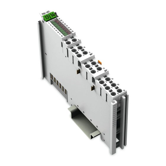
8 AI RTD 8-Channel Analog Input Module for Resistance Sensors
Brand:
WAGO
| Category:
Control Unit
| Size: 4.48 MB
Table of Contents
Deutsch
5
Table of Contents
3
Table of Contents
5
1 Notes about this Documentation
6
Validity of this Documentation
6
Copyright
6
Symbols
7
Number Notation
9
Font Conventions
9
Table 1: Number Notation
9
Table 2: Font Conventions
9
2 Important Notes
10
Legal Bases
10
Subject to Changes
10
Personnel Qualifications
10
Use of the WAGO-I/O-SYSTEM 750 in Compliance with Underlying Provisions
10
Technical Condition of Specified Devices
11
Safety Advice (Precautions)
12
3 Device Description
14
View
15
Table 3: Legend for Figure "View
15
Connectors
16
Data Contacts/Internal Bus
16
Power Jumper Contacts/Field Supply
17
Table 4: Legend for Figure "Power Jumper Contacts
17
Push-In CAGE CLAMP ® Connectors
18
Table 5: Legend for Figure "Push-In CAGE CLAMP ® Connectors" - 8- Channel, 2-Wire
18
Display Elements
19
Table 6: Legend for Figure "Display Elements
19
Operating Elements
20
Schematic Diagram
20
Technical Data
21
Device Data
21
Power Supply
21
Communication
21
Table 7: Technical Data - Device
21
Table 8: Technical Data - Power Supply
21
Table 9: Technical Data - Communication
21
Inputs
22
Measuring Accuracy at 25 °C
22
Table 10: Technical Data - Inputs
22
Table 11: Technical Data - Measuring Accuracy at 25 °C Ambient Temperature
22
Connection Type
23
Climatic Environmental Conditions
23
Table 12: Technical Data - Field Wiring
23
Table 13: Technical Data - Power Jumper Contacts
23
Table 14: Technical Data - Data Contacts
23
Table 15: Technical Data - Climatic Environmental Conditions
23
Approvals
24
Standards and Guidelines
25
4 Process Image
26
Overview
26
Control Bytes and Status Bytes
26
Table 16: Process Image
26
Table 17: Control Byte
27
Table 18: Status Byte
27
Process Data
28
Overview of Sensor Types
28
Table 19: Process Data, Overview in Standard Format and S5-FB250 Format
28
Pt100 (IEC 751), ID 0
29
Default Format
29
Table 20: ID 0, Setting Pt100 (IEC 751), Standard Format
29
S5-FB250 Format
30
Table 21: ID 0, Setting Pt100 (IEC 751), S5-FB250 Format
30
Ni100 (DIN 43760), ID 1
31
Default Format
31
Table 22: ID 1, Setting Ni100 (DIN 43760), Standard Format
31
S5-FB250 Format
32
Table 23: ID 1, Setting Ni100 (DIN 43760), S5-FB250 Format
32
Pt1000 (IEC 751), ID 2
33
Default Format
33
Table 24: ID 2, Setting Pt1000 (IEC 751), Standard Format
33
S5-FB250 Format
34
Table 25: ID 2, Setting Pt1000 (IEC 751), S5-FB250 Format
34
Pt500 (IEC 751), ID 3
35
Default Format
35
Table 26: ID 3, Setting Pt500 (IEC 751), Standard Format
35
S5-FB250 Format
36
Table 27: ID 3, Setting Pt500 (IEC 751), S5-FB250 Format
36
Pt200 (IEC 751), ID 4
37
Default Format
37
Table 28: ID 4, Setting Pt200 (IEC 751), Standard Format
37
S5-FB250 Format
38
Table 29: ID 4, Setting Pt200 (IEC 751), S5-FB250 Format
38
Ni1000 (TK6180, DIN 43760), ID 5
39
Default Format
39
Table 30: ID 5, Setting Ni1000 (TK6180, DIN 43760), Standard Format
39
S5-FB250 Format
40
Table 31: ID 5, Setting Ni1000 (TK6180, DIN 43760), S5-FB250 Format
40
Ni120 (Minco), ID 6
41
Default Format
41
Table 32: ID 6, Setting Ni120 (Minco), Standard Format
41
S5-FB250 Format
42
Table 33: ID 6, Setting Ni120 (Minco), S5-FB250 Format
42
Ni1000 (TK5000), ID 7
43
Default Format
43
Table 34: ID 7, Setting Ni1000 (TK5000), Standard Format
43
S5-FB250 Format
44
Table 35: ID 7, Setting Ni1000 (TK5000), S5-FB250 Format
44
Ni1000 (TK6180, DIN 43760), High-Resolution, ID 8
45
Default Format
45
Table 36: ID 8, Setting Ni1000 (TK6180, DIN 43760), Standard Format
45
S5-FB250 Format
46
Table 37: ID 8, Setting Ni1000 (DIN 43760), S5-FB250 Format
46
Ni1000 (TK5000), High-Resolution, ID 9
47
Default Format
47
Table 38: ID 9, Setting Ni1000 (TK5000), Standard Format
47
S5-FB250 Format
48
Table 39: ID 9, Setting Ni1000 (TK5000), S5-FB250 Format
48
Pt1000 (IEC 751), High-Resolution, ID 10
49
Default Format
49
Table 40: ID 10, Setting Pt1000 (IEC 751), Standard Format
49
S5-FB250 Format
50
Table 41: ID 10, Setting Pt1000 (IEC 751), S5-FB250 Format
50
Resistance Measurement 1, 0 Ohm
51
Default Format
51
Table 42: ID 14, Setting "Resistance Measurement 1", Standard Format
51
S5-FB250 Format
52
Resistance Measurement 2, 0 Ohm
52
Default Format
52
Table 43: ID 14, Setting "Resistance Measurement 1", S5-FB250 Format
52
S5-FB250 Format
53
Table 44: ID 15, Setting "Resistance Measurement 2", Standard Format
53
Table 45: ID 15, Setting "Resistance Measurement 2", S5-FB250 Format
53
5 Mounting
55
Mounting Sequence
55
Inserting and Removing Devices
56
Inserting the I/O Module
56
Removing the I/O Module
57
6 Connect Devices
58
Connecting a Conductor to the Push-In CAGE CLAMP
58
Connection Examples
59
2-Wire
59
7 Commissioning
60
Parameterization Via Register Communication
60
Register Assignment
62
Table 46: Register 6
62
Table 47: Register 32
63
Table 48: Register 35
64
Table 49: Register 36
65
Table 50: Register 37
65
Table 51: Register 38
66
Table 52: Register 39
66
Table 53: Register 40
66
Table 54: Register 41
67
Table 55: Register 42
67
Control and Status Bytes During Register Communication
68
Table 56: Register 43
68
Table 57: Control Byte CH1_C0 During Register Communication
68
Table 58: Status Byte CH1_S0 During Register Communication
68
Parameterization with WAGO-I/O-CHECK
69
Parameterization Dialog
71
Toolbar
71
Ai Rtd
72
7.2.1.1.1 Main Menu
72
Table 59: Buttons on the Main Menu
72
7.2.1.1.2 Application Menu
73
Table 60: Buttons in the Application Menu
73
Navigation Area
74
Application Area
75
7.2.1.3.1 "Settings" Menu Item
76
Figure 17: "Settings" > "Module" Menu Item
76
Table 61: "Settings" > "Module" Menu Item
77
Figure 18: "Settings" Menu Item
78
Table 62: "Settings" Menu Item
79
7.2.1.3.2 "Scaling" Menu Item
81
Figure 19: "Scaling" Menu Item
81
Table 63: "Scaling" > "Channel 1
81
7.2.1.3.3 Application Examples of Scaling
82
Table 64: Examples of a Scaled Process Value, Standard Format, Pt100
83
Table 65: Examples of a Scaled Process Value, S5-FB250 Format, Pt100
83
Table 66: Examples of a Scaled Process Value, Standard Format, Resistance
84
Table 67: Examples of a Scaled Process Value, S5-FB250 Format, Resistance
84
7.2.1.3.4 "Open Parameter File" Menu Item
85
7.2.1.3.5 "Save Parameter File" Menu Item
85
7.2.1.3.6 "Calibration" Menu Item
86
Figure 20: "Calibration" Menu Item
86
7.2.1.3.7 Application Example of Calibration
87
Table 68: "Calibration" Menu Item
87
Status Bar
89
Configuration and Parameterization Using a GSD File with PROFIBUS DP and PROFINET IO
90
8 Diagnostics
91
Error Response
91
Table 69: Prioritylevels of Diagnostic Functions
91
Table 70: Behavior in the Event of an Error Dependent on the Configuration
91
9 Appendix
93
Configuration and Parameterization Using a GSD File with PROFIBUS DP and PROFINET IO
93
Configuration 8 AI RTD
93
PROFIBUS DP (750-333, 750-833) Fieldbus Coupler PROFINET IO (750-370) Fieldbus Coupler
93
PROFINET IO (750-375, 750-377) Fieldbus Coupler
93
Table 71: Configuration
93
Table 72: Configuration
93
Parameterization 8 AI RTD
94
All PROFIBUS DP and PROFINET IO Fieldbus Couplers
96
Table 73: Specific Module / Channel Parameters for 75X-451
96
PROFIBUS DP (750-333, 750-833) Fieldbus Coupler
97
Table 74: General Module / Channel Parameters
97
PROFINET IO (750-370, 750-375, 750-377) Fieldbus Coupler
98
Table 75: General Module / Channel Parameters
98
10 Use in Hazardous Environments
100
Marking Configuration Examples
101
Marking for Europe According to ATEX and IEC-Ex
101
Table 76: Description of Marking Example for Approved I/O Modules According to ATEX and Iecex
102
Table 77: Description of Marking Example for Approved Ex I I/O Modules According to ATEX and Iecex
105
Marking for America According to NEC 500
106
Table 78: Description of Marking Example for Approved I/O Modules
106
Installation Regulations
107
Special Conditions for Safe Use (TÜV 14 ATEX 148929 X)
108
Special Conditions for Safe Use (ATEX Certificate TÜV 12 ATEX 106032 X)
109
Special Conditions for Safe Use (IEC-Ex Certificate TUN 14.0035X)
110
Special Conditions for Safe Use (IEC-Ex Certificate Iecex TUN 12.0039 X)
111
Special Conditions for Safe Use According to ANSI/ISA
112
English
113
Figure 1: View
15
Figure 4: Push-In CAGE CLAMP ® Connectors
15
Figure 2: Data Contacts
16
Figure 3: Power Jumper Contacts
17
Figure 5: Display Elements
19
Figure 6: Schematic Diagram
20
Figure 7: Insert I/O Module (Example)
56
Figure 8: Snap the I/O Module into Place (Example)
56
Figure 9: Removing the I/O Module (Example)
57
Figure 10: Connecting a Conductor to a Push-In CAGE CLAMP
58
Figure 11: Connection Example, 750-451, 8-Channel, 8 × 2-Wire
59
Figure 12: WAGO-I/O-CHECK User Interface
70
Figure 13: Parameterization Dialog for the I/O Module
71
Figure 14: Buttons in the Main Menu
72
Figure 15: Buttons in the Application Menu
73
Figure 16: Display of Measured Values in the Application Area
75
Figure 21: Example of the PROFIBUS DP Fieldbus Coupler Parameterization
94
Figure 22: Example of the 750-370 Fieldbus Coupler Parameterization Dialog
95
Figure 23: Example of the 750-375 and 750-377 Fieldbus Coupler
96
Figure 24: Side Marking Example for Approved I/O Modules According to ATEX and Iecex
101
Figure 25: Text Detail - Marking Example for Approved I/O Modules According to ATEX and Iecex
101
Figure 26: Side Marking Example for Approved Ex I I/O Modules According to ATEX and Iecex
103
Figure 27: Text Detail - Marking Example for Approved Ex I I/O Modules According to ATEX and Iecex
103
Figure 28: Side Marking Example for I/O Modules According to NEC 500
106
Figure 29: Text Detail - Marking Example for Approved I/O Modules
106
List of Figures
113
List of Tables
114
Advertisement
WAGO 750-451 Manual (112 pages)
8-Channel Analog Input Module for Resistance Sensors For WAGO-I/O-SYSTEM 750
Brand:
WAGO
| Category:
Control Unit
| Size: 4.03 MB
Table of Contents
Table of Contents
3
1 Notes about this Documentation
6
Validity of this Documentation
6
Revision History
6
Table 1: Variants
6
Table 2: Revision History
6
Copyright
7
Symbols
8
Number Notation
10
Font Conventions
10
Table 3: Number Notation
10
Table 4: Font Conventions
10
2 Important Notes
11
Legal Bases
11
Subject to Changes
11
Personnel Qualifications
11
Use of the 750 Series in Compliance with Underlying Provisions
11
Technical Condition of Specified Devices
12
Disposal
12
2.1.4.1.1 Electrical and Electronic Equipment
12
2.1.4.1.2 Packaging
13
Safety Advice (Precautions)
14
3 Device Description
16
Table 5: Compatibility List 750-451
17
View
18
Figure 1: View
18
Table 6: Legend for Figure "View
18
Connectors
19
Data Contacts/Local Bus
19
Figure 2: Data Contacts
19
Power Jumper Contacts/Field Supply
20
Figure 3: Power Jumper Contacts
20
Table 7: Legend for Figure "Power Jumper Contacts
20
Push-In CAGE CLAMP ® Connectors
21
Figure 4: Push-In CAGE CLAMP ® Connectors
21
Table 8: Legend for Figure "Push-In CAGE CLAMP ® Connectors
21
Display Elements
22
Figure 5: Display Elements
22
Table 9: Legend for Figure "Display Elements
22
Operating Elements
23
Schematic Diagram
23
Figure 6: Schematic Diagram
23
Technical Data
24
Device Data
24
Power Supply
24
Communication
24
Table 10: Technical Data - Device
24
Table 11: Technical Data - Power Supply
24
Table 12: Technical Data - Communication
24
Inputs
25
Measuring Accuracy at 25 °C
25
Table 13: Technical Data - Inputs
25
Table 14: Technical Data - Measuring Accuracy at 25 °C Ambient Temperature
25
Connection Type
26
Climatic Environmental Conditions
26
Table 15: Technical Data - Field Wiring
26
Table 16: Technical Data - Power Jumper Contacts
26
Table 17: Technical Data - Data Contacts
26
Table 18: Technical Data - Climatic Environmental Conditions
26
Approvals
27
Standards and Guidelines
28
4 Process Image
29
Overview
29
Table 19: Process Image
29
Control Bytes and Status Bytes
30
Table 20: Control Byte
30
Table 21: Status Byte
31
Process Data
32
Overview of Sensor Types
32
Table 22: Process Data, Overview in Standard Format and S5-FB250 Format
32
Pt100 (IEC 751), ID 0
33
Default Format
33
Table 23: ID 0, Setting Pt100 (IEC 751), Standard Format
33
S5-FB250 Format
34
Table 24: ID 0, Setting Pt100 (IEC 751), S5-FB250 Format
34
Ni100 (DIN 43760), ID 1
35
Default Format
35
Table 25: ID 1, Setting Ni100 (DIN 43760), Standard Format
35
S5-FB250 Format
36
Table 26: ID 1, Setting Ni100 (DIN 43760), S5-FB250 Format
36
Pt1000 (IEC 751), ID 2
37
Default Format
37
Table 27: ID 2, Setting Pt1000 (IEC 751), Standard Format
37
S5-FB250 Format
38
Table 28: ID 2, Setting Pt1000 (IEC 751), S5-FB250 Format
38
Pt500 (IEC 751), ID 3
39
Default Format
39
Table 29: ID 3, Setting Pt500 (IEC 751), Standard Format
39
S5-FB250 Format
40
Table 30: ID 3, Setting Pt500 (IEC 751), S5-FB250 Format
40
Pt200 (IEC 751), ID 4
41
Default Format
41
Table 31: ID 4, Setting Pt200 (IEC 751), Standard Format
41
S5-FB250 Format
42
Table 32: ID 4, Setting Pt200 (IEC 751), S5-FB250 Format
42
Ni1000 (TK6180, DIN 43760), ID 5
43
Default Format
43
Table 33: ID 5, Setting Ni1000 (TK6180, DIN 43760), Standard Format
43
S5-FB250 Format
44
Table 34: ID 5, Setting Ni1000 (TK6180, DIN 43760), S5-FB250 Format
44
Ni120 (Minco), ID 6
45
Default Format
45
Table 35: ID 6, Setting Ni120 (Minco), Standard Format
45
S5-FB250 Format
46
Table 36: ID 6, Setting Ni120 (Minco), S5-FB250 Format
46
Ni1000 (TK5000), ID 7
47
Default Format
47
Table 37: ID 7, Setting Ni1000 (TK5000), Standard Format
47
S5-FB250 Format
48
Table 38: ID 7, Setting Ni1000 (TK5000), S5-FB250 Format
48
Ni1000 (TK6180, DIN 43760), High-Resolution, ID 8
49
Default Format
49
Table 39: ID 8, Setting Ni1000 (TK6180, DIN 43760), Standard Format
49
S5-FB250 Format
50
Table 40: ID 8, Setting Ni1000 (DIN 43760), S5-FB250 Format
50
Ni1000 (TK5000), High-Resolution, ID 9
51
Default Format
51
Table 41: ID 9, Setting Ni1000 (TK5000), Standard Format
51
S5-FB250 Format
52
Table 42: ID 9, Setting Ni1000 (TK5000), S5-FB250 Format
52
Pt1000 (IEC 751), High-Resolution, ID 10
53
Default Format
53
Table 43: ID 10, Setting Pt1000 (IEC 751), Standard Format
53
S5-FB250 Format
54
Table 44: ID 10, Setting Pt1000 (IEC 751), S5-FB250 Format
54
Pt100 (IEC 751), High-Resolution, ID 11
55
Standard Format
55
Table 45: ID 11, Pt100 Setting (IEC 751), Standard Format
55
S5-FB250 Format
56
Table 46: ID 11, Pt100 (IEC 751) Setting, S5-FB250 Format
56
Resistance Measurement 1, 0 Ohm
57
Default Format
57
Table 47: ID 14, Setting "Resistance Measurement 1", Standard Format
57
S5-FB250 Format
58
Table 48: ID 14, Setting "Resistance Measurement 1", S5-FB250 Format
58
Resistance Measurement 2, 0 Ohm
59
Default Format
59
Table 49: ID 15, Setting "Resistance Measurement 2", Standard Format
59
S5-FB250 Format
60
Table 50: ID 15, Setting "Resistance Measurement 2", S5-FB250 Format
60
5 Mounting
61
Mounting Sequence
61
Inserting and Removing Devices
62
Inserting the I/O Module
62
Figure 7: Insert I/O Module (Example)
62
Figure 8: Snap the I/O Module into Place (Example)
62
Removing the I/O Module
63
Figure 9: Removing the I/O Module (Example)
63
6 Connect Devices
64
Connecting a Conductor to the Push-In CAGE CLAMP
64
Figure 10: Connecting a Conductor to a Push-In CAGE CLAMP
64
Connection Examples
65
2-Wire
65
Figure 11: Connection Example, 750-451, 8-Channel, 8 × 2-Wire
65
7 Commissioning
66
Parameterization with WAGO-I/O-CHECK
66
Figure 12: WAGO-I/O-CHECK User Interface
67
Parameterization Dialog
68
Toolbar
68
Figure 13: Parameterization Dialog for the I/O Module
68
7.1.1.1.1 Main Menu
69
Figure 14: Buttons in the Main Menu
69
Table 51: Buttons on the Main Menu
69
7.1.1.1.2 Application Menu
70
Figure 15: Buttons in the Application Menu
70
Table 52: Buttons in the Application Menu
70
Navigation Area
71
Application Area
72
Figure 16: Display of Measured Values in the Application Area
72
7.1.1.3.1 Importing/Exporting Parameter File
73
Figure 17: "Settings" Menu Item Warning Message
73
Table 53: Buttons in the "Settings" and "Scaling" Menus
73
Table 54: Buttons in the "Settings" Menu
73
7.1.1.3.2 "Settings" Menu Item
74
Figure 18: "Settings" > "Module" Menu Item
74
Table 55: "Settings" > "Module" Menu Item
75
Figure 19: "Settings" > "Channel" Menu Item
76
Table 56: "Settings" Menu Item
77
7.1.1.3.3 "Scaling" Menu Item
79
Figure 20: "Scaling" Menu Item
79
Table 57: "Scaling" > "Channel 1
80
7.1.1.3.4 Application Examples of Scaling
81
Table 58: Examples of a Scaled Process Value, Standard Format
81
Table 59: Examples of a Scaled Process Value, S5-FB250 Format
81
Table 60: Examples of a Scaled Process Value, Standard Format
82
Table 61: Examples of a Scaled Process Value, S5-FB250 Format
82
7.1.1.3.5 "Calibration" Menu Item
83
Figure 21: "Calibration" Menu Item
83
7.1.1.3.6 Application Example of Calibration
84
Table 62: "Calibration" Menu Item
84
Status Bar
86
Configuration and Parameterization Using a GSD File with PROFIBUS DP and PROFINET IO
87
8 Diagnostics
88
Error Response
88
Table 63: Prioritylevels of Diagnostic Functions
88
Table 64: Behavior in the Event of an Error Dependent on the Configuration
88
9 Appendix
90
Configuration and Parameterization Using a GSD File with PROFIBUS DP and PROFINET IO
90
Configuration 8 AI RTD
90
PROFIBUS DP (750-333, 750-833) Fieldbus Coupler PROFINET IO (750-370) Fieldbus Coupler
90
PROFINET IO (750-375, 750-377) Fieldbus Coupler
90
Table 65: Configuration
90
Table 66: Configuration
90
Parameterization 8 AI RTD
91
Figure 22: Example of the PROFIBUS DP Fieldbus Coupler Parameterization
91
Figure 23: Example of the 750-370 Fieldbus Coupler Parameterization Dialog
92
Figure 24: Example of the 750-375 and 750-377 Fieldbus Coupler
93
All PROFIBUS DP and PROFINET IO Fieldbus Couplers
94
Table 67: Specific Module / Channel Parameters for 75X-451
94
PROFIBUS DP (750-333, 750-833) Fieldbus Coupler
95
PROFINET IO (750-370, 750-375, 750-377) Fieldbus Coupler
95
Table 68: General Module / Channel Parameters
95
Table 69: General Module / Channel Parameters
95
10 Use in Hazardous Environments
97
Marking Configuration Examples
98
Marking for Europe According to ATEX and Iecex
98
Figure 25: Marking Example According to ATEX and Iecex
98
Figure 26: Text Detail - Marking Example According to ATEX and Iecex
98
Table 70: Description of Marking Example According to ATEX and Iecex
99
Figure 27: Marking Example for Approved Ex I I/O Module According to
100
Figure 28: Text Detail - Marking Example for Approved Ex I I/O Module
100
Table 71: Description of Marking Example for Approved Ex I I/O Module According to ATEX and Iecex
101
Table 73: Description of Marking Example for Approved Ex I I/O Module
101
Marking for the United States of America (NEC) and Canada (CEC)
102
Figure 29: Marking Example According to NEC
102
Figure 30: Text Detail - Marking Example According to NEC 500
102
Table 72: Description of Marking Example According to NEC 500
102
Figure 31: Text Detail - Marking Example for Approved Ex I I/O Module
103
Figure 32: Text Detail - Marking Example for Approved Ex I I/O Module
103
Table 74: Description of Marking Example for Approved Ex I I/O Modules
103
Figure 33: Text Detail - Marking Example for Approved Ex I I/O Modules
104
Table 75: Description of Marking Example for Approved Ex I I/O Modules
104
Installation Regulations
105
Special Notes Regarding Explosion Protection
105
Special Notes Regarding ANSI/ISA Ex
107
List of Figures
108
List of Tables
109
Advertisement
Related Products
WAGO 750-453/040-000
WAGO 750-457/040-000
WAGO 750-458
WAGO 750-451/025-000
WAGO 750-450
WAGO 750-494 Series
WAGO 750-494/025-000
WAGO 750-481/040-000
WAGO 750-431/040-000
WAGO 750-404/040-003
WAGO Categories
I/O Systems
Control Unit
Power Supply
Switch
Controller
More WAGO Manuals
Login
Sign In
OR
Sign in with Facebook
Sign in with Google
Upload manual
Upload from disk
Upload from URL