Sign In
Upload
Manuals
Brands
WAGO Manuals
Control Unit
750-458
User Manuals: WAGO 750-458 analog input Thermocouple
Manuals and User Guides for WAGO 750-458 analog input Thermocouple. We have
1
WAGO 750-458 analog input Thermocouple manual available for free PDF download: Manual
WAGO 750-458 Manual (104 pages)
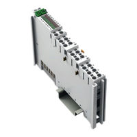
8AI; TC; Adjust, 8-Channel Analog Input Module; Thermocouple; Adjustable
Brand:
WAGO
| Category:
Control Unit
| Size: 2 MB
Table of Contents
Table of Contents
5
Table of Contents
3
1 Notes about this Documentation
6
Validity of this Documentation
6
Revision History
6
Copyright
6
Table 1: Revision History
6
Symbols
7
Number Notation
9
Font Conventions
9
Table 2: Number Notation
9
Table 3: Font Conventions
9
2 Important Notes
10
Legal Bases
10
Subject to Changes
10
Personnel Qualifications
10
Use of the WAGO-I/O-SYSTEM 750 in Compliance with Underlying Provisions
10
Technical Condition of Specified Devices
11
Safety Advice (Precautions)
12
3 Device Description
14
Table 4: Compatibility List 750-458
15
View
16
Figure 1: View of Device
16
Table 5: Legend for Figure "View
16
Connectors
17
Data Contacts/Local Bus
17
Figure 2: Data Contacts
17
Power Jumper Contacts/Field Supply
18
Figure 3: Power Jumper Contacts
18
Table 6: Legend for Figure "Power Jumper Contacts
18
Push-In CAGE CLAMP ® Connectors
19
Figure 4: Push-In CAGE CLAMP ® Connections
19
Table 7: Legend for the "Push-In CAGE CLAMP ® Connections" Figure
20
Display Elements
21
Figure 5: Display Elements
21
Table :8 Legend for the "Display Elements" Figure
21
Operating Elements
22
Schematic Diagram
23
Figure 6: Schematic Switching Diagram
23
Technical Data
24
Device Data
24
Power Supply
24
Table 9: Technical Data, Device
24
Table 10: Technical Data, Power Supply
24
Inputs
25
Table 11: Technical Data, Inputs
25
Sensor Types and Measuring Accuracies at 25 °C Ambient Temperature
26
Table 12: Technical Data - Sensor Types and Measuring Accuracies at 25 °C
26
Communication
27
Connection Type
27
Climatic Environmental Conditions
27
Table 13: Technical Data, Communication
27
Table 14: Technical Data - Field Wiring
27
Table 15: Technical Data - Power Jumper Contacts
27
Table 16: Technical Data - Data Contacts
27
Table 17: Technical Data - Climatic Environmental Conditions
27
Approvals
28
Standards and Guidelines
30
4 Process Image
31
Overview
32
Table 18: Process Image - I/O Module 750-458
32
Status Bytes
33
Table 19: Status Byte CH1_S0
33
Process Data
34
Overview of Sensor Types
34
Table 20: Overview of Sensor Types
34
Sensors for Temperature Measurement (°C)
35
Standard Data Format
35
Table 21: Process Image Type E, ID0, Two's Complement Representation
35
Table 22: Process Image Type N, ID1, Two's Complement Representation
36
Table 23: Process Image Type J, ID2, Two's Complement Representation
37
Table 24: Process Image Type K, ID3, Two's Complement Representation
38
Table 25: Process Image Type S, ID4 and Type R, ID5, Two's Complement Representation
39
Table 26: Process Image Type B, ID6, Two's Complement Representation
39
Table 27: Process Image Type T, ID7, Two's Complement Representation
40
Table 28: Process Image Type C, ID8, Two's Complement Representation
41
Sensors for Voltage Measurement (MV)
42
Standard Data Format
42
Table 29: Process Image Voltage Measurement ±30 MV, ID9, Two's
42
Table 30: Process Image Voltage Measurement ±60 MV, ID10, Two's
43
Table 31: Process Image Voltage Measurement ±120 MV, ID11, Two's
44
Table 32: Process Image Voltage Measurement ±240 MV, ID12, Two's
45
5 Mounting
46
Mounting Sequence
46
Inserting and Removing Devices
47
Inserting the I/O Module
47
Figure 7: Insert I/O Module (Example)
47
Figure 8: Snap the I/O Module into Place (Example)
47
Removing the I/O Module
48
Figure 9: Removing the I/O Module (Example)
48
6 Connect Devices
49
Connecting a Conductor to the Push-In CAGE CLAMP
49
Figure 10: Connecting a Conductor to a Push-In CAGE CLAMP
49
Connection Example
50
Figure 11: Connection Example - 2-Wire
50
7 Commissioning
51
Parameterization with WAGO-I/O-CHECK
51
Figure 12: WAGO-I/O-CHECK User Interface
52
Parameterization Dialog
53
Figure 13: Parameterization Dialog for the I/O Module 750-458
53
Title Bar
54
Main Menu
54
Figure 14: Title Bar in the Parameterization Dialog
54
Table 33: Buttons in the Main Menu
54
Horizontal Tab Menu
55
Figure 15: Horizontal Tab Menu
55
7.1.1.3.1 "File" Tab
56
Figure 16: Buttons in the Application Menu
56
Table 34: Buttons in the Application Menu
56
Open" Menu Item
57
Save" Menu Item
57
7.1.1.3.2 "Start" Tab
58
Figure 17: Contents of the Horizontal Tab Start
58
Figure 18: Start > Main Menu > Channel Selection List
58
7.1.1.3.3 "Connection" Tab
59
Figure 19: Connection Tab for Disconnected I/O Module
59
Figure 20: Connection Tab for Connected I/O Module
59
Vertical Tab Menu
60
Figure 21: Overview of the Vertical Tab Menu
60
7.1.1.4.1 "Module Settings" Menu Item
61
Figure 22: Module Settings Menu Item View
61
Table 35: Module Settings Menu Item
61
7.1.1.4.2 "Channel Settings" Menu Item
62
Figure 23: Channel Settings Menu Item View
63
Table 36: Channel Settings Menu Item
64
7.1.1.4.3 "Scaling" Menu Item
65
Figure 24: Scaling Menu Item View
66
Table 37: Scaling Menu Item
67
7.1.1.4.4 "Calibration" Menu Item
68
Figure 25: Calibration Menu Item View
69
Table 38: Calibration Menu Item
70
7.1.1.4.5 "Monitoring" Menu Item
71
Figure 26: Monitoring Menu Item View
71
7.1.1.4.6 "Information" Menu Item
72
Table 39: Monitoring Menu Item
72
Application Area
73
Status Messages
73
Figure 27: Information Menu Item View
73
Figure 28: Expanding the Status Messages Window
74
Figure 29: Status Messages in the Application Window of the Parameterization
74
Status Bar
75
Configuration and Parameterization Using a GSD File with PROFIBUS DP and PROFINET IO
75
Figure 30: Status Bar in the Parameterization Dialog
75
Calibrating Measured Values
76
Table 40: Sensor Type Groups
76
Table 41: Variable Legend - Calibrating Measured Values
76
Example of Determining Gain and Offset
77
Scaling Measured Values
79
Table 42: Variable Legend - Scaling Measured Values
79
8 Diagnostics
80
I/O Module Behavior in the Event of an Error
80
Table 43: Priority Levels of Diagnostic Functions
80
Table 44: Behavior in the Event of an I/O Module Error Dependent on the
81
9 Use in Hazardous Environments
82
Marking Configuration Examples
83
Marking for Europe According to ATEX and Iecex
83
Figure 31: Marking Example According to ATEX and Iecex
83
Figure 32: Text Detail - Marking Example According to ATEX and Iecex
83
Table 45: Description of Marking Example According to ATEX and Iecex
84
Figure 33: Marking Example for Approved Ex I I/O Module According to ATEX
85
Figure 34: Text Detail - Marking Example for Approved Ex I I/O Module According to ATEX and Iecex
85
Marking for America (NEC) and Canada (CEC)
86
Table 46: Description of Marking Example for Approved Ex I I/O Module According to ATEX and Iecex
86
Table 48: Description of Marking Example for Approved Ex I I/O Module
86
Figure 35: Marking Example According to NEC
87
Figure 36: Text Detail - Marking Example According to NEC 500
87
Table 47: Description of Marking Example According to NEC 500
87
Figure 37: Text Detail - Marking Example for Approved Ex I I/O Module
88
Figure 38: Text Detail - Marking Example for Approved Ex I I/O Module
88
Table 49: Description of Marking Example for Approved Ex I I/O Modules
88
Figure 39: Text Detail - Marking Example for Approved Ex I I/O Modules
89
Table 50: Description of Marking Example for Approved Ex I I/O Modules
89
Installation Regulations
90
Special Notes Regarding Explosion Protection
90
Special Notes Regarding ANSI/ISA Ex
92
10 Appendix
93
Configuration and Parameterization Using a GSD File with PROFIBUS DP and PROFINET IO
93
Configuration 8 AI TC
93
PROFIBUS DP Fieldbus Coupler/Controller 750-333(/0Xx-000), 750-833(/0Xx-000)
93
PROFINET IO Fieldbus Coupler 750-370, 750-375(/025-000), 750-377(/025-000)
93
Table 51: Configuration PROFIBUS DP
93
Table 52: Configuration 750-370
93
Table 53: Configuration 750-375(/025-000), 750-377(/025-000)
93
Parameterization 8 AI TC
94
Figure 40: Example of the PROFIBUS DP Fieldbus Coupler Parameterization
94
All PROFIBUS DP and PROFINET IO Fieldbus Couplers
96
Table 54: Specific Module / Channel Parameters for 750-458
96
PROFIBUS DP Fieldbus Coupler 750-333(/0Xx-000), 750-833(/0Xx-000)
97
Table 55: General Module / Channel Parameters
97
PROFINET IO Fieldbus Coupler 750-370, 750-375(/025-000), 750-377(/025-000)
98
Table 56: General Module / Channel Parameters
98
List of Figures
100
List of Tables
102
Advertisement
Advertisement
Related Products
WAGO 750-451
WAGO 750-453/040-000
WAGO 750-457/040-000
WAGO 750-451/025-000
WAGO 750-450
WAGO 750-483/040-000
WAGO 750-482/000-001
WAGO 750-469/000-002
WAGO 750-469/000-012
WAGO 750-495/040-000
WAGO Categories
I/O Systems
Control Unit
Power Supply
Switch
Controller
More WAGO Manuals
Login
Sign In
OR
Sign in with Facebook
Sign in with Google
Upload manual
Upload from disk
Upload from URL