Sign In
Upload
Manuals
Brands
Texas Instruments Manuals
Microcontrollers
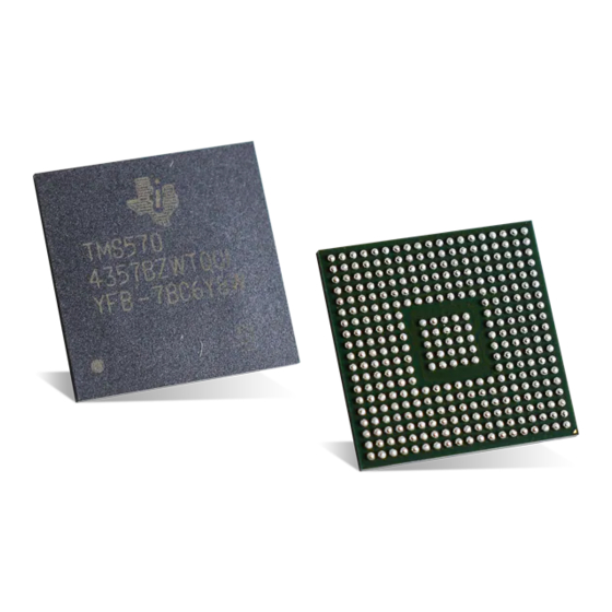
TMS570LC4357
Texas Instruments TMS570LC4357 Manuals
Manuals and User Guides for Texas Instruments TMS570LC4357. We have
1
Texas Instruments TMS570LC4357 manual available for free PDF download: Technical Reference Manual
Texas Instruments TMS570LC4357 Technical Reference Manual (2208 pages)
TMS570LC43 Series 16/32-Bit RISC Flash Microcontrollers
Brand:
Texas Instruments
| Category:
Microcontrollers
| Size: 14 MB
Table of Contents
Table of Contents
2
Preface
104
1 Introduction
106
Designed for Safety Applications
107
Family Description
108
Endianism Considerations
111
TMS570: Big Endian (BE32)
111
2 Architecture
112
Introduction
113
Architecture Block Diagram
113
Definitions of Terms
115
Bus Master / Slave Access Privileges
118
CPU Interconnect Subsystem SDC MMR Port
118
Interconnect Subsystem Runtime Status
119
Master ID to Pcrx
119
Memory Organization
120
Memory-Map Overview
120
Memory-Map Table
122
Flash on Microcontrollers
129
On-Chip SRAM
134
Exceptions
139
Resets
139
Aborts
139
System Software Interrupts
141
Clocks
142
Clock Sources
142
Clock Domains
143
Low Power Modes
145
Clock Test Mode
146
Embedded Trace Macrocell (ETM-R5)
148
Safety Considerations for Clocks
148
System and Peripheral Control Registers
151
Primary System Control Registers (SYS)
151
Secondary System Control Registers (SYS2)
205
Peripheral Central Resource (PCR) Control Registers
217
3 SCR Control Module (SCM)
252
Overview
253
Features
253
System Block Diagram
254
Module Operation
255
Block Diagram
255
Timeout Threshold Compare Block
255
SCM Control Block
256
How to Use SCM
257
How to Check the Parity Compare Logic
257
How to Initiate Self-Test Sequence
258
How to Configure Timeout Check
259
SCM Registers
260
SCM REVID Register (SCMREVID)
260
SCM Control Register (SCMCNTRL)
261
SCM Compare Threshold Counter Register (SCMTHRESHOLD)
262
SCM Initiator Error0 Status Register (SCMIAERR0STAT)
263
SCM Initiator Error1 Status Register (SCMIAERR1STAT)
263
SCM Initiator Active Status Register (SCMIASTAT)
264
SCM Target Active Status Register (SCMTASTAT)
264
4 Interconnect
265
Overview
266
Block Diagram
266
Peripheral Interconnect Subsystem
266
Accessing Pcrx and Crcx Slave
267
Accessing SDC MMR Port Slave
267
Accessing Other Slaves Via PS_SCR_S
267
CPU Interconnect Subsystem
268
Slave Accessing
268
ECC Generation and Evaluation
269
Safety Diagnostic Checker
269
Interconnect Self-Test
270
Interconnect Timeout
270
Interconnect Runtime Status
271
SDC MMR Registers
272
SDC Status Register (SDC_STATUS)
273
SDC Control Register (SDC_CONTROL)
274
Error Generic Parity Register (ERR_GENERIC_PARITY)
274
Error Unexpected Transaction Register (ERR_UNEXPECTED_TRANS)
275
Error Transaction ID Register (ERR_TRANS_ID)
275
Error Transaction Signature Register (ERR_TRANS_SIGNATURE)
276
Error Transaction Type Register (ERR_TRANS_TYPE)
276
Error User Parity Register (ERR_USER_PARITY)
277
Slave Error Unexpected Master ID Register (SERR_UNEXPECTED_MID)
277
Slave Error Address Decode Register (SERR_ADDR_DECODE)
278
Slave Error User Parity Register (SERR_USER_PARITY)
278
5 Power Management Module (PMM)
279
Overview
280
Features
280
Block Diagram
280
Power Domains
282
PMM Operation
283
Power Domain State
283
Default Power Domain State
283
Disabling a Power Domain Permanently
283
Changing Power Domain State
283
Reset Management
284
Diagnostic Power State Controller (PSCON)
284
PSCON Compare Block
284
PMM Registers
285
Logic Power Domain Control Register (LOGICPDPWRCTRL0)
286
Logic Power Domain Control Register (LOGICPDPWRCTRL1)
287
Power Domain Clock Disable Register (PDCLKDISREG)
288
Power Domain Clock Disable Set Register (PDCLKDISSETREG)
289
Power Domain Clock Disable Clear Register (PDCLKDISCLRREG)
290
Logic Power Domain PD2 Power Status Register (LOGICPDPWRSTAT0)
291
Logic Power Domain PD3 Power Status Register (LOGICPDPWRSTAT1)
292
Logic Power Domain PD4 Power Status Register (LOGICPDPWRSTAT2)
293
Logic Power Domain PD5 Power Status Register (LOGICPDPWRSTAT3)
294
Logic Power Domain PD6 Power Status Register (LOGICPDPWRSTAT4)
295
Global Control Register 1 (GLOBALCTRL1)
296
Global Status Register (GLOBALSTAT)
297
PSCON Diagnostic Compare Key Register (PRCKEYREG)
297
Logicpd PSCON Diagnostic Compare Status Register 1 (LPDDCSTAT1)
298
Logicpd PSCON Diagnostic Compare Status Register 2 (LPDDCSTAT2)
299
Isolation Diagnostic Status Register (ISODIAGSTAT)
300
6 I/O Multiplexing and Control Module (IOMM)
301
Overview
302
Main Features of I/O Multiplexing Module (IOMM)
302
Control of Multiplexed Outputs
302
Control of Multiplexed Inputs
303
Control of Special Multiplexed Options
312
Control of SDRAM Clock (EMIF_CLK)
314
Control for Other EMIF Outputs
314
Control of Ethernet Controller Mode
314
Control of ADC Trigger Events
314
Control for ADC Event Trigger Signal Generation from Epwmx Modules
315
Control for Generating Interrupt Upon External Fault Indication to N2Hetx
318
Control for Synchronizing Time Bases for All Epwmx Modules
320
Control for Synchronizing All Epwmx Modules to N2HET1 Module Time-Base
320
Control for Input Connections to Epwmx Modules
321
Control for Input Connections to Ecapx Modules
322
Control for Input Connections to Eqepx Modules
323
Selecting GIO Port for External DMA Request
325
Temperature Sensor Selection
326
Safety Features
327
Locking Mechanism for Memory-Mapped Registers
327
Error Conditions
327
IOMM Registers
328
REVISION_REG: Revision Register
328
BOOT_REG: Boot Mode Register
329
KICK_REG0: Kicker Register
330
KICK_REG1: Kicker Register 1
330
ERR_RAW_STATUS_REG: Error Raw Status / Set Register
331
ERR_ENABLED_STATUS_REG: Error Enabled Status / Clear Register
332
ERR_ENABLE_REG: Error Signaling Enable Register
333
ERR_ENABLE_CLR_REG: Error Signaling Enable Clear Register
334
FAULT_ADDRESS_REG: Fault Address Register
334
FAULT_STATUS_REG: Fault Status Register
335
FAULT_CLEAR_REG: Fault Clear Register
336
Pinmmrnn: Output Pin Multiplexing Control Registers
336
Pinmmrnn: Input Pin Multiplexing Control Registers
337
Pinmmrnn: Special Functionality Multiplexing Control Registers
337
7 F021 Level 2 Flash Module Controller (L2FMC)
338
Overview
339
Features
339
Definition of Terms
339
F021 Flash Tools
340
Default Flash Configuration
340
EEPROM Emulation Support
340
Secded
341
SECDED Initialization
341
ECC Encoding
341
Syndrome Table: Decode to Bit in Error
343
Syndrome Table: an Alternate Method
344
Memory Map
345
Location of Flash ECC Bits
345
OTP Memory
346
Power On, Power off Considerations
350
Error Checking at Power on
350
Flash Integrity at Power off
350
Emulation and SIL3 Diagnostic Modes
350
System Emulation
350
Diagnostic Mode
350
Diagnostic Mode Summary
352
SECDED Software Diagnostic
353
Read Margin
353
Parameter Overlay Module (POM)
353
Example Procedure to Configure the POM
353
Summary of L2FMC Errors
354
Flash Control Registers
355
Flash Read Control Register (FRDCNTL)
356
Read Margin Control Register (FSPRD)
357
EEPROM Error Correction Control Register (EE_FEDACCTRL1)
358
Flash Port a Error and Status Register (FEDAC_PASTATUS)
359
Flash Port B Error and Status Register (FEDAC_PBSTATUS)
360
Flash Global Error and Status Register (FEDAC_GBLSTATUS)
361
Flash Error Detection and Correction Sector Disable Register (FEDACSDIS)
362
Primary Address Tag Register (FPRIM_ADD_TAG)
363
Duplicate Address Tag Register (FDUP_ADD_TAG)
363
Flash Bank Protection Register (FBPROT)
364
Flash Bank Sector Enable Register (FBSE)
364
Flash Bank Busy Register (FBBUSY)
365
Flash Bank Access Control Register (FBAC)
365
Flash Bank Power Mode Register (FBPWRMODE)
366
Flash Bank/Pump Ready Register (FBPRDY)
367
Flash Pump Access Control Register 1 (FPAC1)
368
Flash Module Access Control Register (FMAC)
369
Flash Module Status Register (FMSTAT)
370
EEPROM Emulation Data MSW Register (FEMU_DMSW)
372
EEPROM Emulation Data LSW Register (FEMU_DLSW)
372
EEPROM Emulation ECC Register (FEMU_ECC)
373
Flash Lock Register (FLOCK)
373
Diagnostic Control Register (FDIAGCTRL)
374
Raw Address Register (FRAW_ADDR)
375
Parity Override Register (FPAR_OVR)
376
Reset Configuration Valid Register (RCR_VALID)
377
Crossbar Access Time Threshold Register (ACC_THRESHOLD)
377
Flash Error Detection and Correction Sector Disable Register 2 (FEDACSDIS2)
378
Lower Word of Reset Configuration Read Register (RCR_VALUE0)
379
Upper Word of Reset Configuration Read Register (RCR_VALUE1)
379
FSM Register Write Enable Register (FSM_WR_ENA)
380
EEPROM Emulation Configuration Register (EEPROM_CONFIG)
380
FSM Sector Register 1 (FSM_SECTOR1)
381
FSM Sector Register 2 (FSM_SECTOR2)
381
Flash Bank Configuration Register (FCFG_BANK)
382
POM Control Registers
383
POM Global Control Register (POMGLBCTRL)
383
POM Revision ID Register (POMREV)
384
POM Flag Register (POMFLG)
384
POM Region Start Address Register (Pomprogstartx)
385
POM Overlay Region Start Address Register (Pomovlstartx)
385
POM Region Size Register (Pomregsizex)
386
8 Level 2 RAM (L2RAMW) Module
387
Overview
388
Module Operation
388
RAM Memory Map
388
Safety Features
389
L2RAMW Auto-Initialization
392
Trace Module Support
392
Emulation/Debug Mode Behavior
392
Diagnostic Test Procedure
392
Control and Status Registers
393
L2RAMW Module Control Register (RAMCTRL)
393
L2RAMW Error Status Register (RAMERRSTATUS)
395
L2RAMW Diagnostic Data Vector High Register (DIAG_DATA_VECTOR_H)
398
L2RAMW Diagnostic Data Vector Low Register (DIAG_DATA_VECTOR_L)
398
L2RAMW Diagnostic ECC Vector Register (DIAG_ECC)
399
L2RAMW RAM Test Mode Control Register (RAMTEST)
400
L2RAMW RAM Address Decode Vector Test Register (RAMADDRDEC_VECT)
401
L2RAMW Memory Initialization Domain Register (MEMINIT_DOMAIN)
402
L2RAMW Bank to Domain Mapping Register0 (BANK_DOMAIN_MAP0)
403
L2RAMW Bank to Domain Mapping Register1 (BANK_DOMAIN_MAP1)
404
9 Programmable Built-In Self-Test (PBIST) Module
405
Overview
406
Features of PBIST
406
PBIST Vs. Application Software-Based Testing
406
PBIST Block Diagram
406
RAM Grouping and Algorithm
407
PBIST Flow
408
PBIST Sequence
409
Memory Test Algorithms on the On-Chip ROM
411
PBIST Control Registers
412
RAM Configuration Register (RAMT)
413
Datalogger Register (DLR)
414
PBIST Activate/Clock Enable Register (PACT)
415
PBIST ID Register
416
Override Register (OVER)
417
Fail Status Fail Register (FSRF0)
418
Fail Status Count Registers (FSRC0 and FSRC1)
419
Fail Status Address Registers (FSRA0 and FSRA1)
420
Fail Status Data Registers (FSRDL0 and FSRDL1)
421
ROM Mask Register (ROM)
422
ROM Algorithm Mask Register (ALGO)
423
RAM Info Mask Lower Register (RINFOL)
424
RAM Info Mask Upper Register (RINFOU)
425
PBIST Configuration Example
426
Example 1 : Configuration of PBIST Controller to Run Self-Test on DCAN1 RAM
426
Example 2 : Configuration of PBIST Controller to Run Self-Test on ALL RAM Groups
427
10 Self-Test Controller (STC) Module
428
General Description
429
Self-Test Controller Features
429
Terminology
430
STC Block Diagram
430
STC Module Assignments
436
STC Programmers Flow
437
Application Self-Test Flow
438
STC Module Configuration
438
Context Saving - CPU
438
Entering CPU Idle Mode
439
Entering Nhet Idle Mode
439
Self-Test Completion and Error Generation
439
STC1 Segment 0 (CPU) Test Coverage and Duration
441
STC1 Segment 1 (Μscu) Test Coverage and Duration
444
STC2 (Nhet) Test Coverage and Duration
444
STC Control Registers
446
STC Global Control Register 0 (STCGCR0)
447
STC Global Control Register 1 (STCGCR1)
448
Self-Test Run Timeout Counter Preload Register (STCTPR)
449
STC Current ROM Address Register - CORE1 (STCCADDR1)
450
STC Current Interval Count Register (STCCICR)
450
Self-Test Global Status Register (STCGSTAT)
451
Self-Test Fail Status Register (STCFSTAT)
452
CORE1 Current MISR Registers (CORE1_CURMISR[3:0])
453
CORE2 Current MISR Registers (CORE2_CURMISR[3:0])
454
Signature Compare Self-Check Register (STCSCSCR)
455
STC Current ROM Address Register - CORE2 (STCCADDR2)
455
STC Clock Prescalar Register (STCCLKDIV)
456
Segment Interval Preload Register (STCSEGPLR)
457
STC Configuration Example
458
Example: STC1 Self-Test Run
458
Self-Test Controller Diagnostics
459
11 System Memory Protection Unit (NMPU)
460
Overview
461
Features
461
Safety Diagnostic
461
Block Diagram
462
Module Operation
463
Functional Mode
463
Diagnostic Mode
465
Functional Fail Safe
465
How to Use NMPU
466
How to Use NMPU in Functional Mode
466
How to Use Diagnostics
468
NMPU Registers
471
MPU Revision ID Register (MPUREV)
472
MPU Lock Register (MPULOCK)
472
MPU Diagnostics Control Register (MPUDIAGCTRL)
473
MPU Diagnostic Address Register (MPUDIAGADDR)
474
MPU Error Status Register (MPUERRSTAT)
474
MPU Error Address Register (MPUERRADDR)
476
MPU Control Register 1 (MPUCTRL1)
476
MPU Control Register 2 (MPUCTRL2)
477
MPU Type Register (MPUTYPE)
478
MPU Region Base Address Register (MPUREGBASE)
479
MPU Region Size and Enable Register (MPUREGSENA)
479
MPU Region Access Control Register (MPUREGACR)
481
MPU Region Number Register (MPUREGNUM)
482
12 Error Profiling Controller (EPC)
483
Overview
484
Module Operation
484
Uncorrectable Fault Operation
485
Correctable Fault Operation
485
How to Use EPC
487
Functional Mode
487
CAM Diagnostic Mode
488
EPC Control Registers
488
EPC REVID Register (EPCREVID)
489
EPC Control Register (EPCCNTRL)
490
Uncorrectable Error Status Register (UERRSTAT)
491
EPC Error Status Register (EPCERRSTAT)
492
FIFO Full Status Register (FIFOFULLSTAT)
493
IP Interface FIFO Overflow Status Register (OVRFLWSTAT)
494
CAM Index Available Status Register (CAMAVAILSTAT)
494
Uncorrectable Error Address Register N (UERR_ADDR)
495
CAM Content Update Register N (CAM_CONTENT)
495
CAM Index Registers (CAM_INDEX[0-7])
496
13 CPU Compare Module for Cortex-R5F (CCM-R5F)
497
Overview
498
Main Features
498
Block Diagram
498
Module Operation
499
CPU/VIM Output Compare Diagnostic
500
CPU Input Inversion Diagnostic
504
Checker CPU Inactivity Monitor
505
Power Domain Inactivity Monitor
507
Operation During CPU Debug Mode
507
Control Registers
507
CCM-R5F Status Register 1 (CCMSR1)
508
CCM-R5F Key Register 1 (CCMKEYR1)
509
CCM-R5F Status Register 2 (CCMSR2)
510
CCM-R5F Key Register 2 (CCMKEYR2)
511
CCM-R5F Status Register 3 (CCMSR3)
512
CCM-R5F Key Register 3 (CCMKEYR3)
513
CCM-R5F Polarity Control Register (CCMPOLCNTRL)
513
CCM-R5F Status Register 4 (CCMSR4)
514
CCM-R5F Key Register 4 (CCMKEYR4)
515
CCM-R5F Power Domain Status Register 0 (CCMPDSTAT0)
516
14 Oscillator and PLL
517
Introduction
518
Features
518
Quick Start
519
Oscillator
520
Oscillator Implementation
521
Oscillator Enable
521
Oscillator Disable
521
Low Power Oscillator and Clock Detect (LPOCLKDET)
522
Clock Detect
522
Behavior on Oscillator Failure
522
Recovery from Oscillator Failure
523
LPOCLKDET Enable
523
LPOCLKDET Disable
524
Trimming the HF LPO Oscillator
524
Pll
525
Modulation
527
PLL Output Control
528
Behavior on PLL Fail
531
Recovery from a PLL Failure
532
PLL Modulation Depth Measurement
533
PLL Frequency Measurement Circuit
533
Pll2
533
PLL Control Registers
534
PLL Modulation Depth Measurement Control Register (SSWPLL1)
535
SSW PLL bist Control Register 2 (SSWPLL2)
536
SSW PLL bist Control Register 3 (SSWPLL3)
537
Phase-Locked Loop Theory of Operation
538
Phase-Frequency Detector
538
Charge Pump and Loop Filter
539
Voltage-Controlled Oscillator
539
Frequency Modulation
540
Programming Example
540
15 Dual-Clock Comparator (DCC) Module
542
Introduction
543
Main Features
543
Block Diagram
543
Module Operation
544
Continuous Monitoring Mode
544
Single-Shot Measurement Mode
547
Clock Source Selection for Counter0 and Counter1
548
DCC Control Registers
549
DCC Global Control Register (DCCGCTRL)
550
DCC Revision ID Register (DCCREV)
551
DCC Counter0 Seed Register (DCCCNT0SEED)
551
DCC Valid0 Seed Register (DCCVALID0SEED)
552
DCC Counter1 Seed Register (DCCCNT1SEED)
552
DCC Status Register (DCCSTAT)
553
DCC Counter0 Value Register (DCCCNT0)
554
DCC Valid0 Value Register (DCCVALID0)
555
DCC Counter1 Value Register (DCCCNT1)
555
DCC Counter1 Clock Source Selection Register (DCCCNT1CLKSRC)
556
DCC Counter0 Clock Source Selection Register (DCCCNT0CLKSRC)
557
16 Error Signaling Module (ESM)
558
Copyright © 2018, Texas Instruments Incorporated
558
Overview
559
Feature List
559
Block Diagram
559
Module Operation
561
Reset Behavior
561
ERROR Pin Timing
562
Forcing an Error Condition
563
Recommended Programming Procedure
564
ESM Control Registers
565
ESM Enable ERROR Pin Action/Response Register 1 (ESMEEPAPR1)
566
ESM Disable ERROR Pin Action/Response Register 1 (ESMDEPAPR1)
566
ESM Interrupt Enable Set/Status Register 1 (ESMIESR1)
567
ESM Interrupt Enable Clear/Status Register 1 (ESMIECR1)
567
ESM Interrupt Level Set/Status Register 1 (ESMILSR1)
568
ESM Interrupt Level Clear/Status Register 1 (ESMILCR1)
568
ESM Status Register 1 (ESMSR1)
569
ESM Status Register 2 (ESMSR2)
569
ESM Status Register 3 (ESMSR3)
570
ESM ERROR Pin Status Register (ESMEPSR)
570
ESM Interrupt Offset High Register (ESMIOFFHR)
571
ESM Interrupt Offset Low Register (ESMIOFFLR)
572
ESM Low-Time Counter Register (ESMLTCR)
573
ESM Low-Time Counter Preload Register (ESMLTCPR)
573
ESM Error Key Register (ESMEKR)
574
ESM Status Shadow Register 2 (ESMSSR2)
574
ESM Influence ERROR Pin Set/Status Register 4 (ESMIEPSR4)
575
ESM Influence ERROR Pin Clear/Status Register 4 (ESMIEPCR4)
575
ESM Interrupt Enable Set/Status Register 4 (ESMIESR4)
576
ESM Interrupt Enable Clear/Status Register 4 (ESMIECR4)
576
ESM Interrupt Level Set/Status Register 4 (ESMILSR4)
577
ESM Interrupt Level Clear/Status Register 4 (ESMILCR4)
577
ESM Status Register 4 (ESMSR4)
578
ESM Influence ERROR Pin Set/Status Register 7 (ESMIEPSR7)
579
ESM Influence ERROR Pin Clear/Status Register 7 (ESMIEPCR7)
579
ESM Interrupt Enable Set/Status Register 7 (ESMIESR7)
580
ESM Interrupt Enable Clear/Status Register 7 (ESMIECR7)
580
ESM Interrupt Level Set/Status Register 7 (ESMILSR7)
581
ESM Interrupt Level Clear/Status Register 7 (ESMILCR7)
581
ESM Status Register 7 (ESMSR7)
582
17 Real-Time Interrupt (RTI) Module
583
Overview
584
Features
584
Industry Standard Compliance Statement
584
Module Operation
585
Counter Operation
585
Interrupt/Dma Requests
587
RTI Clocking
588
Synchronizing Timer Events to Network Time (NTU)
588
Digital Watchdog (DWD)
591
Low Power Modes
594
Halting Debug Mode Behaviour
594
RTI Control Registers
595
RTI Global Control Register (RTIGCTRL)
596
Power down Mode
637
Emulation
637
Peripheral Bus Interface
638
Example
638
Example: Auto Mode Using Time Based Event Triggering
638
Example: Auto Mode Without Using Time Based Triggering
639
Example: Semi-CPU Mode
640
Example: Full-CPU Mode
640
CRC Control Registers
641
CRC Global Control Register 0 (CRC_CTRL0)
642
CRC Global Control Register (CRC_CTRL1)
642
CRC Global Control Register 2 (CRC_CTRL2)
643
CRC Interrupt Enable Set Register (CRC_INTS)
644
CRC Interrupt Enable Reset Register (CRC_INTR)
646
CRC Interrupt Status Register (CRC_STATUS)
648
CRC Interrupt Offset (CRC_INT_OFFSET_REG)
650
CRC Busy Register (CRC_BUSY)
651
CRC Pattern Counter Preload Register 1 (CRC_PCOUNT_REG1)
651
CRC Sector Counter Preload Register 1 (CRC_SCOUNT_REG1)
652
CRC Current Sector Register 1 (CRC_CURSEC_REG1)
652
CRC Channel 1 Watchdog Timeout Preload Register a (CRC_WDTOPLD1)
653
CRC Channel 1 Block Complete Timeout Preload Register B (CRC_BCTOPLD1)
653
Channel 1 PSA Signature Low Register (PSA_SIGREGL1)
654
Channel 1 PSA Signature High Register (PSA_SIGREGH1)
654
Channel 1 CRC Value Low Register (CRC_REGL1)
654
Channel 1 CRC Value High Register (CRC_REGH1)
655
Channel 1 PSA Sector Signature Low Register (PSA_SECSIGREGL1)
655
Channel 1 PSA Sector Signature High Register (PSA_SECSIGREGH1)
655
Channel 1 Raw Data Low Register (RAW_DATAREGL1)
656
Channel 1 Raw Data High Register (RAW_DATAREGH1)
656
CRC Pattern Counter Preload Register 2 (CRC_PCOUNT_REG2)
656
CRC Sector Counter Preload Register 2 (CRC_SCOUNT_REG2)
657
CRC Current Sector Register 2 (CRC_CURSEC_REG2)
657
CRC Channel 2 Watchdog Timeout Preload Register a (CRC_WDTOPLD2)
658
CRC Channel 2 Block Complete Timeout Preload Register B (CRC_BCTOPLD2)
658
Channel 2 PSA Signature Low Register (PSA_SIGREGL2)
659
Channel 2 PSA Signature High Register (PSA_SIGREGH2)
659
Channel 2 CRC Value Low Register (CRC_REGL2)
659
Channel 2 CRC Value High Register (CRC_REGH2)
660
Channel 2 PSA Sector Signature Low Register (PSA_SECSIGREGL2)
660
Channel 2 PSA Sector Signature High Register (PSA_SECSIGREGH2)
660
Channel 2 Raw Data Low Register (RAW_DATAREGL2)
661
Channel 2 Raw Data High Register (RAW_DATAREGH2)
661
Vectored Interrupt Manager (VIM) Module
662
Overview
663
Dual VIM for Safety
664
Device Level Interrupt Management
665
Interrupt Generation at the Peripheral
665
Interrupt Handling at the CPU
666
Software Interrupt Handling Options
667
Interrupt Handling Inside VIM
668
VIM Interrupt Channel Mapping
669
VIM Input Channel Management
671
Interrupt Vector Table (VIM RAM)
672
Interrupt Vector Table Operation
672
VIM ECC Syndrome
673
Interrupt Vector Table Initialization
674
Interrupt Vector Table ECC Testing
674
VIM Wakeup Interrupt
676
Capture Event Sources
677
Examples
677
Examples - Configure CPU to Receive Interrupts
677
Examples - Register Vector Interrupt and Index Interrupt Handling
678
VIM Control Registers
680
Interrupt Vector Table ECC Status Register (ECCSTAT)
681
Interrupt Vector Table ECC Control Register (ECCCTL)
682
Uncorrectable Error Address Register (UERRADDR)
683
Fallback Vector Address Register (FBVECADDR)
683
Single-Bit Error Address Register (SBERRADDR)
684
VIM Offset Vector Registers
684
IRQ Index Offset Vector Register (IRQINDEX)
685
FIQ Index Offset Vector Registers (FIQINDEX)
685
FIQ/IRQ Program Control Registers (FIRQPR[0:3])
686
Pending Interrupt Read Location Registers (INTREQ[0:3])
687
Interrupt Enable Set Registers (REQENASET[0:3])
688
Interrupt Enable Clear Registers (REQENACLR[0:3])
689
Wake-Up Enable Set Registers (WAKEENASET[0:3])
690
Wake-Up Enable Clear Registers (WAKEENACLR[0:3])
691
IRQ Interrupt Vector Register (IRQVECREG)
692
FIQ Interrupt Vector Register (FIQVECREG)
692
Capture Event Register (CAPEVT)
693
VIM Interrupt Control Registers (CHANCTRL[0:31])
694
Direct Memory Access Controller (DMA) Module
696
Overview
697
Main Features
697
System Resources Mapping
699
Module Operation
699
Memory Space
700
DMA Data Access
700
Addressing Modes
701
DMA Channel Control Packets
701
Priority Queue
705
Data Packing and Unpacking
707
DMA Request
710
Auto-Initiation
712
Interrupts
712
Debugging
714
Power Management
714
FIFO Buffer
715
Channel Chaining
716
Request Polarity
716
Memory Protection
717
ECC Checking
718
ECC Testing
719
Initializing RAM with ECC
719
Transaction Errors
720
Submit Documentation Feedback
720
Copyright © 2018, Texas Instruments Incorporated
720
Control Registers and Control Packets
721
Global Configuration Registers
724
Channel Configuration
788
External Memory Interface (EMIF)
793
21 External Memory Interface (EMIF)
794
Introduction
794
Purpose of the Peripheral
794
Features
794
Functional Block Diagram
795
EMIF Module Architecture
796
EMIF Clock Control
796
EMIF Requests
796
EMIF Signal Descriptions
796
EMIF Signal Multiplexing Control
797
SDRAM Controller and Interface
798
Asynchronous Controller and Interface
810
Data Bus Parking
822
Reset and Initialization Considerations
823
Interrupt Support
823
DMA Event Support
824
EMIF Signal Multiplexing
824
Memory Map
824
Priority and Arbitration
825
System Considerations
826
Power Management
827
Emulation Considerations
827
EMIF Registers
828
Module ID Register (MIDR)
828
Asynchronous Wait Cycle Configuration Register (AWCC)
829
SDRAM Configuration Register (SDCR)
830
SDRAM Refresh Control Register (SDRCR)
831
Asynchronous N Configuration Registers (CE2CFG-CE5CFG)
832
SDRAM Timing Register (SDTIMR)
833
SDRAM Self Refresh Exit Timing Register (SDSRETR)
834
EMIF Interrupt Raw Register (INTRAW)
835
EMIF Interrupt Masked Register (INTMSK)
836
EMIF Interrupt Mask Set Register (INTMSKSET)
837
EMIF Interrupt Mask Clear Register (INTMSKCLR)
838
Page Mode Control Register (PMCR)
839
Example Configuration
840
Hardware Interface
840
Software Configuration
840
Analog to Digital Converter (ADC) Module
848
22 Analog to Digital Converter (ADC) Module
849
Overview
849
Introduction
851
Basic Operation
853
Basic Features and Usage of the ADC
853
Advanced Conversion Group Configuration Options
860
ADC Module Basic Interrupts
868
ADC Module DMA Requests
869
ADC Magnitude Threshold Interrupts
870
ADC Special Modes
871
ADC Results' RAM Special Features
878
ADEVT Pin General Purpose I/O Functionality
879
ADC Group2 Sample Cap Discharge Control Register (ADG2SAMPDISEN)
937
ADC Magnitude Compare Interrupt Control Registers (Admagintxcr)
938
ADC Magnitude Compare Interruptx Mask Register (Admagintxmask)
940
ADC Magnitude Compare Interrupt Enable Set Register (ADMAGINTENASET)
941
ADC Magnitude Compare Interrupt Enable Clear Register (ADMAGINTENACLR)
941
ADC Magnitude Compare Interrupt Flag Register (ADMAGINTFLG)
942
ADC Magnitude Compare Interrupt Offset Register (ADMAGINTOFF)
942
ADC Event Group FIFO Reset Control Register (ADEVFIFORESETCR)
943
ADC Group1 FIFO Reset Control Register (ADG1FIFORESETCR)
943
ADC Group2 FIFO Reset Control Register (ADG2FIFORESETCR)
944
ADC Event Group RAM Write Address Register (ADEVRAMWRADDR)
944
ADC Group1 RAM Write Address Register (ADG1RAMWRADDR)
945
ADC Group2 RAM Write Address Register (ADG2RAMWRADDR)
945
ADC Parity Control Register (ADPARCR)
946
ADC Parity Error Address Register (ADPARADDR)
947
ADC Power-Up Delay Control Register (ADPWRUPDLYCTRL)
947
ADC Event Group Channel Selection Mode Control Register (ADEVCHNSELMODECTRL)
948
ADC Group1 Channel Selection Mode Control Register (ADG1CHNSELMODECTRL)
948
ADC Group2 Channel Selection Mode Control Register (ADG2CHNSELMODECTRL)
949
ADC Event Group Current Count Register (ADEVCURRCOUNT)
950
ADC Event Group Maximum Count Register (ADEVMAXCOUNT)
950
ADC Group1 Current Count Register (ADG1CURRCOUNT)
951
ADC Group1 Maximum Count Register (ADG1MAXCOUNT)
951
ADC Group2 Current Count Register (ADG2CURRCOUNT)
952
ADC Group2 Maximum Count Register (ADG2MAXCOUNT)
952
High-End Timer (N2HET) Module
953
23 High-End Timer (N2HET) Module
954
Overview
954
Features
954
Major Advantages
954
Block Diagram
955
Timer Module Structure and Execution
956
Performance
957
N2HET Compared to NHET
957
NHET and N2HET Compared to HET
957
Instructions Features
958
Program Usage
958
N2HET Functional Description
958
Specialized Timer Micromachine
958
N2HET RAM Organization
963
Time Base
966
Host Interface
969
I/O Control
970
Suppression Filters
986
Interrupts and Exceptions
987
Hardware Priority Scheme
988
N2HET Requests to DMA and HTU
990
Angle Functions
990
Software Angle Generator
990
Hardware Angle Generator (HWAG)
995
Hardware Angle Generator/High End Timer Interface
995
N2HET Control Registers
1017
Global Configuration Register (HETGCR) [Offset = 00H]
1017
Global Configuration Register (HETGCR)
1018
Prescale Factor Register (HETPFR)
1020
N2HET Current Address Register (HETADDR)
1021
Offset Index Priority Level 1 Register (HETOFF1)
1021
N2HET Current Address (HETADDR)
1021
Offset Index Priority Level 2 Register (HETOFF2)
1022
Interrupt Enable Set Register (HETINTENAS)
1023
Interrupt Enable Clear Register (HETINTENAC)
1023
Exception Control Register 1 (HETEXC1)
1024
Exception Control Register 2 (HETEXC2)
1025
Interrupt Priority Register (HETPRY)
1026
Interrupt Flag Register (HETFLG)
1026
AND Share Control Register (HETAND)
1027
HR Share Control Register (HETHRSH)
1028
XOR Share Control Register (HETXOR)
1029
Request Enable Set Register (HETREQENS)
1030
Request Enable Clear Register (HETREQENC)
1030
Request Destination Select Register (HETREQDS)
1031
NHET Direction Register (HETDIR)
1032
N2HET Data Input Register (HETDIN)
1033
N2HET Data Output Register (HETDOUT)
1033
NHET Data Set Register (HETDSET)
1034
N2HET Data Clear Register (HETDCLR)
1034
N2HET Open Drain Register (HETPDR)
1035
N2HET Pull Disable Register (HETPULDIS)
1035
N2HET Pull Select Register (HETPSL)
1036
Parity Control Register (HETPCR)
1037
Parity Address Register (HETPAR)
1038
Parity Pin Register (HETPPR)
1039
Suppression Filter Preload Register (HETSFPRLD)
1040
Suppression Filter Enable Register (HETSFENA)
1040
Loop Back Pair Select Register (HETLBPSEL)
1041
Loop Back Pair Direction Register (HETLBPDIR)
1042
N2HET Pin Disable Register (HETPINDIS)
1043
HWAG Registers
1044
HWAG Pin Select Register (HWAPINSEL)
1045
HWAG Global Control Register 0 (HWAGCR0)
1046
HWAG Global Control Register 1 (HWAGCR1)
1046
HWAG Global Control Register 2 (HWAGCR2)
1047
HWAG Interrupt Enable Set Register (HWAENASET)
1048
HWAG Interrupt Enable Clear Register (HWAENACLR)
1049
HWAG Interrupt Level Set Register (HWALVLSET)
1050
HWAG Interrupt Level Clear Register (HWALVLCLR)
1050
HWAG Interrupt Flag Register (HWAFLG)
1051
HWAG Interrupt Offset Register 0 (HWAOFF0)
1052
HWAG Interrupt Offset Register 1 (HWAOFF1)
1053
HWAG Angle Value Register (HWAACNT)
1054
HWAG Previous Tooth Period Value Register (HWAPCNT1)
1055
HWAG Current Tooth Period Value Register (HWAPCNT)
1055
HWAG Step Width Register (HWASTWD)
1056
HWAG Teeth Number Register (HWATHNB)
1057
HWAG Current Teeth Number Register (HWATHVL)
1057
HWAG Filter Register (HWAFIL)
1058
HWAG Filter Register 2 (HWAFIL2)
1058
HWAG Angle Increment Register (HWAANGI)
1059
Instruction Set
1060
Instruction Summary
1060
Abbreviations, Encoding Formats and Bits
1062
Instruction Description
1065
High-End Timer Transfer Unit (HTU) Module
1131
24 High-End Timer Transfer Unit (HTU) Module
1132
Overview
1132
Features
1132
Module Operation
1133
Data Transfers between Main RAM and N2HET RAM
1135
Arbitration of HTU Elements and Frames
1139
Conditions for Frame Transfer Interruption
1140
HTU Overload and Request Lost Detection
1140
Memory Protection
1143
Control Packet RAM Parity Checking
1143
Use Cases
1145
Example: Single Element Transfer with One Trigger Request
1145
Example: Multiple Element Transfer with One Trigger Request
1145
Example: 64-Bit-Transfer of Control Field and Data Fields
1147
HTU Control Registers
1148
Global Control Register (HTU GC)
1149
Control Packet Enable Register (HTU CPENA)
1150
Control Packet (CP) Busy Register 0 (HTU BUSY0)
1151
Control Packet (CP) Busy Register 1 (HTU BUSY1)
1152
Control Packet (CP) Busy Register 2 (HTU BUSY2)
1152
Control Packet (CP) Busy Register 3 (HTU BUSY3)
1153
Active Control Packet and Error Register (HTU ACPE)
1153
Request Lost and Bus Error Control Register (HTU RLBECTRL)
1155
Buffer Full Interrupt Enable Set Register (HTU BFINTS)
1156
Buffer Full Interrupt Enable Clear Register (HTU BFINTC)
1156
Interrupt Mapping Register (HTU INTMAP)
1157
Interrupt Offset Register 0 (HTU INTOFF0)
1158
Interrupt Offset Register 1 (HTU INTOFF1)
1159
Buffer Initialization Mode Register (HTU BIM)
1160
Request Lost Flag Register (HTU RLOSTFL)
1162
Buffer Full Interrupt Flag Register (HTU BFINTFL)
1162
BER Interrupt Flag Register (HTU BERINTFL)
1163
Memory Protection 1 Start Address Register (HTU MP1S)
1164
Memory Protection 1 End Address Register (HTU MP1E)
1164
Debug Control Register (HTU DCTRL)
1165
Watch Point Register (HTU WPR)
1166
Watch Mask Register (HTU WMR)
1166
Module Identification Register (HTU ID)
1167
Parity Control Register (HTU PCR)
1168
Parity Address Register (HTU PAR)
1169
Memory Protection Control and Status Register (HTU MPCS)
1170
Memory Protection Start Address Register 0 (HTU MP0S)
1173
Memory Protection End Address Register (HTU MP0E)
1173
Double Control Packet Configuration Memory
1174
Initial Full Address a Register (HTU IFADDRA)
1175
Initial Full Address B Register (HTU IFADDRB)
1175
Initial N2HET Address and Control Register (HTU IHADDRCT)
1176
Initial Transfer Count Register (HTU ITCOUNT)
1177
Current Full Address a Register (HTU CFADDRA)
1178
Current Full Address B Register (HTU CFADDRB)
1179
Current Frame Count Register (HTU CFCOUNT)
1180
Examples
1181
Application Examples for Setting the Transfer Modes of CP a and B of a DCP
1181
Software Example Sequence Assuming Circular Mode for both CP a and B
1181
Example of an Interrupt Dispatch Flow for a Request Lost Interrupt
1182
General-Purpose Input/Output (GIO) Module
1183
25 General-Purpose Input/Output (GIO) Module
1184
Overview
1184
Quick Start Guide
1185
Functional Description of GIO Module
1187
I/O Functions
1187
Interrupt Function
1188
GIO Block Diagram
1188
Device Modes of Operation
1190
Emulation Mode
1190
Power-Down Mode (Low-Power Mode)
1190
GIO Control Registers
1191
GIO Global Control Register (GIOGCR0)
1192
GIO Interrupt Detect Register (GIOINTDET)
1193
GIO Interrupt Polarity Register (GIOPOL)
1194
GIO Interrupt Enable Registers (GIOENASET and GIOENACLR)
1195
GIO Interrupt Priority Registers (GIOLVLSET and GIOLVLCLR)
1197
GIO Interrupt Flag Register (GIOFLG)
1200
GIO Offset Register 1 (GIOOFF1)
1201
GIO Offset B Register (GIOOFF2)
1202
GIO Emulation a Register (GIOEMU1)
1203
GIO Emulation B Register (GIOEMU2)
1204
GIO Data Direction Registers (GIODIR[A-B])
1205
GIO Data Input Registers (GIODIN[A-B])
1205
GIO Data Output Registers (GIODOUT[A-B])
1206
GIO Data Set Registers (GIODSET[A-B])
1206
GIO Data Clear Registers (GIODCLR[A-B])
1207
GIO Open Drain Registers (GIOPDR[A-B])
1207
GIO Pull Disable Registers (GIOPULDIS[A-B])
1208
GIO Pull Select Registers (GIOPSL[A-B])
1208
I/O Control Summary
1209
Flexray Module
1210
26 Flexray Module
1211
Overview
1211
Feature List
1211
Flexray Module Block Diagram
1211
Flexray Module Blocks
1214
Module Operation
1215
Transfer Unit
1215
Communication Cycle
1226
Communication Modes
1227
Clock Synchronization
1228
Error Handling
1229
Communication Controller States
1231
Network Management
1243
Filtering and Masking
1243
Transmit Process
1246
Receive Process
1248
FIFO Function
1249
Message Handling
1250
Module Rams
1258
Interrupts
1269
Minimum Peripheral Clock Frequency
1274
Assignment of Flexray Configuration Parameters
1275
Emulation/Debug Support
1276
Flexray Module Registers
1277
Transfer Unit Registers
1277
Communication Controller Registers
1325
Controller Area Network (DCAN) Module
1417
27 Controller Area Network (DCAN) Module
1418
Overview
1418
Features
1418
Functional Description
1418
CAN Blocks
1419
CAN Core
1419
Message RAM
1419
Message Handler
1419
Message RAM Interface
1420
Register and Message Object Access
1420
Dual Clock Source
1420
CAN Bit Timing
1421
Bit Time and Bit Rate
1421
DCAN Bit Timing Registers
1423
CAN Module Configuration
1425
DCAN RAM Initialization through Hardware
1425
CAN Module Initialization
1425
Message RAM
1428
Structure of Message Objects
1428
Addressing Message Objects in RAM
1430
Message RAM Representation in Debug/Suspend Mode
1431
Message RAM Representation in Direct Access Mode
1431
Ecc Ram
1432
Message Interface Register Sets
1433
Message Interface Register Sets 1 and 2
1433
Using Message Interface Register Sets 1 and 2
1434
Message Interface Register 3
1435
Message Object Configurations
1436
Configuration of a Transmit Object for Data Frames
1436
Configuration of a Transmit Object for Remote Frames
1436
Configuration of a Single Receive Object for Data Frames
1436
Configuration of a Single Receive Object for Remote Frames
1437
Configuration of a FIFO Buffer
1437
Reconfiguration of Message Objects for the Reception of Frames
1437
Reconfiguration of Message Objects for the Transmission of Frames
1437
Message Handling
1438
Message Handler Overview
1438
Receive/Transmit Priority
1438
Transmission of Messages in Event Driven CAN Communication
1439
Updating a Transmit Object
1439
Changing a Transmit Object
1439
Acceptance Filtering of Received Messages
1440
Reception of Data Frames
1440
Reception of Remote Frames
1440
Reading Received Messages
1440
Requesting New Data for a Receive Object
1441
Parity Error Code Register (DCAN PERR) [Offset = 1Ch]
1465
Core Release Register (DCAN REL) [Offset = 20H]
1465
ECC Diagnostic Register (DCAN ECCDIAG) [Offset = 24H]
1466
ECC Diagnostic Status Register (DCAN ECCDIAG STAT) [Offset = 28H]
1466
Auto-Bus-On Time Register (DCAN ABOTR) [Offset = 80H]
1469
Transmission Request X Register (DCAN TXRQ X) [Offset = 84H]
1469
Transmission Request 12 Register (DCAN TXRQ12) [Offset = 88H]
1470
Transmission Request 34 Register (DCAN TXRQ34) [Offset = 8Ch]
1470
Transmission Request 56 Register (DCAN TXRQ56) [Offset = 90H]
1470
Transmission Request 78 Register (DCAN TXRQ78) [Offset = 94H]
1470
New Data X Register (DCAN NWDAT X) [Offset = 98H]
1471
New Data 12 Register (DCAN NWDAT12) [Offset = 9Ch]
1472
New Data 34 Register (DCAN NWDAT34) [Offset = A0H]
1472
New Data 56 Register (DCAN NWDAT56) [Offset = A4H]
1472
New Data 78 Register (DCAN NWDAT78) [Offset = A8H]
1472
Interrupt Pending X Register (DCAN INTPND X) [Offset = Ach]
1473
Interrupt Pending 12 Register (DCAN INTPND12) [Offset = B0H]
1474
Interrupt Pending 34 Register (DCAN INTPND34) [Offset = B4H]
1474
Interrupt Pending 56 Register (DCAN INTPND56) [Offset = B8H]
1474
Interrupt Pending 78 Register (DCAN INTPND78) [Offset = Bch]
1474
Message Valid X Register (DCAN MSGVAL X) [Offset = C0H]
1475
Message Valid 12 Register (DCAN MSGVAL12) [Offset = C4H]
1476
Message Valid 34 Register (DCAN MSGVAL34) [Offset = C8H]
1476
Message Valid 56 Register (DCAN MSGVAL56) [Offset = Cch]
1476
Message Valid 78 Register (DCAN MSGVAL78) [Offset = D0H]
1476
Interrupt Multiplexer 12 Register (DCAN INTMUX12) [Offset = D8H]
1477
Interrupt Multiplexer 34 Register (DCAN INTMUX34) [Offset = Dch]
1477
Interrupt Multiplexer 56 Register (DCAN INTMUX56) [Offset = E0H]
1477
Interrupt Multiplexer 78 Register (DCAN INTMUX78) [Offset = E4H]
1477
IF1 Command Registers (DCAN IF1CMD) [Offset = 100H]
1478
IF1 Mask Register (DCAN IF1MSK) [Offset = 104H]
1481
IF1 Arbitration Register (DCAN IF1ARB) [Offset = 108H]
1482
IF1 Message Control Register (DCAN IF1MCTL) [Offset = 10Ch]
1484
IF1 Data a Register (DCAN IF1DATA) [Offset = 110H]
1486
IF1 Data B Register (DCAN IF1DATB) [Offset = 114H]
1486
IF3 Observation Register (DCAN IF3OBS) [Offset = 140H]
1487
IF3 Mask Register (DCAN IF3MSK) [Offset = 144H]
1489
IF3 Arbitration Register (DCAN IF3ARB) [Offset = 148H]
1490
IF3 Message Control Register (DCAN IF3MCTL) [Offset = 14Ch]
1491
IF3 Data a Register (DCAN IF3DATA) [Offset = 150H]
1492
IF3 Data B Register (DCAN IF3DATB) [Offset = 154H]
1492
IF3 Update Enable 12 Register (DCAN IF3UPD12) [Offset = 160H]
1493
IF3 Update Enable 34 Register (DCAN IF3UPD34) [Offset = 164H]
1493
IF3 Update Enable 56 Register (DCAN IF3UPD56) [Offset = 168H]
1493
IF3 Update Enable 78 Register (DCAN IF3UPD78) [Offset = 16Ch]
1493
CAN TX IO Control Register (DCAN TIOC) [Offset = 1E0H]
1494
CAN RX IO Control Register (DCAN RIOC) [Offset = 1E4H]
1495
SPI Functional Logic Diagram
1501
Mibspi Functional Logic Diagram
1502
SPI Three-Pin Operation
1507
SPI Five-Pin Option with SPIENA and SPICS
1510
C2TDELAY = 8 VCLK Cycles
1515
T2CDELAY = 4 VCLK Cycles
1516
SPI Global Control Register 0 (SPIGCR0) [Offset = 00H]
1536
SPI Global Control Register 1 (SPIGCR1) [Offset = 04H]
1537
SPI Interrupt Register (SPIINT0) [Offset = 08H]
1538
SPI Interrupt Level Register (SPILVL) [Offset = 0Ch]
1540
SPI Flag Register (SPIFLG) [Offset = 10H]
1541
SPI Pin Control Register 0 (SPIPC0) [Offset = 14H]
1544
SPI Pin Control Register 1 (SPIPC1) [Offset = 18H]
1545
SPI Pin Control Register 2 (SPIPC2) [Offset = 1Ch]
1547
SPI Pin Control Register 3 (SPIPC3) [Offset = 20H]
1548
SPI Pin Control Register 4 (SPIPC4) [Offset = 24H]
1549
SPI Pin Control Register 5 (SPIPC5) [Offset = 28H]
1551
SPI Pin Control Register 6 (SPIPC6) [Offset = 2Ch]
1552
SPI Pin Control Register 7 (SPIPC7) [Offset = 30H]
1554
SPI Pin Control Register 8 (SPIPC8) [Offset = 34H]
1555
SPI Transmit Data Register 0 (SPIDAT0) [Offset = 38H]
1556
SPI Transmit Data Register 1 (SPIDAT1) [Offset = 3Ch]
1557
SPI Receive Buffer Register (SPIBUF) [Offset = 40H]
1560
SPI Emulation Register (SPIEMU) [Offset = 44H]
1562
SPI Delay Register (SPIDELAY) [Offset = 48H]
1562
VCLK Cycles
1564
SPNU563A - March
2018
Advertisement
Advertisement
Related Products
Texas Instruments TMS570LC43x
Texas Instruments TMS570LS
Texas Instruments Hercules TMS570LS31
Texas Instruments TMS570LS31 HDK
Texas Instruments Hercules TMS570LS04 Series
Texas Instruments TMS570LS1227ZWT
Texas Instruments TMS570LS0714PZ
Texas Instruments TMS570LS0232PZ
Texas Instruments TMS570LS12x
Texas Instruments Hercules TMS570LS12 Series
Texas Instruments Categories
Motherboard
Control Unit
Microcontrollers
Computer Hardware
Calculator
More Texas Instruments Manuals
Login
Sign In
OR
Sign in with Facebook
Sign in with Google
Upload manual
Upload from disk
Upload from URL