Sign In
Upload
Manuals
Brands
Skoda Manuals
Air Conditioner
Fabia III 2015
Skoda Fabia III 2015 Manuals
Manuals and User Guides for Skoda Fabia III 2015. We have
4
Skoda Fabia III 2015 manuals available for free PDF download: Workshop Manual
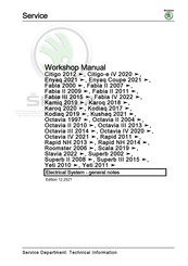
Skoda Fabia III 2015 Workshop Manual (211 pages)
Brand:
Skoda
| Category:
Air Conditioner
| Size: 4 MB
Table of Contents
Service
3
Table of Contents
3
Technical Data
5
General Notes on the Air Conditioning System
5
Important Instructions
5
Further Documentation and Information Means
6
Principles of the Air-Conditioning Technology
6
Advantages of the Air Conditioning System - Comfort
8
Operation of the Air Conditioning System
8
Refrigerant R134A
9
Vapour Pressure Table for Refrigerant R134A
10
Properties of Refrigerant R134A
11
Evidence of Leaks
12
Refrigerant Oil
13
General Occupational Safety
13
Using Pressure Tank
15
Safety Precautions When Working with Extraction and Filling Systems
16
Safety Measures When Working on Vehicles with Air Conditioning System and When Using
17
Basics for Working on the Refrigerant Circuit
18
General Instructions for Refrigerant Circuit
21
Extractor, Filler and Measurement Valves for Quick Couplings of the AC Service Station on the
26
Pressures and Temperatures in the Refrigerant Circuit and Its Arrangement
28
Switch and Sender on the Refrigerant Circuit
32
Electrical Components Which Are Not Fitted on the Refrigerant Circuit
33
The Inspection and Measurement Work Can be Performed Using the Pressure Gauge
34
Air Conditioning Service and Recycling Equipment
35
Repair and Maintenance Instructions for Refrigerant Circuit
35
Legal Texts and Legal Regulations
37
Laws and Regulations
37
Verification Procedure of Refrigerant
38
Refrigerant Circuit
39
Important Repair Instructions for Air Conditioning Systems
39
Working with the A/C Service Station
40
Important Instructions for Working with the A/C Service Station
41
Connecting the A/C Service Station to the Refrigerant Circuit for Measuring and Testing
42
Empty the Refrigerant Circuit with the A/C Service Station
42
Important Instructions for Working with the A/C Service Station
42
Evacuate the Refrigerant Circuit with the A/C Service Sta- Tion
43
Evacuate the Refrigerant Circuit with the A/C Service Station
43
Fill Refrigerant into the Reservoir (Filling Cylinder or Reservoir Bottle) of the A/C Service Station
44
Fill the Refrigerant Circuit with the A/C Service Station
44
Operate the Air Conditioning System after Filling
44
Draining the A/C Service Station
45
Leak Detection on the Refrigerant Circuit
46
Looking for Leaks in the Refrigerant Circuit - Important Instructions
46
Leak Detection on the Refrigerant Circuit with Compressed Air or Nitrogen
47
Detecting Leaks on the Refrigerant Circuit with the Leak Detector VAG1796
49
Detecting Leaks on the Refrigerant Circuit with the Leak Detector VAS 6196 or VAS 6201A
49
Cleaning the Refrigerant Circuit with Compressed Air and Nitrogen
56
Removing Contaminants from the Refrigerant Circuit
56
Cleaning Refrigerant Circuit with Refrigerant R134A (Flush)
58
Principle Circuit Diagrams for Different Rinsing Cycles
62
Adapter for Setting up the Rinsing Cycles
65
Complaints
70
Possible Complaints
70
Temperature Test of Cooling Capacity
71
Odour from the Heating and Air Conditioning Unit
72
Check the Pressure in the Refrigerant Circuit (with the A/C Service Station)
75
Test Requirements before the Pressure Test
75
Check Pressures
76
Continuation of the Test Depending on the Arrangement of the Refrigerant Circuit
78
Pressure Test for Vehicles with Throttle and Catch Pan (with AC Compressor Regulated from the Inside)
78
Pressure Test for Vehicles with Expansion Valve and Fluid Reservoir (with AC Compressor Regulated from the Inside)
82
Replace Components of the Refrigerant Circuit
95
Replace Parts on the Refrigerant Circuit - General Instructions
95
Components of the Refrigerant Circuit Leaking or Damaged - the Refrigerant Circuit Is Absolutely Empty
96
Components of the Refrigerant Circuit Leaking or Damaged - Refrigerant Is Still in the Refrigerant Circuit
97
Replace AC Compressor
97
Replace Catch Pan and Throttle/Fluid Reservoir
98
Tools and Materials, Which Are Avail- Able from the Importer
100
Tools and Materials, Which Are Available from the Importer
100
A/C Service Station
101
Flushing Device for the Refrigerant Circuits 6336/1 or Fol- Low-Up Models (Manufacturer Waeco)
102
Flushing Device for the Refrigerant Circuits 6336/1 or Follow-Up Models (Manufacturer Waeco)
102
Flushing Device for the Refrigerant Circuits 6337/1 or Fol- Low-Up Models (Manufacturer Behr)
102
Flushing Device for the Refrigerant Circuits 6337/1 or Follow-Up Models (Manufacturer Behr)
102
Leak Detection System VAS 6196
102
Leak Detector V.A.G 1796
102
Adapter Case of Motor Car Set VAS 6338/1
103
Case of Release Tools VAS 6127/3
103
Leak Detection System VAS 6201A
103
Socket Insert T10364
103
Setting up Tools and Materials Which Are Available from a Dealer
104
Tools and Materials, Which Are Commercially Available
104
Bottle Connecting Piece for Pressure Bottle
105
Filling Hoses
105
Valve Caps with Replacement Gaskets
105
A/C Service Station
106
Pressure Gauge with Pressure Reducer for Nitrogen
106
Quick-Coupling Adapter for Service Connections
106
Tools, Which You Make Yourself
106
Service
109
Heating
111
Summaries of Components, Disassembling and Assembling the Heater Unit
111
Summary of Components - Interior
111
Assembly Overview - Heater Unit
113
Disassembling and Assembling the Heater Unit
114
Summary of Components: Heat Exchanger, Heating Element for Air Auxiliary Heating Z35
116
Dash Panel Vent and Air Guide Ducts, Ventilation
117
Removing and Installing the Centre Dash Panel Vent
117
Remove and Install Footwell Vent
118
Removing and Installing the Right/Left Side Vent
118
Remove and Install the Forced Ventilation Frame for Passenger Compartment, Check
119
Heater Control
121
Removing and Installing Heater Control
121
Plug Connections at the Heater Control
122
Removing and Installing Flex Shafts
122
Components on the Heater Unit
124
Components on the Heater Unit
125
Removing and Installing Control Motor of Fresh Air Flap and Re-Circulating Air Flap V154
125
Removing and Installing Dust Pollen Filter
127
Removing and Installing the Control Motor for Air Distribution Flaps
128
Removing and Installing the Control Unit for Temperature Flap
129
Removing and Installing Fresh Air Blower V2
130
Removing and Installing Series Resistor for Fresh Air Blower N24
131
Removing and Installing the Heating Unit from the Vehicle
132
Air Conditioning System
134
Notes Regarding the Odours Coming from the Heating and Air Conditioning Unit
135
Description of the Air Conditioning System
136
Operation of the Air Conditioning System
136
Structure of the Refrigerant Circuit
136
Parts of the Refrigerant Circuit
138
Extractor, Filler and Measurement Valves for Quick Couplings of the AC Service Station on the
140
Parts of the Protection and Control of the Refrigerant Circuit
142
Refrigerant Circuit
142
Properties of Refrigerant R 134A and of the Refrigerant Oil
145
Refrigerant Oil
146
Refrigerant R134A
146
Air Conditioning System - Engine Com- Partment
148
Air Conditioning System - Engine Compartment
149
Components of the Air Conditioning System in the Engine Compartment - Summary of Components- Vehicles from MY 2011
152
Removing and Installing the Refrigerant Lines of the Con- Denser
153
Removing and Installing the Refrigerant Lines of the Condenser
153
Removing and Installing the Refrigerant Lines from the AC Compressor
155
Removing and Installing the Refrigerant Lines on the Ex- Pansion Valve
156
Removing and Installing the Refrigerant Lines on the Expansion Valve
156
Check Valve for Condensation Water Drain
157
Removing and Installing the AC Compressor from Holder
157
Removing and Installing Ambient Temperature Sensor G17
158
Components of the Air Conditioning System - Engine Compartment
159
Removing and Installing, Inspecting High Pressure Sender G65
159
Removing and Installing the Expansion Valve
160
Inspecting the Pressure Relief Valve on the AC Compressor
161
Removing and Installing AC Compressor
161
Reasons for Rinsing the Refrigerant Circuit
163
Running-In Instructions of the AC Compressor
163
Removing and Installing the Condenser
164
Replace Dessicator Cartridge
165
Repairing Air Conditioning System Magnetic Coupling N25
168
Quick Couplings for Refrigerant Lines
172
Separating Quick Couplings for Refrigerant Lines
172
Removing and Installing the Heating and Air Conditioning Unit from the Vehicle
176
Dash Panel Vent and Air Guide Ducts, Ventilation
179
Climatic, Air Conditioning System with Manual Control
180
10. Climatic, Air Conditioning System with Manual Control
181
Summary of Components - Heating and Air Conditioning Unit
183
Dismantling and Assembling Heater and Air Conditioning Unit
185
Expansion Valve - Summary of Components
187
Removing and Installing Evaporator
187
Control for Heating and Air Conditioning System
189
Removing and Installing Flex Shaft for Positioning Unit of Air Distribution Flaps
191
Removing and Installing Control Motor of Fresh Air Flap and Re-Circulating Air Flap V154
192
Removing and Installing the Control Motor of Temperature Flap V68
192
Climatronic - Air Conditioner with Automatic Regulation)
195
Summary of Components - Interior
195
Summary of Components of Heating and Air Conditioning Unit
198
Dismantling and Assembling Heater and Air Conditioning Unit
200
Function of the Control and Display Unit for Front Air Con- Ditioning System E87 with Climatronic Control Unit J255
202
Function of the Control and Display Unit for Front Air Conditioning System E87 with Climatronic Control Unit J255
202
Removing and Installing Fresh Air Blower Control Unit J126
206
Removing and Installing Sunlight Penetration Photosensor G107
206
Removing and Installing the Control Motor of Air Flow Flap V71
207
Removing and Installing the Control Motor of Central Flap V70
208
Removing and Installing Defroster Flap Control Motor V107
209
Removing and Installing Defroster Flap Control Motor V107 and Temperature Flap Control Motor V68
209
Advertisement
Skoda Fabia III 2015 Workshop Manual (223 pages)
Brand:
Skoda
| Category:
Automobile
| Size: 8 MB
Table of Contents
Table of Contents
3
Technical Data
7
Safety Instructions
7
Safety Precautions When Working on Vehicles with a Start/Stop System
7
Safety Precautions During Road Tests in Which Testing and Measuring Equipment Is Used
7
Safety Precautions When Working on the Assembly Carrier
8
Repair Instructions
9
Leaks on Shock Absorbers
9
Noises on Shock Absorbers
9
Inspecting the Removed Shock Absorber
10
Steering Gear
11
Gaskets, Seals
11
Screws, Nuts
11
Electrical Components
11
Raise Wheel Bearing in Unladen State on Vehicles with Coil Springs
11
Assessing Accident Vehicles
14
Checklist for Assessing the Chassis of Accident Vehicles
14
Technical Data
16
Steering
16
Front Suspension
17
Front Axle
17
Overview - Front Axle
17
Assembly Carrier
18
Summary of Components- Assembly Carrier
18
Removing and Installing Assembly Carrier Without Steering Gear
20
Removing and Installing the Anti-Roll Bar
24
Replace Assembly Bracket
30
Removing and Installing Coupling Rod
30
Fixing the Assembly Carrier
31
Lower Assembly Carrier
38
Suspension Strut
45
Summary of Components - Suspension Strut
45
Removing and Installing the Suspension Strut
46
Repairing Suspension Strut
51
Bottom Track Control Arm, Steering Joint
53
Summary of Components - Lower Track Control Arm. Steering Joint
53
Removing and Installing the Lower Track Control Arm
54
Inspecting the Steering Joint
57
Removing and Installing the Steering Joint
57
Replacing the Rubber-Metal Bearing for Lower Track Control Arm
61
The Wheel Bearing
63
Summary of Components - Wheel Bearing
63
Removing and Installing Wheel Bearing Housing
64
Removing and Installing Wheel-Bearing Unit
69
Drive Shaft
75
Summary of Components - Drive Shaft
75
Removing and Installing Drive Shaft
90
Removing and Installing Nuts for Drive Shaft
113
Removing and Installing Heat Shield for Drive Shaft
116
Disassembling and Assembling Drive Shaft
116
Inspecting Outer CV Joint
124
Inspecting Inner CV Joint
125
Clamp the Clamp on the Tripod Joint and Outer Joint
127
Rear Suspension
129
Rear Axle
129
Overview - Rear Axle
129
Removing and Installing Rear Axle
130
Axle Body
136
Summary of Components- Axle Beam
136
Rubber-Metal Bearing for Axle Beam
142
Suspension Strut/Shock Absorber, Spring
154
Summary of Components - Suspension Strut/Shock Absorber, Spring
154
Removing and Installing Shock Absorber
154
Removing and Installing Spring
157
Wheel Bearing, Longitudinal Swing Arm
159
Summary of Components - Wheel Bearing
159
Removing and Installing Wheel-Bearing Unit
162
Wheels, Tyres, Vehicle Geometry
169
Wheels, Tyres
169
Replacing a Wheel
169
Tightening Torque of the Wheel Screws
172
Tyre Sealant
172
Disposing of Tyre Sealant
172
Carry out Axle Alignment
174
Notes on Axle Alignment
174
Test Conditions
175
Measurement Preliminaries
176
Nominal Values for the Axle Alignment
178
Checking the Transversal Inclination of the Vehicle
180
The Necessity to Perform an Axle Alignment
180
Explanations Concerning PR Numbers
181
Adjusting the Camber on the Front Axle
181
Adjust the Camber on the Rear Axle
184
Adjusting the Track on the Rear Axle
184
Adjusting the Track on the Front Axle
184
Check the Maximum Steering Angle
186
Adaptive GRA
187
Calibrate Adaptive GRA
187
Check Position of Steering Wheel, Align if Necessary
191
Steering
193
Steering Wheel
193
Steering Wheel - Summary of Components
193
Removing and Installing the Steering Wheel
194
Steering Column
195
Summary of Components - Steering Column
195
Observe Handling and Transportation of the Steering Column
198
Removing and Installing Steering Column
199
Installing and Removing Intermediate Shaft of Steering
208
Removing and Installing the ELV J764
209
Steering Gear
210
Summary of Components - Steering Gear
210
Removing and Installing Steering Gear
210
Removing and Installing Track Rod
213
Removing and Installing Track Rod Ends
217
Repairing Steering Box
220
Adjusting Steering Box
221
Sender
223
Removing and Installing Steering Angle Sender G85
223
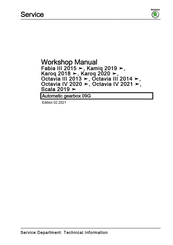
Skoda Fabia III 2015 Workshop Manual (235 pages)
Brand:
Skoda
| Category:
Automobile
| Size: 4 MB
Table of Contents
Table of Contents
3
Technical Data
5
Safety Instructions
5
Safety Precautions for Working on Vehicles with Start-Stop System
5
Safety Precautions During Road Tests in Which Testing and Measuring Equipment Is Used
5
Safety Measures During Towing/Tow-Starting
5
General Safety Instructions
5
Identification
7
Gearbox Identification
7
Torque Converter Identification
7
Repair Instructions
9
Rules of Cleanliness
9
General Points
9
General Repair Instructions
11
Contact Corrosion
14
Seals and Sealing Rings
14
Screws, Nuts
14
Technical Data
16
Filling Capacity
16
Allocation Gearbox - Engine
16
Torque Converter
18
Summary of Components - Torque Converter
18
Removing and Installing Torque Converter
18
Draining the Torque Converter
20
Checking the Torque Converter
20
Removing and Installing Gasket Ring for Torque Converter
21
Controls, Housing
23
ATF Circuit
23
Summary of Components - ATF Circuit
23
Removing and Installing ATF Radiator
23
Atf
27
Inspecting ATF Level
27
Draining and Filling ATF
32
Removing and Installing the Gearbox
36
Tightening Torques for Gearbox
36
Removing the Gearbox
41
Installing the Gearbox
105
Transporting the Gearbox
118
Attachment at Engine and Gearbox Mount
119
Shift Mechanism
121
Fitting Position Overview - Switching Operation
121
Summary of Components - Gearshift Mechanism
123
Inspecting the Gearshift Mechanism
131
Emergency Release out of P Position
135
Removing and Installing Selector Mechanism
143
Removing and Installing Selector Lever Handle
167
Installing the Lock Button at the Selector Lever Handle
184
Removing and Installing the Selector Lever Control Cable
186
Inspecting and Adjusting the Selector Lever Control Cable
191
Removing and Installing the Multi-Function Switch
195
Setting the Multi-Function Switch
202
Replacing Cable Adjusting Element
205
Replacing the Sealing Ring for the Gearshift Shaft
208
Gears, Control
210
Slide Valve Body
210
Summary of Components - Slide Valve Body
210
Remove and Install Wiring Harness of Encoders and Solenoid Valves
213
Removing and Installing the Slide Valve Body
216
Removing and Installing Oil Pan
219
Removing and Installing the Oil Filter
221
Removing and Installing the Gearbox Input Rpm Sender G182 and the Transmitter for the Gearbox Output Speed Sender G195
222
Final Drive - Differential
224
Sealing Rings
224
Replacing Left Sealing Ring
224
Replacing Right Sealing Ring
226
Gearbox Control System
230
Removing and Installing Gearbox Control Unit
230
Advertisement
Skoda Fabia III 2015 Workshop Manual (117 pages)
Brand:
Skoda
| Category:
Automobile
| Size: 2 MB
Table of Contents
Table of Contents
3
Starter, Current Supply, CCS
5
Battery
5
Basics about Batteries
5
Battery Types
5
Warning Instructions and Safety Precautions When Working on the Battery
8
Working on the Airbag System
9
Screwed Connections of Battery Poles
10
Checking Battery
11
Check Battery with a Magic Eye
11
Checking Fleece Battery (AGM)
14
Visual Inspection of the Battery
14
Notes on Battery Replacement and Battery Degassing
15
Battery Tester with Printer VAS 6161
16
Battery Tester with Printer VAS 5097 a
21
Check Current Drain When Charging
22
Load Voltage Measurement - Demonstration Vehicles and Stock Vehicles
23
Charge Battery
24
Charging Battery
24
Severely Discharged Batteries
26
Cruise Control System (CCS)
28
General Description
28
Activate/Deactivate Cruise Control System
28
Windscreen Wash/Wipe System
29
Repairing Washer Fluid Level Pipes
29
Repair Solution for Plain Ended Pipe
29
Repair Solution for Corrugated Pipe
30
Washer Fluid Lines
34
Connections of Washer Fluid Level Pipes
34
Joint-Free Wiper Blades
36
Distinguishing Features of Joint-Free Wiper Blades
36
Lights, Bulbs, Switches - Exterior
37
Gas Discharge Lamps
37
Use and Safety Instructions for Gas Discharge Lamps
37
LED Headlights
39
Application and Safety Instructions for LED Headlights
39
Lights, Bulbs, Switches - Interior
40
Power Sockets, Cigarette Lighter
40
Removing and Installing the 12 V Power Socket/Cigarette Lighter in the Centre Console
40
Protected by Copyright. Copying for Private or Commercial Purposes, in Part or in Whole, Is Not Permitted
40
Wiring
43
Vehicle Diagnosis, Testing and Information Systems
43
Safety Instructions
43
Connect Vehicle Diagnosis, Measurement and Information System VAS 505X
43
Wiring Harness Repair
45
General Instructions for the Repair on the Vehicle Electrics
45
General Instructions for Wiring Harness and Plug Repair
46
Tool Descriptions
47
Repair of Airbag and Belt Tensioner Cables
52
Repair of CAN Bus Lines
54
Crimp New Contacts
55
Repair of 0.13 Mm2/ 0.35 Mm2/ 0.5 Mm2 Cable
58
Repair a 10 Mm2- or 16 Mm2 Cable with an Individual Joint Butt Splice Connector
63
Line Break with Single Repair Point
70
Line Break with Two Repair Points
73
Repairing Aerial Cables
76
Repairing Socket Housings and Connectors
87
Notes on Repairing Socket Housings and Connectors
87
Repairing Contacts in Socket Housings
87
Assembly of Single Cable Seals
89
Unlocking and Disassembling Socket Housings
92
Notes on Unlocking and Disassembling Socket Housings
92
Secondary Lock
92
Primary Lock
93
Repairing Optical Fibres
100
General Points
100
Preparing Optical Fibres
100
Removing and Installing Optical Fibre in the Housing
106
Contact Surface Cleaning Set VAS 6410
108
Use Contact Surface Cleaning Set VAS 6410
108
Repairing the Cable Eyes
108
Repairing Screwed Connections
110
Cleaning the Battery Pole Terminals and Battery Poles
112
Preserving
113
Replace the Lambda Probe
115
Replace the LSF Lambda Probe (4-Pole)
115
Replace the LSU Lambda Probe (6-Pole)
116
Protective Pipe Variants of the Unit Lambda Probes
117
Advertisement
Related Products
Skoda Octavia III 2013
Skoda Octavia III 2014
Skoda III 2013
Skoda III 2014
Skoda Octavia II 2004
Skoda Octavia II 2010
Skoda Fabia II 2007
Skoda Fabia II 2011
Skoda Superb II 2008
Skoda Octavia II 2006
Skoda Categories
Automobile
Automobile Accessories
Car Receiver
Car Navigation system
Car Video System
More Skoda Manuals
Login
Sign In
OR
Sign in with Facebook
Sign in with Google
Upload manual
Upload from disk
Upload from URL