Sign In
Upload
Manuals
Brands
Scanlab Manuals
Recording Equipment
RTC 5 PC Interface Board
User Manuals: Scanlab RTC 5 PC Interface Board Control
Manuals and User Guides for Scanlab RTC 5 PC Interface Board Control. We have
1
Scanlab RTC 5 PC Interface Board Control manual available for free PDF download: Installation And Operation Manual
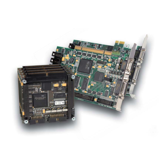
Scanlab RTC 5 PC Interface Board Installation And Operation Manual (622 pages)
Brand:
Scanlab
| Category:
Recording Equipment
| Size: 4 MB
Table of Contents
Table of Contents
3
Introduction
22
Manufacturer
22
Identification
22
Unpacking Instructions and Typical Package Contents
23
Delivered Software
23
Product Overview
25
Intended Use
25
System Requirements
26
Hardware
26
Software
26
Optional Functionality
27
Jumper Settings and Type Identification
28
Jumper JP1: Selecting the Output Signal Level at the EXTENSION 1 Connector
28
Jumper 2-8: Configuring Pin15 and Pin17 at the EXTENSION 2 Connector
28
Type Identification
29
Optional Accessories
29
XY2-100 Converter
29
Data Cables
29
Laser Adapter
29
PCI Slot Covers
29
ADC Add-On Board
30
Supplementary Software
30
Notes for RTC ® 4 Users
30
Hardware Changes
30
Scan System Control
30
Laser Control
31
EXTENSION 1 Connector
31
EXTENSION 2 Connector
31
MARKING on the FLY Connector
31
Other Connectors
31
Porting RTC ® 4 Programs to the RTC ® 5
32
Changed Initialization
32
Command Changes
32
Increased Parameter Resolution
33
Changed Timing Behavior
34
New and Changed Functionality
34
Interface to the PC
34
Scan System Control
34
Laser Control
35
Interfaces for Peripheral Equipment
36
General Programming
36
Laser Marking
36
Special Functions
37
Safety During Installation and Operation
38
Steps for Safe Operation
38
Laser Safety
38
Layout and Interfaces
39
Connectors and Jumper Positions
39
Interface to PC
40
Master/Slave Synchronization
40
Interfaces to Scan System
41
Scan Head Connectors and Transfer Protocol
41
Primary Scan Head Connector
41
Secondary Scan Head Connector (Optionally Activated)
41
XY2-100 Converter (Optional)
42
Data Cable (Optional)
44
Interfaces for the Laser and Peripheral Equipment
46
Laser Connector
46
Laser Signals
46
External Control Signals
46
BUSY Status
46
Digital Input and Output
46
Analog Output Ports
47
I/O Circuits
47
Laser Adapter (Optional)
48
EXTENSION 1 Connector
49
Configuring the Output Signal Level
49
16-Bit Digital Input and Output
49
Synchronization of Data Transmission
49
BUSY Status
49
EXTENSION 2 Connector
50
Jumper Setting
50
Laser Signals
50
8-Bit Digital Output Port
50
MARKING on the FLY Connector
51
Encoder Inputs
51
External Control Signals
51
Analog Output Port
51
BUSY Status
51
Slot Cover (Optional)
51
RS232 Interface
51
Mcbsp and I2C Interface
52
I2C Interface
52
Mcbsp Interface
52
Stepper Motor Control
53
Analog Inputs
54
Installation and Start-Up
56
Jumper Settings
56
Installing the Hardware
56
Installing the Drivers
57
Software Driver Upgrade
57
Installing the RTC ® 5 Software
58
Safe Start-Up and Shutdown Sequences
58
Start-Up and Functionality Test
59
User Applications and Demo Software
59
Upgrading RTC ® 5 Boards
60
Developing User Applications
61
RTC ® 5 Software Basics
61
Controlling Scan Systems and Lasers - an Introductory Example
61
List Commands and Control Commands
61
Initialization and Program Start-Up
62
DLL Call
62
Importing Commands
62
Pascal
62
Initializing the DLL and Board Management
64
Start of Operation
65
RTC ® 5 Initialization
65
RTC ® 5 Configuration
65
Scan System Initialization
65
Laser Control Initialization
66
Loading and Executing Lists
66
Example Code
67
List Memory
69
Lists and the Protected Buffer Area
69
Lists
69
Protected Buffer Area
69
Configuring the List Memory
70
List Handling
71
Loading Lists
71
Unconditional" Loading
71
Loading with Protection
72
Terminating Lists
72
List Status
72
List Execution Status
73
Starting and Stopping Lists
74
Interrupting Lists for Synchronization of Processing
74
Automatic List Changing
75
One-Time List Change
75
Alternating List Changes
75
Structured Programming
76
Subroutines
76
Non-Indexed Subroutines
76
Indexed Subroutines
76
Calling Subroutines
77
Subsequent Protection and Conversion of Non-Indexed Subroutines
78
Deprotecting Subroutines
79
Index Management and Defragmentation
79
Character Sets and Text Strings
80
Defining Indexed Character Sets
80
Calling Indexed Characters
80
Defining Indexed Text Strings for Times, Dates and Serial Numbers
80
Calling Indexed Text Strings
81
Management of Indexed Characters and Text Strings
81
Jumps
81
Circular Queue Mode
82
Loops
82
Using Multiple RTC ® 5 Boards in One Computer
83
Multi-Board Programming
83
Sequential Programming
83
Master/Slave Operation
84
Initialization
84
Clock Phase Synchronization
84
Matching of Short-Command Counts (as of Version DLL 523, out 524)
84
Synchronous Starts and Stops
84
Usage by Multiple Applications
85
Board Acquisition by an Application
86
Error Handling
87
Download Verification
88
Checking for Overruns
89
Example Code
90
Miscellaneous
92
Free Variables
92
Basic Functions for Scan Head and Laser Control
93
Marking Points, Lines and Arcs
93
Marking with Vector and Arc Commands
93
Jump Commands
93
Mark Commands
94
Arc Commands
94
Ellipse Commands
94
Para Commands
95
Microsteps
96
Marking Points
96
Example Code
97
Delay Settings for Synchronizing Scan Head and Laser Control
99
Laser Delays
99
Laseron Delay
99
Laseroff Delay
99
Scanner Delays
100
Jump Delay
100
Variable Jump Delay
101
Mark Delay
102
Polygon Delay
103
Variable Polygon Delay
104
Customizing the Variable Polygon Delay
106
Notes on Optimizing the Delays
107
Recommended Sequence
107
Automatic Delay Adjustments
107
Optimizing the Delays
110
Sky Writing
113
Mode 1
113
Mode 2
113
Mode 3
114
Synchronization
115
Notes
117
Scan Head Control
118
Reference System
118
Image Field Size and Calibration
119
Typical Image Field
119
RTC ® 4 Compatibility Mode
120
Virtual Image Field
120
Image Field Correction and Correction Tables
120
Field Distortion
120
Field Correction Algorithm
121
Activating Image Field Correction
122
And 3D Correction Files
122
Loading Correction Tables
122
Assigning Loaded Correction Tables
122
1To1 Correction Tables
124
Inverse Tables
124
Correction File Header
124
Converting Correction Files
125
Output Values to the Scan System
126
Calculations
126
Value Ranges
126
Clock Overruns
126
Status Monitoring and Diagnostics
127
Status Information Returned from the Scan System
127
Laser Control
128
Enabling, Activating and Switching Laser Control Signals
128
Laser Active" Signals
129
Laser Standby" Signals
129
Scan-System-Error-Induced Laser-Signal Auto-Suppression
130
Galvanometer Position Exceedance-Induced Laser-Signal Auto-Suppression
130
Configuring the Laser Connector (LASER)
130
CO Mode
131
YAG Modes
132
Q-Switch Signal
132
Firstpulsekiller Signal
133
Differences between the YAG Modes
133
Lamp Current (Laser Power)
133
Softstart Mode
135
Laser Mode 4
136
Laser Mode 6
137
Pulse Picking Laser Mode
138
Automatic Laser Control
140
Position-Dependent Laser Control
141
Speed-Dependent Laser Control
146
Vector-Defined Laser Control
147
Encoder-Speed-Dependent Laser Control
148
Output Synchronization
149
Marking Dates, Times and Serial Numbers
150
Marking the Date and Time
150
Marking Serial Numbers
150
Notes
150
Advanced Functions for Scan Head and Laser Control
152
Idrive ® Functions
152
Transfer Protocol
152
Configuring Status Return Behavior
153
Selecting Data Signals
153
Querying Data
153
Position Monitoring
154
Configuring Dynamics Settings (Tuning)
155
Jump Mode
156
Functional Principle
156
Requirements and Activation
157
Jump-Length-Dependent Jump Delays
157
Experimental Determination of Jump Delay Values
158
Notes on Loading Determined Jump Delay Values
158
Automatic Determination of the Jump Delay Table
159
Configuring the Posacknowledge Threshold Value
160
Configuring the Effective Calibration
160
Configuring the Start Behavior
160
Fault Diagnosis and Functional Test
161
Coordinate Transformations
161
Online Positioning
165
Configuring Online Positioning
165
Notes
166
Wobbel Mode
167
Wobbel Shapes - Important Notes on Choosing Appropriate Parameter Values
168
Classic" Wobbel Shapes
168
Freely Definable Wobbel Shapes
169
Using Several Different Correction Tables
170
Configuration with Two 2D Scan Systems
170
Using Several Correction Tables with a Single Scan System
170
Controlling a 3-Axis Scan System (Optional)
171
Intended Use
171
Connection and Initialization
171
Marking Commands
172
Adjustment
174
Checking the Z-Axis Calibration
174
Test for 3-Axis Scan Systems with F-Theta Objective
175
Enhanced 3D Correction
176
Processing-On-The-Fly (Optional)
177
Intended Use and Initialization
177
Overview
178
Compensation of Linear Movements
179
Correction Via Encoder Counter(S)
179
Correction Via Mcbsp Interface
180
Correction Via Mcbsp Interface with Additional Mcbsp Input
181
Correction Via Mcbsp Interface with Enhanced Mcbsp Input
181
Compensation of Rotary Movements
181
Correction Via Encoder Counter
181
Correction Via Mcbsp Interface
182
Correction Via Mcbsp Interface with Additional Mcbsp Input
183
Compensation of 2D Motions
184
Encoder Compensation for XY Stages
184
Coordinate Transformations in the Virtual Image Field
185
Deactivating Processing-On-The-Fly Corrections
186
Virtual Image Field
187
Synchronization of Processing-On-The-Fly Applications
188
Encoder Resets
189
Monitoring Processing-On-The-Fly Corrections
190
Customer-Defined Monitoring Area and Conditional Command Execution (as of Version DLL 525, out 527)
190
Tracking Error Compensation of Encoder Values for Processing-On-The-Fly Applications
191
Scanning Raster Images (Bitmaps)
192
Principle of Operation
192
Software Commands
192
Laser Control
193
Timing
194
Microvector Commands
197
Timed Vector and Arc Commands
198
Automatic Self-Calibration
199
Using for Drift Compensation
199
How It Works
199
Determining Reference Values
200
Calibration During an Application
201
Automatic Self-Calibration
201
Customer-Specific Calibration
201
Supplemental Information about Calibration
202
Programming Peripheral Interfaces
203
Signal Output
203
16-Bit Digital Output Port
203
8-Bit Digital Output Port
204
12-Bit Analog Output Ports
204
Stepper Motor Control
205
Output Signals
205
Reference Movements and Position Initialization
205
Set-Position Movements
206
Querying Signals and Status Values
206
Terminating Infinite Movements
206
RS232 Interface
207
Mcbsp Interface
207
Signal Input
207
16-Bit Digital Input
207
RS232 Interface
208
Mcbsp Interface
208
Control Via External Signals
209
Starting and Stopping Lists Via External Control Signals and Master/Slave Synchronization
209
External List Stop
209
External List Start
210
External List Start with Track Delay
210
Regular (Periodic) External List Starts
212
Conditional Command Execution
213
Programming Examples
214
Synchronization Via Encoder Signals
215
Intended Use
215
Inputs for External Encoder Signals
215
Encoder Simulation
216
Synchronization and Online Positioning Via Mcbsp Signals
216
Commands and Functions
217
Overview
217
Nomenclature
217
Multi-Board Commands
217
Normal, Short and Variable List Commands and List Multi-Commands
217
Undelayed and Delayed Short List Commands (as of Version out 515)
218
List Multi-Commands
218
Compatibility
219
Version Information
219
Optional Functions
219
Control Commands
220
List Commands
223
Data Types
226
RTC ® 5 Command Set
227
Acquire_Rtc
227
Activate_Fly_2D
228
Activate_Fly_Xy
229
Apply_Mcbsp
230
Apply_Mcbsp_List
231
Arc_Abs
233
Arc_Abs_3D
233
Arc_Rel_3D
233
Arc_Rel
234
Auto_Cal
238
Auto_Change
238
Auto_Change_Pos
239
Bounce_Supp
240
Clear_Fly_Overflow
240
Clear_Io_Cond_List
241
Config_Laser_Signals
242
Config_Laser_Signals_List
242
Config_List
243
Control_Command
244
Copy_Dst_Src
254
Disable_Laser
255
Enable_Laser
255
Execute_At_Pointer
256
Execute_List
256
Execute_List_1
256
Execute_List_2
256
Execute_List_Pos
257
Fly_Return
258
Fly_Return_Z
259
Free_Rtc5_Dll
259
Get_Auto_Cal
260
Get_Char_Pointer
260
Get_Config_List
261
Get_Counts
261
Get_Dll_Version
261
Get_Encoder
262
Get_Error
263
Get_Fly_2D_Offset
264
Advertisement
Advertisement
Related Products
Scanlab RTC 4
Scanlab RTC6 PCIe Board
Scanlab RTC 5 PC/104-Plus Board
Scanlab RTC 5 PCIe/104 Board
Scanlab RTC 5-Express Board
Scanlab Categories
Recording Equipment
Computer Hardware
Test Equipment
More Scanlab Manuals
Login
Sign In
OR
Sign in with Facebook
Sign in with Google
Upload manual
Upload from disk
Upload from URL