Sign In
Upload
Manuals
Brands
Scanlab Manuals
Recording Equipment
RTC 4
Scanlab RTC 4 Manuals
Manuals and User Guides for Scanlab RTC 4. We have
1
Scanlab RTC 4 manual available for free PDF download: Installation And Operation Manual
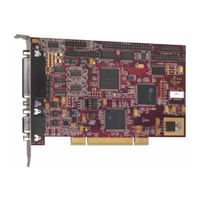
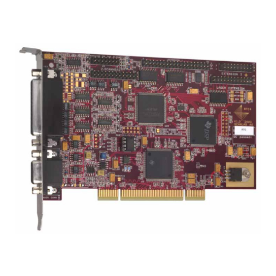
Scanlab RTC 4 Installation And Operation Manual (136 pages)
Interface Board for Real Time Control of Scan Heads and Lasers
Brand:
Scanlab
| Category:
Recording Equipment
| Size: 2 MB
Table of Contents
Table of Contents
3
1 Delivered Product
6
Package Contents
6
Manufacturer
6
About this Operating Manual
6
2 Product Overview
7
Intended Use
7
System Requirements
7
Board Dimensions and Layout
8
Notes for RTC ® 3 Users
10
Hardware Changes
10
Installation Tips
10
Changes in the Command Set
10
3 Safety During Installation and Operation
11
Steps for Safe Operation
11
Laser Safety
11
4 Principle of Operation
12
Software Concept
12
List Commands and Control Commands
12
List Handling
13
Automatic List Handling
13
External Control Inputs
13
Synchronization of Processing
14
Scan Head and Laser Control
15
Vector Commands
15
Arc Commands
15
Microsteps
15
Delays
16
Laser Delays
16
Scanner Delays
17
Notes on Optimizing the Delays
24
Image Field Size
29
Image Field Correction
30
Laser Control
32
CO 2 Mode
33
YAG Modes
34
Softstart Mode
35
Laser Mode 4
37
Status Monitoring and Diagnostics
38
Intelliscan ® - Additional Functions
38
The XY2-100 Enhanced Protocol
38
Selecting Data Signals
38
Querying Data
39
5 Advanced Programming
40
Coordinate Transformations
40
Wobbel Function
41
Using Two Different Correction Files
42
Double Scan Head Configuration
42
Using Two Correction Files in a Single Scan Head System
42
Using Multiple RTC ® 4 Boards in One Computer
43
Circular Queue Mode
44
Structured Programming
45
Input Pointer
45
List Jumps
45
Conditional List Jumps
45
Output Pointer
45
Programming Examples
46
Scanning Raster Images (Bitmaps)
47
Timed Jump and Mark Commands
50
Automatic Self-Calibration
51
6 Electrical Connections
52
Laser Connector
52
Analog Output Ports
52
Laser Signals
52
External Control Signals
52
Laser Extension Connector
53
8-Bit Digital Output Port
53
Laser Signals
53
Primary Scan Head Connector
54
Control Signals
54
Status Signals
54
Secondary Scan Head Connector (Optional)
54
Data Cable
55
Optical Data Interface (Optional)
56
EXTENSION 1 Connector
56
16-Bit Digital Input and Output
56
BUSY Status
56
7 Options
57
8 Installation and Start-Up
58
Jumper Settings Overview
58
Changing the Jumper Settings
59
TTL Laser Signal Level
59
Laser / Analog Output Ports (9-Pin Laser Connector)
59
Digital Output Port (Laser Extension Connector)
60
Installing the Hardware
60
Installing the Drivers
61
Start-Up and Functionality Test
61
9 Software
62
Installing the Software
62
DLL Calling Convention
62
Pascal
62
Basic
62
Initializing the RTC ® 4
63
Demo Programs
64
10 Commands and Functions
69
Overview
69
Control Commands
70
List Commands
71
Data Types
72
Command Set
73
Supported and Unsupported RTC ® 2 Commands
125
Troubleshooting
128
12 Customer Service
129
Servicing and Repairs
129
Warranty
129
Contacting SCANLAB
129
Product Disposal
129
13 Technical Specifications
130
Advertisement
Advertisement
Related Products
Scanlab RTC 5 PC Interface Board
Scanlab RTC6 PCIe Board
Scanlab RTC 5 PC/104-Plus Board
Scanlab RTC 5 PCIe/104 Board
Scanlab RTC 5-Express Board
Scanlab Categories
Recording Equipment
Computer Hardware
Test Equipment
More Scanlab Manuals
Login
Sign In
OR
Sign in with Facebook
Sign in with Google
Upload manual
Upload from disk
Upload from URL