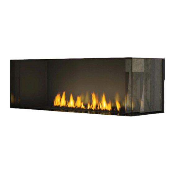
User Manuals: Regency City Series Modern Gas Fireplaces
Manuals and User Guides for Regency City Series Modern Gas Fireplaces. We have 16 Regency City Series Modern Gas Fireplaces manuals available for free PDF download: Owners & Installation Manual, Manual, Important Information Manual

Regency City Series Owners & Installation Manual (116 pages)
Brand: Regency
|
Category: Indoor Fireplace
|
Size: 11 MB
Table of Contents
Advertisement

Regency City Series Owners & Installation Manual (124 pages)
Brand: Regency
|
Category: Indoor Fireplace
|
Size: 13 MB
Table of Contents

Regency City Series Owners & Installation Manual (112 pages)
DIRECT VENT
Brand: Regency
|
Category: Indoor Fireplace
|
Size: 11 MB
Table of Contents
Advertisement
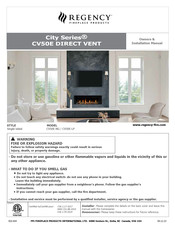
Regency City Series Owners & Installation Manual (112 pages)
Brand: Regency
|
Category: Indoor Fireplace
|
Size: 11 MB
Table of Contents
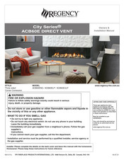
Regency City Series Owners & Installation Manual (108 pages)
DIRECT VENT
Brand: Regency
|
Category: Indoor Fireplace
|
Size: 27 MB
Table of Contents

Regency City Series Owners & Installation Manual (108 pages)
Brand: Regency
|
Category: Indoor Fireplace
|
Size: 11 MB
Table of Contents

Regency City Series Owners & Installation Manual (108 pages)
Brand: Regency
|
Category: Indoor Fireplace
|
Size: 21 MB
Table of Contents
Regency City Series Owners & Installation Manual (104 pages)
DIRECT VENT
Brand: Regency
|
Category: Indoor Fireplace
|
Size: 57 MB
Table of Contents
Regency City Series Owners & Installation Manual (96 pages)
Brand: Regency
|
Category: Indoor Fireplace
|
Size: 17 MB
Table of Contents

Regency City Series Owners & Installation Manual (92 pages)
City Series CV72E POWER VENT
Brand: Regency
|
Category: Indoor Fireplace
|
Size: 19 MB
Table of Contents
Regency City Series Owners & Installation Manual (89 pages)
Zero Clearance Direct Vent Gas Fireplace
Brand: Regency
|
Category: Indoor Fireplace
|
Size: 16 MB
Table of Contents

Regency City Series Owners & Installation Manual (84 pages)
Zero Clearance Direct Flue Gas Fireplace
Brand: Regency
|
Category: Indoor Fireplace
|
Size: 10 MB
Table of Contents
Regency City Series Owners & Installation Manual (88 pages)
Direct Vent Gas Power Vent Fireplace, Style: Left Corner/Right Corner
Brand: Regency
|
Category: Indoor Fireplace
|
Size: 16 MB
Table of Contents
Regency City Series Manual (31 pages)
Direct Vent Gas Fireplace
Brand: Regency
|
Category: Indoor Fireplace
|
Size: 2 MB
Table of Contents

Regency City Series Important Information Manual (29 pages)
Brand: Regency
|
Category: Indoor Fireplace
|
Size: 9 MB
Table of Contents

Regency City Series Manual (9 pages)
Brand: Regency
|
Category: Indoor Fireplace
|
Size: 1 MB
Advertisement