Sign In
Upload
Manuals
Brands
Reer Manuals
Controller
MOSAIC Master M1
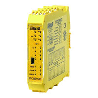
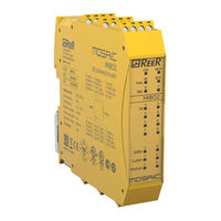
Reer MOSAIC Master M1 Manuals
Manuals and User Guides for Reer MOSAIC Master M1. We have
8
Reer MOSAIC Master M1 manuals available for free PDF download: Installation And Use Manual, Manual, Quick Installation Manual
Reer MOSAIC Master M1 Installation And Use Manual (266 pages)
MODULAR SAFETY INTEGRATED CONTROLLER
Brand:
Reer
| Category:
Controller
| Size: 19 MB
Table of Contents
Table of Contents
2
Introduction
9
Contents of this Handbook
9
Important Safety Instructions
9
Abbreviations and Symbols
10
Applicable Standards
11
Overview
12
Master MOSAIC M1 / MOSAIC M1S / MOSAIC M1S COM
12
MOSAIC M1S COM Key Features
13
MOSAIC M1S COM and Mbx in the same Project: Fieldbus Management
14
Expansion Modules
14
MSD Software
15
Product Composition
16
Installation
17
MOSAIC M1, MOSAIC M1S, Expansion Modules Mechanical Fastening
17
MOSAIC M1S COM Mechanical Fastening
18
Calculation of Safety Distance of an ESPE Connected to MOSAIC
19
Electrical Connections
19
Instructions Concerning Connection Cables
20
Master Module MOSAIC M1
20
Master Modules MOSAIC M1S / MOSAIC M1S COM
21
USB Interface
22
LAN Interface (RJ45)
22
MOSAIC Configuration Memory (MCM)
22
MULTIPLE LOAD Function
22
RESTORE Function
23
Compatibility between MCM Memory and Master Modules
23
New MCM Features with F.w. 2.0.0
23
Module MI8O2
24
Module MI8O4
25
Module MI8
26
Module MI12T8
26
Module MI16
27
Module MO2
27
Module MO4
28
Module MO4L
28
Module MR2
29
Module MR4
29
Module MR8
30
Modules MV0 - MV1 - MV2
31
Encoder Connections with RJ45 Connector (MV1, MV2)
31
Module MOR4
33
Module MOR4S8
33
Module MOS8
34
Module MOS16
34
Module MO4LHCS8
35
Modulo MA2
35
Modulo MA4
36
MA2 / MA4 Analog Sensor Connections
37
Example of Connection of Mosaic to the Machine Control System
38
Checklist after Installation
38
Operating Diagram
39
Signals
40
Inputs
40
Master Enable
40
Node Sel
40
Proximity Input for Speed Controller MV
40
Configuration with Interleaved Proximity
41
Restart_Fbk
41
Outputs
42
OUT STATUS (SIL 1/PL C)
42
Out Test
42
Ossd Safety Outputs
43
Important Note Concerning OSSD Safety Outputs
43
Ossd (Mosaic M1, Mi8O2, Mo2, Mo4)
43
Ossd (Mosaic M1S, Mosaic M1S Com, Mi8O4, Mo4L)
43
Ossd (Mo4Lhcs8)
45
Ossd Outputs Configuration
46
Safety Relays (Mr2, Mr4, Mr8, Mor4, Mor4S8)
47
Characteristics of the Output Circuit
47
MR2/MR4/MR8 Internal Contacts Diagram
47
Example of MR2 Module Connection with Static OSSD of a Module MOSAIC M1
48
Switching Operation Timing Diagram
49
Technical Features
50
General System Characteristics
50
Safety Level Parameters
50
General Data
50
Enclosure
51
MOSAIC M1 Module
52
MOSAIC M1S Module
52
MOSAIC M1S COM Module
53
MI8O2 Module
53
MI8O4 Module
54
MI8 - MI16 Modules
54
MI12T8 Module
54
MO2 - MO4 Modules
55
MO4L Module
55
MOS8 - MOS16 Modules
55
MR2 - MR4 - MR8 Modules
56
MOR4 - MOR4S8 Module
56
MO4LHCS8 Module
57
MV0 - MV1 - MV2 Modules
57
MA2, MA4 Module
58
Mechanical Dimensions
59
LED INDICATORS (Normal Operation)
60
Master MOSAIC M1 (Figure 20)
60
Master MOSAIC M1S (Figure 20)
61
Master MOSAIC M1S COM (Figure 20)
62
MOSAIC M1S COM Specific Fieldbus LED Indicators
63
Ethercat Leds
63
LED State Explanation
63
Ethernet/Ip Leds
64
LED State Explanation
65
Modbus/Tcp Leds
65
PROFINET Leds
66
LED State Explanation
66
MI8O2 (Figure 23)
67
MI8O4 (Figure 23)
68
MI8 (Figure 25)
69
MI12T8 (Figure 27)
70
MI16 (Figure 27)
71
MO2 (Figure 28)
72
MO4 (Figure 29)
73
MO4L (Figure 23)
74
MOR4 (Figure 31)
75
MOR4S8 (Figure 32)
76
MOS8 (Figure 33)
77
MOS16 (Figure 34)
78
MV0, MV1, MV2 (Figure 35)
79
MR2, MR4, MR8 (Figure 36)
80
MO4LHCS8 (Figure 37)
81
MA2, MA4 (Figure 38)
82
LED INDICATORS (Troubleshooting)
83
Master MOSAIC M1 (Figure 39)
83
Master MOSAIC M1S / MOSAIC M1S COM (Figure 40)
84
MI8O2 (Figure 41)
85
MI8O4 (Figure 42)
86
MI8 (Figure 43)
87
MI12T8 (Figure 44)
88
MI16 (Figure 45)
89
MO2 / MO4 (Figure 46)
90
MO4L (Figure 47)
91
MOR4 (Figure 48)
92
MOR4S8 (Figure 49)
93
MOS8 (Figure 50)
94
MOS16 (Figure 51)
95
MV0, MV1, MV2 (Figure 52)
96
MO4LHCS8 (Figure 53)
97
MA2, MA4 (Figure 54)
98
Mosaic Safety Designer Software
100
Installing the Software
100
PC HARDWARE Requirements
100
PC SOFTWARE Requirements
100
Installation of MSD Software
100
Fundamentals
101
Standard Toolbar
102
Textual Toolbar
103
Create a New Project (Configure the MOSAIC System)
103
Pages Configuration / Management
104
Fieldbus with Dynamic Input Order
106
Create a New Project: MOSAIC M1S COM Fieldbus Parameters Configuration
106
Modbus TCP Parameters
106
Ethernet/Ip Parameters
107
Profinet RT Parameters
107
Ethercat Parameters
108
Edit Configuration (Composition of the Various Modules)
109
Change User Parameters
109
Objects - Operator - Configuration Toolbars
110
Creating the Diagram
111
Use of Mouse Right Button
112
Example of a Project
113
Project Validation
113
Resources Allocation
114
Project Report
115
Connect MSD to Mosaic Master
117
Communication Channel Selection
117
USB Connection
117
Network Connection (MOSAIC M1S COM Only)
117
Connected Master Parameters Visualization
121
MOSAIC M1S COM Connected Via LAN
121
MOSAIC M1S COM Connected Via USB
121
MOSAIC M1/MOSAIC M1S Connected Via USB
122
Operations Available with Master Connected (MOSAIC M1S COM)
123
Visualization Network Parameters
123
Visualization/Setting Network Parameters (MOSAIC M1S COM)
123
Download Project to MOSAIC (from PC)
124
Upload an Existing Project to PC (from MOSAIC)
125
Configurations LOG
125
System Composition
125
Errors Log
126
Disconnecting System
126
Monitor Functions
126
Monitor (I/O Status in Real Time - Textual)
126
Monitor (I/O Status in Real Time - Textual - Graphic)
127
Monitor (I/O with Diagnostic)
127
Fieldbus Monitor (Only for MOSAIC M1S COM)
128
Password Protection
129
Level 1 Password
129
Level 2 Password
130
Maintenance Password (MOSAIC M1S, MOSAIC M1S COM)
130
Password Change
130
Testing the System
131
Object Function Blocks
132
Output Objects
132
OSSD (Safety Outputs)
132
SINGLE-DOUBLE OSSD (Safety Output)
133
STATUS (SIL 1/PL C Output)
136
Fieldbus Probe
137
Relay
138
Use with RESTART: Automatic (A) or Manual (B) (Category 2)
139
Input Objects
141
E-STOP (Emergency Stop)
141
E-GATE (Safety Gate Device)
142
SINGLE E-GATE (Safety Gate Device)
143
Lock Feedback
144
ENABLE (Enable Key)
145
ESPE (Optoelectronic Safety Light Curtain / Laser Scanner)
146
FOOTSWITCH (Safety Pedal)
147
MOD-SEL (Safety Selector)
149
PHOTOCELL (Safety Photocell)
149
TWO-HAND (Bimanual Control)
150
Network_In
151
Sensor
151
S-MAT (Safety Mat)
152
Switch
153
Enabling Grip Switch
154
Testable Safety Device
155
RFID (RFID Safety Sensor)
157
Solid State Device
158
Advertisement
Reer MOSAIC Master M1 Installation And Use Manual (239 pages)
MODULAR SAFETY INTEGRATED CONTROLLER
Brand:
Reer
| Category:
Controller
| Size: 15 MB
Table of Contents
Table of Contents
2
Introduction
8
Contents of this Handbook
8
Important Safety Instructions
8
Abbreviations and Symbols
9
Applicable Standards
9
Overview
10
Product Composition
13
Installation
14
Mechanical Fastening
14
Calculation of Safety Distance of an ESPE Connected to MOSAIC
15
Electrical Connections
15
Instructions Concerning Connection Cables
16
Master Module M1
16
Master Module M1S
17
USB Input
18
MOSAIC Configuration Memory (MCM)
18
MULTIPLE LOAD Function
18
RESTORE Function
19
Module MI8O2
19
Module MI8O4
20
Module MI8
20
Module MI12T8
21
Module MI16
21
Module MO2
22
Module MO4
22
Module MO4L
23
Module MR2
24
Module MR4
24
Module MR8
25
Modules MV0 - MV1 - MV2
26
Encoder Connections with Rj45 Connector (Mv1, Mv2)
27
Module MOR4
28
Module MOR4S8
28
Module MOS8
29
Module MOS16
29
Module MO4LHCS8
30
Modulo MA2
30
Modulo MA4
31
MA2 / MA4 Analog Sensor Connections
32
Example of Connection of Mosaic to the Machine Control System
33
Checklist after Installation
33
Operating Diagram
34
Signals
35
Inputs
35
Master Enable
35
Node Sel
35
Proximity Input for Speed Controller MV
36
Configuration with Interleaved Proximity
36
Restart_Fbk
37
Outputs
38
OUT STATUS (SIL 1/PL C)
38
Out Test
38
Ossd Safety Outputs
38
Important Note Concerning Ossd Safety Outputs
38
Ossd (M1, Mi8O2, Mo2, Mo4)
39
Ossd (M1S, Mi8O4, Mo4L)
39
Ossd (Mo4Lhcs8)
41
Ossd Outputs Configuration
42
Safety Relays (Mr2, Mr4, Mor4, Mor4S8)
43
Characteristics of the Output Circuit
43
MR2/MR4/MR8 Internal Contacts Diagram
43
Example of MR2 Module Connection with Static OSSD Outputs of a Module M1
44
Switching Operation Timing Diagram
45
Technical Features
46
General System Characteristics
46
Safety Level Parameters
46
General Data
46
Enclosure
47
M1 Module
47
M1S Module
48
MI8O2 Module
48
MI8O4 Module
48
MI8 - MI16 Modules
49
MI12T8 Module
49
MO2 - MO4 Modules
49
MO4L Module
49
MOS8 MOS16 Modules
50
MR2 - MR4 MR8 Modules
50
MOR4 MOR4S8 Module
50
MO4LHCS8 Module
51
MV0 - MV1 - MV2 Modules
51
MA2, MA4 Module
52
Mechanical Dimensions
53
LED INDICATORS (Normal Operation)
54
Master M1 (Figure 16)
54
Master M1S (Figure 16)
55
MI8O2 (Figure 18)
56
MI8O4 (Figure 18)
57
MI8 (Figure 20)
58
MI12T8 (Figure 22)
59
MI16 (Figure 22)
60
MO2 (Figure 23)
61
MO4 (Figure 24)
62
MO4L (Figure 18)
63
MOR4 (Figure 26)
64
MOR4S8 (Figure 27)
65
MOS8 (Figure 28)
66
MOS16 (Figure 29)
67
MV0, MV1, MV2 (Figure 30)
68
MR2, MR4, MR8 (Figure 31)
69
MO4LHCS8 (Figure 32)
70
MA2, MA4 (Figure 33)
71
LED INDICATORS (Troubleshooting)
72
Master M1 (Figure 34)
72
Master M1S (Figure 35)
73
MI8O2 (Figure 36)
74
MI8O4 (Figure 37)
75
MI8 (Figure 38)
76
MI12T8 (Figure 39)
77
MI16 (Figure 40)
78
MO2 / MO4 (Figure 41)
79
MO4L (Figure 42)
80
MOR4 (Figure 43)
81
MOR4S8 (Figure 44)
82
MOS8 (Figure 45)
83
MOS16 (Figure 46)
84
MV0, MV1, MV2 (Figure 47)
85
MO4LHCS8 (Figure 48)
86
MA2, MA4 (Figure 49)
87
Reer MOSAIC Master M1 Installation And Use Manual (170 pages)
modular safety controller
Brand:
Reer
| Category:
Controller
| Size: 9 MB
Table of Contents
Table of Contents
2
Introduction
7
Contents of this Handbook
7
Important Safety Instructions
7
Abbreviations and Symbols
8
Applicable Standards
8
Overview
9
Product Composition
11
Installation
12
Mechanical Fastening
12
Calculation of Safety Distance of an ESPE Connected to MOSAIC
13
Electrical Connections
13
Instructions Concerning Connection Cables
14
Module Master M1
14
USB Input
15
MOSAIC Configuration Memory (MCM)
15
MULTIPLE LOAD Function
15
RESTORE Function
15
Module MI8O2
16
Module MI8
17
Module MI12T8
17
Module MI16
18
Module MO4
18
Module MO2
19
Module MR4
19
Module MR2
20
Modules MV0 - MV1 - MV2
20
Encoder Connections with Rj45 Connector (Mv1, Mv2)
21
Module MOR4
22
Module MOR4S8
22
Module MOS8
23
Module MOS16
23
Module MO4LHCS8
24
Example of Connection of Mosaic to the Machine Control System
24
Checklist after Installation
24
Operating Diagram
25
Signals
26
Inputs
26
Master Enable
26
Node Sel
26
Proximity Input for Speed Controller MV
27
Configuration with Interleaved Proximity (Figure 5)
27
Restart_Fbk
28
Outputs
29
Out Status
29
Out Test
29
Ossd (M1, Mi8O2)
29
Ossd (Mo2, Mo4)
29
Ossd (Mo4Lhcs8)
30
Safety Relays (Mr2, Mr4, Mor4, Mor4S8)
31
Characteristics of the Output Circuit
31
MR2/MR4 Internal Contacts Diagram
31
Example of MR2 Module Connection with Static OSSD Outputs of a Module M1
32
Switching Operation Timing Diagram
32
Technical Features
33
General System Characteristics
33
Safety Level Parameters
33
General Data
33
Enclosure
34
M1 Module
34
MI8O2 Module
34
MI8 - MI16 Modules
35
MI12T8 Module
35
MO2 - MO4 Modules
35
MOS8 MOS16 Modules
35
MR2 - MR4 Modules
36
MOR4 MOR4S8 Module
36
MO4LHCS8 Module
37
MV0 - MV1 - MV2 Modules
37
Mechanical Dimensions
38
Signals
39
Master M1 (Figure 11)
39
MI8O2 (Figure 12)
40
MI8 (Figure 13)
41
MI12T8 (Figure 15)
42
MI16 (Figure 15)
43
MO2 (Figure 16)
44
MO4 (Figure 17)
45
MOR4 (Figure 18)
46
MOR4S8 (Figure 19)
47
MOS8 (Figure 20)
48
MOS16 (Figure 21)
49
MV1, MV2 (Figure 22)
50
MR2 (Figure 23) / MR4 (Figure 24)
51
MO4LHCS8 (Figure 25)
52
Troubleshooting
53
Master M1 (Figure 26)
53
MI8O2 (Figure 27)
54
MI8 (Figure 28)
55
MI12T8 (Figure 29)
56
MI16 (Figure 30 - MI16)
57
MO2 / MO4 (Figure 31)
58
MOR4 (Figure 32)
59
MOR4S8 (Figure 33)
60
MOS8 (Figure 34)
61
MOS16 (Figure 35)
62
MV0, MV1, MV2 (Figure 33)
63
MO4LHCS8 (Figure 37)
64
Advertisement
Reer MOSAIC Master M1 Installation And Use Manual (143 pages)
MODULAR SAFETY INTEGRATED CONTROLLER
Brand:
Reer
| Category:
Controller
| Size: 9 MB
Table of Contents
Table of Contents
2
Contents of this Handbook
6
Important Safety Instructions
6
Abbreviations and Symbols
7
Applicable Standards
7
Mechanical Fastening
11
Calculation of Safety Distance of an ESPE Connected to MOSAIC
12
Electrical Connections
12
Instructions Concerning Connection Cables
13
USB Input
14
MOSAIC Configuration Memory (MCM)
14
MULTIPLE LOAD Function
14
RESTORE Function
14
Encoder Connections with Rj45 Connector (Mv1, Mv2)
20
Example of Connection of Mosaic to the Machine Control System
23
Checklist after Installation
23
Inputs
25
Master Enable
25
Node Sel
25
Proximity Input for Speed Controller MV
26
Configuration with Interleaved Proximity (Figure 5)
26
Restart_Fbk
27
Outputs
28
Out Status
28
Out Test
28
Ossd (M1, Mi8O2)
28
Ossd (Mo2, Mo4)
28
Safety Relays (Mr2, Mr4, Mor4, Mor4S8)
29
Characteristics of the Output Circuit
29
MR2/MR4 Internal Contacts Diagram
29
Example of MR2 Module Connection with Static OSSD Outputs of a Module M1
30
Switching Operation Timing Diagram
30
General System Characteristics
31
Safety Level Parameters
31
General Data
31
Enclosure
32
M1 Module
32
MI8O2 Module
32
MI8 - MI16 Modules
33
MI12T8 Module
33
MO2 - MO4 Modules
33
MOS8 - MOS16 Modules
33
MR2 - MR4 Modules
34
MOR4 - MOR4S8 Module
34
MV0 - MV1 - MV2 Modules
35
Mechanical Dimensions
36
Signals
37
Master M1 (Figure 11)
37
MI8O2 (Figure 12)
38
MI8 (Figure 13)
39
MI12T8 (Figure 15)
40
MI16 (Figure 15)
41
MO2 (Figure 16)
42
MO4 (Figure 17)
43
MOR4 (Figure 18)
44
MOR4S8 (Figure 19)
45
MOS8 (Figure 20)
46
MOS16 (Figure 21)
47
MV1, MV2 (Figure 22)
48
MR2 (Figure 23) / MR4 (Figure 24)
49
Troubleshooting
50
Master M1 (Figure 25)
50
MI8O2 (Figure 26)
51
MI8 (Figure 27)
52
MI12T8 (Figure 28)
53
MI16 (Figure 29 - MI16)
54
MO2 / MO4 (Figure 30)
55
MOR4 (Figure 31)
56
MOR4S8 (Figure 32)
57
MOS8 (Figure 33)
58
MOS16 (Figure 34)
59
MV0, MV1, MV2 (Figure 32)
60
Installing the Software
61
PC HARDWARE Requirements
61
PC SOFTWARE Requirements
61
How to Install MSD
61
Fundamentals
62
Standard Tool Bar
63
Textual Tool Bar
64
Create a New Project (Configure the MOSAIC System)
64
EDIT CONFIGURATION (Composition of the Various Modules)
65
Change User Parameters
65
OBJECTS - OPERATOR - CONFIGURATION Tool Bars
66
Creating the Diagram
67
Use of Mouse Right Button
67
Example of a Project
69
Project Validation
69
Project Report
70
Connect to Mosaic
71
Sending the Configuration to the MOSAIC
71
Download a Configuration File (Project) from Mosaic M1
71
Configuration LOG
71
System Composition
72
Disconnecting System
72
MONITOR (I/O Status in Real Time - Textual)
72
MONITOR (I/O Status in Real Time - Textual - Graphic)
73
Password Protection
74
Level 1 Password
74
Level 2 Password
74
Password Change
74
TESTING the System
75
Reer MOSAIC Master M1 Installation And Use Manual (170 pages)
MODULAR SAFETY INTEGRATED CONTROLLER
Brand:
Reer
| Category:
Controller
| Size: 16 MB
Table of Contents
Module Master M1
14
MULTIPLE LOAD Function
15
RESTORE Function
15
Module MI12T8
17
Encoder Connections with Rj45 Connector (Mv1, Mv2)
21
Module MOS8
23
Module MOS16
23
Module MO4LHCS8
24
Example of Connection of Mosaic to the Machine Control System
24
Proximity Input for Speed Controller MV
27
Configuration with Interleaved Proximity (Figure 5)
27
Characteristics of the Output Circuit
31
General System Characteristics
33
Safety Level Parameters
33
General Data
33
MI8O2 Module
34
MI12T8 Module
35
MOR4 - MOR4S8 Module
36
MO4LHCS8 Module
37
EDIT CONFIGURATION (Composition of the Various Modules)
69
Change User Parameters
69
On Block Input / Output
71
On Block Operators
71
On Connection (Wires)
72
Example of a Project
73
Project Validation
73
Project Report
74
Configuration LOG
75
System Composition
76
Disconnecting System
76
OSSD (Safety Outputs)
81
SINGLE OSSD (Safety Output)
82
STATUS (Signal Output)
84
Fieldbus Probe
84
E-GATE (Safety Gate Device)
89
SINGLE E-GATE (Safety Gate Device)
90
Lock Feedback
91
ENABLE (Enable Key)
92
FOOTSWITCH (Safety Pedal)
94
MOD-SEL (Safety Selector)
96
PHOTOCELL (Safety Photocell)
96
TWO-HAND (Bimanual Control)
97
S-MAT (Safety Mat)
99
Enabling Grip Switch
101
Item Description
102
Testable Safety Device
102
Solid State Device
103
Fieldbus Input
104
Warning Concerning Safety
106
Speed Control
107
Window Speed Control
109
Stand Still and Speed Control
113
Logical Operators
115
Reer MOSAIC Master M1 Installation And Use Manual (93 pages)
MODULAR SAFETY INTEGRATED CONTROLLER
Brand:
Reer
| Category:
Controller
| Size: 6 MB
Table of Contents
Table of Contents
3
Introduction
6
Contents of this Handbook
6
Important Safety Instructions
6
Abbreviations and Symbols
7
Applicable Standards
7
Overview
8
Product Composition
9
Installation
10
Mechanical Fastening
10
Calculation of Safety Distance of an ESPE Connected to MOSAIC
11
Electrical Connections
11
Instructions Concerning Connection Cables
12
USB Input
13
MOSAIC Configuration Memory (MCM)
13
MULTIPLE LOAD Function
13
RESTORE Function
13
Th June 2012 • Rev
15
Example of Connection of Mosaic to the Machine Control System
19
Checklist after Installation
19
Operating Diagram
20
Signals
21
Inputs
21
Master Enable
21
Node Sel
21
Restart_Fbk
22
Outputs
23
Out Status
23
Out Test
23
Ossd (M1, Mi8O2)
23
Ossd (Mo2, Mo4)
23
Safety Relays (Mr2, Mr4)
24
Characteristics of the Output Circuit
24
MR2/MR4 Internal Contacts Diagram
24
Example of MR2 Module Connection with Static OSSD Outputs of a Module M1
25
Switching Operation Timing Diagram
25
Technical Features
26
General System Characteristics
26
Safety Level Parameters
26
General Data
26
Enclosure
27
M1 Module
27
MI8O2 Module
27
MI8 - MI16 Modules
28
MI12T8 Module
28
MO2 - MO4 Modules
28
MR2 - MR4 Modules
28
Mechanical Dimensions
29
Signals
30
Master M1 (Figure 10)
30
MI8O2 (Figure 11)
31
MI8 (Figure 12)
32
MI12T8 (Figure 14)
33
MI16 (Figure 14)
34
MO2 (Figure 15)
35
MO4 (Figure 16)
36
MR2 (Figure 17) / MR4 (Figure 18)
37
Troubleshooting
38
Master M1 (Figure 19)
38
MI8O2 (Figure 20)
39
MI8 (Figure 21)
40
MI12T8 (Figure 22)
41
MI16 (Figure 23 - MI16)
42
MO2 / MO4 (Figure 24)
43
Mosaic Safety Designer Software
44
Installing the Software
44
PC HARDWARE Requirements
44
PC SOFTWARE Requirements
44
How to Install MSD
44
Fundamentals
45
Standard Tool Bar
46
Textual Tool Bar
47
Create a New Project (Configure the MOSAIC System)
47
EDIT CONFIGURATION (Composition of the Various Modules)
48
Change User Parameters
48
OBJECTS - OPERATOR - CONFIGURATION Tool Bars
49
Creating the Diagram (Figure 16)
50
Example of a Project
51
Project Validation
51
Project Report
52
Connect to Mosaic
53
Sending the Configuration to the MOSAIC
53
Download a Configuration File (Project) from Mosaic M1
53
Configuration LOG
53
System Composition
54
Disconnecting System
54
MONITOR (I/O Status in Real Time - Textual)
55
MONITOR (I/O Status in Real Time - Textual - Graphic)
55
Password Protection
56
Level 1 Password
56
Level 2 Password
56
Password Change
56
TESTING the System
57
Object Function Blocks
58
Output Objects
58
OSSD (Safety Outputs)
58
STATUS (Signal Output)
58
Fieldbus Probe
58
Input Objects
59
E-STOP (Emergency Stop)
59
E-GATE (Safety Gate Device)
60
ENABLE (Enable Key)
61
ESPE (Optoelectronic Safety Light Curtain / Laser Scanner)
62
FOOTSWITCH (Safety Pedal)
64
MOD-SEL (Safety Selector)
65
PHOTOCELL (Safety Photocell)
65
TWO-HAND (Bimanual Control)
67
Sensor
67
S-MAT (Safety Mat)
69
Switch
70
Enabling Grip Switch
71
Testable Safety Device
72
Solid State Device
74
Fieldbus Input
75
Comments
75
Title
75
Operator Function Blocks
76
Logical Operators
76
And
76
Nand
76
Not
77
Nor
77
Xor
78
Xnor
78
Multiplexer
78
Memory Operators
79
D FLIP FLOP (Max Number = 16)
79
Sr Flip Flop
80
USER RESTART MANUAL (Max Number = 16 with RESTART MONITORED)
80
USER RESTART MONITORED (Max Number = 16 with RESTART MANUAL)
80
Counter Operators
81
COUNTER Operator Is a Pulse Counter that Sets Output Q to 1 (TRUE) as Soon as the Desired Count Is Reached
81
COUNTER (Max Number = 16)
81
TIMER OPERATORS (Max Number = 16)
81
Clocking
81
Monostable
82
Passing Make Contact
83
Delay
84
MUTING OPERATORS (Max Number = 4)
85
Concurrent" MUTING
85
Muting "L
86
Sequential" MUTING
87
Muting "T
88
MUTING OVERRIDE (Max Number = 16)
89
Special Applications
90
Output Delay with Manual
90
Reer MOSAIC Master M1 Quick Installation Manual (20 pages)
Master Module - Modular Safety Controller
Brand:
Reer
| Category:
Controller
| Size: 1 MB
Table of Contents
Table of Contents
3
Mosaic M1 Modulo Master
4
Importanti Avvertenze Sulla Sicurezza
4
Introduzione
5
Collegamenti Elettrici
5
Avvertenze Sui Cavi DI Collegamento
6
Installazione del Software
7
Caratteristiche Hardware Richieste Per Il Pc da Collegare
7
Caratteristiche Software Richieste Per Il Pc da Collegare
7
Ingressi
7
Connettore Usb
7
Mosaic Configuration Memory (MCM)
7
Master Enable
7
Restart_Fbk
8
Uscite
8
Out Status
8
Out Test
8
Ossd (Moduli M1, Mi8O2, Mo2, Mo4)
8
Checklist Dopo L'installazione
9
Caratteristiche Tecniche
10
Mosaic M1 Master Module
11
Important Safety Instructions
11
Overview
12
Electrical Connections
12
Instructions Concerning Connection Cables
13
Installing the Software
14
Pc Hardware Requirements
14
Pc Software Requirements
14
Inputs
14
Usb Connector
14
Mosaic Configuration Memory (MCM)
14
Master Enable
14
Restart_Fbk
15
Outputs
15
Out Status
15
Out Test
15
Ossd (Module M1, Mi8O2, Mo2, Mo4)
15
Checklist after Installation
16
Technical Features
17
Dichiarazione DI Conformità / Declaration of Conformity
18
Reer MOSAIC Master M1 Manual (22 pages)
FIELDBUS MODULES
Brand:
Reer
| Category:
Controller
| Size: 3 MB
Table of Contents
Table of Contents
1
Introduction
2
Electrical Connections
2
Protocol Data Package Composition
3
Footprint in Input
4
Footprint in Output
4
Selector Data
7
MV Modules Input Status
7
Diagnostics
8
The "I/O Index" Field
8
The "Diagnostic Code" Field
8
Signals and Pinout
10
Module MBC
10
Module MBD
11
Module MBP
11
Module MBEC
12
Module MBEI
12
Module MBEI2B
13
Module MBEP
13
Module MBEP2
14
Module MBEM
14
Module MBMR
15
Module MBU
15
Examples of Diagnostics
16
Example 1
16
Example 2
16
Example 3
17
Bus Configurator User Interface
17
Graphic Interface
18
Examples of Msd Configuration as Presented by the Bus Configurator
22
Advertisement
Related Products
Reer MOSAIC M1S
Reer MOSAIC MI8O2
Reer MOSAIC MI12T8
Reer MOSAIC MI8
Reer MOSAIC MR4
Reer Mosaic
Reer Mosaic MBEP
Reer Mosaic MC25
Reer Mosaic MCT1
Reer MOSAIC MV1TB
Reer Categories
Safety Equipment
Baby Monitor
Thermometer
Security Sensors
Control Unit
More Reer Manuals
Login
Sign In
OR
Sign in with Facebook
Sign in with Google
Upload manual
Upload from disk
Upload from URL