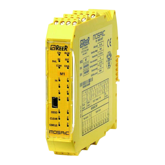
Page 13
MODULAR SAFETY INTEGRATED CONTROLLER MOSAIC Positioning of safeguards with respect to the approach speeds of parts of the human body. 8540780 • 07/05/2018 • Rev.33...
MODULAR SAFETY INTEGRATED CONTROLLER MOSAIC Module MO4LHCS8 Example of connection of Mosaic to the machine control system Figure 4 Operate a complete system TEST (see "TESTING the system") Verify that all the cables are correctly inserted and the terminal blocks well screwed. Verify that all the leds (indicators) light on correctly.
MODULAR SAFETY INTEGRATED CONTROLLER MOSAIC GENERAL SYSTEM CHARACTERISTICS Safety level parameters General data Ω This response times depends on the following parameters: 1) Number of Slave modules installed 2) Number of Operators 3) Number of OSSD outputs For the right response time refer to the one calculated by the DSD software (see Project report) This parameter corresponds to the response time, with the exception of MV modules with...
Page 77
MODULAR SAFETY INTEGRATED CONTROLLER MOSAIC MONITOR (I/O status in real time - textual) Figure 51 - textual monitor MONITOR (I/O status in real time - textual - graphic) PARTICULAR CASES 8540780 • 07/05/2018 • Rev.33...
MODULAR SAFETY INTEGRATED CONTROLLER MOSAIC Enable Error Out STATUS (signal output) FIELDBUS PROBE (For more detailed information, consult the fieldbus manual on the MSD CD-ROM). 8540780 • 07/05/2018 • Rev.33...
Page 85
MODULAR SAFETY INTEGRATED CONTROLLER MOSAIC RELAY Parameters Category • • • Example with external relay Example with the internal relay only • • • (Output Test Equipment) OTE: 8540780 • 07/05/2018 • Rev.33...
Page 86
MODULAR SAFETY INTEGRATED CONTROLLER MOSAIC Use with RESTART: Automatic (A) or Manual (B) (Category 2) Figure 55 • • • 8540780 • 07/05/2018 • Rev.33...
MODULAR SAFETY INTEGRATED CONTROLLER MOSAIC * Simultaneity error = the maximum time between switching of the single contacts has been exceeded. Parameters Manual Reset: Power-on test Filter (ms): With simultaneity: Simultaneity (ms) Enable Error Out: Item description: SOLID STATE DEVICE Parameters Manual Reset: 8540780 •...
Page 108
MODULAR SAFETY INTEGRATED CONTROLLER MOSAIC (In order to ensure a Performance Level = PLe use a proximity switch type PNP NO: ref. “Interleaved proximity -> page 27). Proximity choice: f = frequency [rev/m in] Rpm = rotational speed [Hz] ...
MODULAR SAFETY INTEGRATED CONTROLLER MOSAIC WINDOW SPEED CONTROL Parameters (In order to ensure a Performance Level = PLe use a proximity switch type PNP NO: ref. “Interleaved proximity -> page 27). Proximity choice 8540780 • 07/05/2018 • Rev.33...
Page 111
MODULAR SAFETY INTEGRATED CONTROLLER MOSAIC STAND STILL Parameters (In order to ensure a Performance Level = PLe use a proximity switch type PNP NO: ref. “Interleaved proximity -> page 25). 8540780 • 07/05/2018 • Rev.33...
MODULAR SAFETY INTEGRATED CONTROLLER MOSAIC STAND STILL AND SPEED CONTROL Parameters Example of CLOCKWISE axis rotation 2 threshold settings Threshold no. Speed 1 Speed 2 4 threshold settings Threshold no. Speed 1 Speed 2 Speed 3 Speed 4 8540780 • 07/05/2018 • Rev.33...
Page 114
MODULAR SAFETY INTEGRATED CONTROLLER MOSAIC (In order to ensure a Performance Level = PLe use a proximity switch type PNP NO: ref. “Interleaved proximity -> page 27). Proximity choice: f = frequency Rpm = rotational speed [rev/m in] Resolution = measurement [Hz] ...
MODULAR SAFETY INTEGRATED CONTROLLER MOSAIC Parameters Number of inputs XNOR Parameters Number of inputs LOGICAL MACRO Parameters Logic inputs 1, 2: 8540780 • 07/05/2018 • Rev.33...
Page 118
MODULAR SAFETY INTEGRATED CONTROLLER MOSAIC Select Logic 1, 2, 3: Enable (OUT1, OUT2) MULTIPLEXER In n In n Parameters Number of inputs 8540780 • 07/05/2018 • Rev.33...
MODULAR SAFETY INTEGRATED CONTROLLER MOSAIC USER RESTART MANUAL (max number = 16 with other RESTART operators) Parameters Clear enable USER RESTART MONITORED (max number = 16 with other RESTART operators) Parameters Clear enable (max number = 16 with other RESTART operators) MACRO RESTART MANUAL 8540780 •...
MODULAR SAFETY INTEGRATED CONTROLLER MOSAIC GUARD LOCK Description of "GUARD LOCK" operator inputs/outputs “Lock_fbk” input Figure 57 - Example of feedback of the status of the electromagnet of a guard lock. The signal received by the module is processed by the "Guard Lock" operator. 8540780 •...
Page 123
MODULAR SAFETY INTEGRATED CONTROLLER MOSAIC “Gate” input Figure 58 - Example of feedback of the status of a door/gate connected to the guard lock. The signal received by the module is processed by the "Guard Lock" operator. “Unlock_cmd” input ...
Page 124
MODULAR SAFETY INTEGRATED CONTROLLER MOSAIC “LockOut” output “ErrorOut” output Operation: general description Operation in the “no Gate” mode LOCK FEEDBACK Feedback Time UnLock Time, Feedback Time Feedback Time ≥ Electromagnet activation time 8540780 • 07/05/2018 • Rev.33...
Page 125
MODULAR SAFETY INTEGRATED CONTROLLER MOSAIC Example of operation in the “no Gate” mode Figure 59 – Example of operation in the no Gate mode 8540780 • 07/05/2018 • Rev.33...
Page 126
MODULAR SAFETY INTEGRATED CONTROLLER MOSAIC Figure 60 - Traces relative to “Guard Lock” block operation in the no gate mode. Operation in the “with Gate” mode E-GATE (safety gate device) LOCK FEEDBACK 8540780 • 07/05/2018 • Rev.33...
Page 127
MODULAR SAFETY INTEGRATED CONTROLLER MOSAIC UnLock Time, Feedback Time Feedback Time ≥ Electromagnet activation time Example of operation in the “with Gate” mode Figure 61 – Example of operation in the with Gate mode 8540780 • 07/05/2018 • Rev.33...
Page 128
MODULAR SAFETY INTEGRATED CONTROLLER MOSAIC Figure 62 - Traces relative to “Guard Lock” block operation in the with gate mode. 8540780 • 07/05/2018 • Rev.33...
Page 129
MODULAR SAFETY INTEGRATED CONTROLLER MOSAIC Operation in the “Mandatory Gate Opening” mode E-GATE (safety gate device) LOCK FEEDBACK UnLock Time, Feedback Time Feedback Time ≥ Electromagnet activation time 8540780 • 07/05/2018 • Rev.33...
Page 130
MODULAR SAFETY INTEGRATED CONTROLLER MOSAIC Example of operation in the “Mandatory Gate Opening” mode Figure 63 Example of operation in the Mandatory Gate Opening mode 8540780 • 07/05/2018 • Rev.33...
Page 131
MODULAR SAFETY INTEGRATED CONTROLLER MOSAIC Figure 64 - Traces relative to “Guard Lock” block operation in the “Mandatory gate opening mode”. 8540780 • 07/05/2018 • Rev.33...
Page 132
MODULAR SAFETY INTEGRATED CONTROLLER MOSAIC Figure 65 – Example of possible error condition in "Mandatory gate opening" mode. In this case the error condition is generated because the gate has not been opened, even though a request has been sent to unlock/lock the guard lock. Parameters 8540780 •...
Page 133
MODULAR SAFETY INTEGRATED CONTROLLER MOSAIC The guard thus continues to be locked even when the power supply is disconnected. 8540780 • 07/05/2018 • Rev.33...
MODULAR SAFETY INTEGRATED CONTROLLER MOSAIC MUTING FUNCTION The Muting function generates a temporary, automatic interruption of safety device operation in order to permit normal transit of material through the guarded opening. In other words, when the system recognizes the material and distinguishes between this and any operator (in a potentially dangerous situation), it is enabled to bypass the safety device temporarily, allowing the material to pass through the guarded opening.
Page 143
MODULAR SAFETY INTEGRATED CONTROLLER MOSAIC Blind Time , blind time Sensors Time: Minimum sensors time: MUTING “L” The activation of the Muting function occurs following interruption of the sensors S1 and S2 beam (the order does not matter) within a time range from 2s and 5s decided by the operator.
MODULAR SAFETY INTEGRATED CONTROLLER MOSAIC Sensors Time: End of Muting time Blind Time "Sequential" MUTING The activation of the Muting function occurs following sequential interruption of the sensors S1 and S2, subsequently S3 and S4 sensors (without time limit). If the pallet proceeds in the opposite direction the correct sequence is: S4, S3, S2, S1.
Page 145
MODULAR SAFETY INTEGRATED CONTROLLER MOSAIC Muting Close Blind Time , blind time MUTING “T” The activation of the Muting function occurs following interruption of the sensors S1 and S2 beam (the order does not matter) within a time range from 2s and 5s decided by the operator. The state of the Muting ends after the liberation of at least one of the two sensors.
MODULAR SAFETY INTEGRATED CONTROLLER MOSAIC Parameters Timeout (sec) Enable Sensors Time: MUTING OVERRIDE (max number = 4) The OVERRIDE function must be used when the machine stops due to incorrect Muting activation sequences with the material obstructing the guarded opening. This function activates the OSSD outputs making it possible to remove the material that is obstructing the guarded opening.
Page 147
MODULAR SAFETY INTEGRATED CONTROLLER MOSAIC Conditions to be checked for activation of Override Timeout (sec): Override mode: With OverOut: With Request: Manual Reset: 8540780 • 07/05/2018 • Rev.33...
MODULAR SAFETY INTEGRATED CONTROLLER MOSAIC NETWORK (max number = 1) START STOP Parameters With reference to the Figure 68 and Figure 69, at power-on: 1. The Net_out of the various nodes are in the 0 (FALSE) condition; 2.
Page 150
MODULAR SAFETY INTEGRATED CONTROLLER MOSAIC Response Time The max response time of the network starting from emergency stop is given by the formula: = [(212 ms x n°Master)-260ms] MASTER n°1 MASTER n°2 MASTER n°3 MASTER n°4 Emergency Stop rMASTER1 rMASTER2 rMASTER3...
Page 151
MODULAR SAFETY INTEGRATED CONTROLLER MOSAIC Figure 66 - NETWORK function block scheme example (Category 2) Figure 67 - NETWORK function block scheme example (Category 4) 8540780 • 07/05/2018 • Rev.33...
Page 152
MODULAR SAFETY INTEGRATED CONTROLLER MOSAIC Example of application in Category 2 according to ISO 13849-1: Figure 68 (years) Logical block diagram of a safety function using the network INPUT M1 n°1 M1 n°2 M1 n°3 M1 n°4 OUTPUT LOGIC (NETWORK) Example of application in Category 4 according to ISO 13849-1: 8540780 •...
Page 153
MODULAR SAFETY INTEGRATED CONTROLLER MOSAIC Figure 69 (hour Logical block diagram of a safety function using the network INPUT M1 n°1 M1 n°2 M1 n°3 M1 n°4 OUTPUT LOGIC (NETWORK) 8540780 • 07/05/2018 • Rev.33...
MODULAR SAFETY INTEGRATED CONTROLLER MOSAIC SPECIAL APPLICATIONS Output delay with manual Figure 70 - Two outputs with one delayed (in MANUAL mode) 8540780 • 07/05/2018 • Rev.33...
Page 158
MODULAR SAFETY INTEGRATED CONTROLLER MOSAIC (Speed selection) (LL0) (LL0) Figure 73 – MV frequency input How to use graphic simulation 8540780 • 07/05/2018 • Rev.33...
Page 159
MODULAR SAFETY INTEGRATED CONTROLLER MOSAIC Figure 74 – Example of a result of the graphic simulation. Figure 75 – Menu for selecting the graphic simulation mode 8540780 • 07/05/2018 • Rev.33...
MODULAR SAFETY INTEGRATED CONTROLLER MOSAIC Application example of graphic simulation Safe Area M_Press Press Start button Figure 79 - Diagram referring to the application example - Safe Area Gate comments entered by the user Press Start button Figure 80 - Stimuli file referring to the application example 8540780 •...
Page 163
MODULAR SAFETY INTEGRATED CONTROLLER MOSAIC Figure 81 - Graph produced by the simulation of the application example 8540780 • 07/05/2018 • Rev.33...
MODULAR SAFETY INTEGRATED CONTROLLER MOSAIC MOSAIC FAIL CODES The two M1microcontrollers do not see the same hw/sw configuration 2 or more same expansion modules with the same node number Exceeded max expansion modules number One or more modules have detected a change in the node number A slave module has detected an external error Errors related to memory MCM...
Page 167
MODULAR SAFETY INTEGRATED CONTROLLER MOSAIC Please, visit the website www.reer.it for the list of the authorised representative of each Country. Characteristics are subject to change without prior notice. No part of this document may be reproduced unless authorised by ReeR.
Page 168
Dichiarazione CE di conformità EC declaration of conformity Torino, 06/02/2018 REER SpA - via Carcano 32 10153 – Torino – Italy dichiara che il controllore integrato MOSAIC costituisce un dispositivo di sicurezza realizzato in conformità alle seguenti Direttive Europee: declares that the integrated controller MOSAIC is a safety device complying with the following European Directives: "Direttiva Macchine"...
Need help?
Do you have a question about the MOSAIC M1 and is the answer not in the manual?
Questions and answers