Reer MOSAIC Master M1 Installation And Use Manual
Modular safety integrated controller
Hide thumbs
Also See for MOSAIC Master M1:
- Installation and use manual (266 pages) ,
- Quick installation manual (20 pages) ,
- Manual (22 pages)
Table of Contents
Advertisement
Quick Links
Advertisement
Table of Contents

Related Manuals for Reer MOSAIC Master M1


Summary of Contents for Reer MOSAIC Master M1
- Page 1 MODULAR SAFETY INTEGRATED CONTROLLER MOSAIC 8540780 • 25th June 2012 • Rev.15...
- Page 2 Dichiarazione CE di conformità EC declaration of conformity Torino, 15/06/2010 REER SpA via Carcano 32 10153 – Torino Italy dichiara che il controllore integrato MOSAIC costituisce un dispositivo di sicurezza realizzato in conformità alle seguenti Direttive Europee: declares that the integrated controller MOSAIC is a safety device complying with the following European Directives: "Direttiva Macchine"...
-
Page 3: Table Of Contents
MODULAR SAFETY INTEGRATED CONTROLLER MOSAIC CONTENTS INTRODUCTION ..............................6 Contents of this handbook ................6 Important safety instructions ................6 Abbreviations and symbols ................7 Applicable standards ..................7 OVERVIEW ................................8 PRODUCT COMPOSITION ..........................9 INSTALLATION ..............................10 Mechanical fastening ..................10 Calculation of safety distance of an ESPE connected to MOSAIC ....... - Page 4 MODULAR SAFETY INTEGRATED CONTROLLER MOSAIC MECHANICAL DIMENSIONS ................29 SIGNALS ......................30 Master M1 (Figure 10) .................. 30 MI8O2 (Figure 11) ..................31 MI8 (Figure 12) ..................... 32 MI12T8 (Figure 14) ..................33 MI16 (Figure 14) ................... 34 MO2 (Figure 15) ................... 35 MO4 (Figure 16) ...................
- Page 5 MODULAR SAFETY INTEGRATED CONTROLLER MOSAIC E-STOP (emergency stop) ................59 E-GATE (safety gate device) ............... 60 ENABLE (enable key) .................. 61 ESPE (optoelectronic safety light curtain / laser scanner) ......62 FOOTSWITCH (safety pedal) ............... 64 MOD-SEL (safety selector) ................65 PHOTOCELL (safety photocell) ..............
-
Page 6: Introduction
Always test the complete system whenever new safety components are added (see the "TESTING the system" section, page 57). ReeR is not responsible for these operations or any risks in connection therewith. Reference should be made to the handbooks and the relative product and/or application standards to ensure correct use of devices connected to the Mosaic within the specific application. -
Page 7: Abbreviations And Symbols
MODULAR SAFETY INTEGRATED CONTROLLER MOSAIC Abbreviations and symbols MCM = MOSAIC Configuration Memory: memory chip for MOSAIC M1 (accessory) MSC = MOSAIC Safety Communication: proprietary bus for expansion units MSD = MOSAIC Safety Designer: MOSAIC configuration SW running in Windows OSSD = Output Signal Switching Device: solid state safety output MTTF... -
Page 8: Overview
With 14 expansions, the system can have up to 128 inputs, 16 dual channel safety outputs and 16 status outputs. The MASTER and its SLAVE units communicate via the 5-way MSC bus (ReeR proprietary bus), physically arranged on the rear panel of each unit. -
Page 9: Product Composition
MODULAR SAFETY INTEGRATED CONTROLLER MOSAIC PRODUCT COMPOSITION The MOSAIC M1is supplied with: • CD-ROM containing the free MSD SW, this PDF multi-language handbook and other product literature. • Multi-language installation sheet. NB: the rear panel MSC connector and MCM memory can be ordered separately as accessories. -
Page 10: Installation
MODULAR SAFETY INTEGRATED CONTROLLER MOSAIC INSTALLATION Mechanical fastening Fix the MOSAIC system units to a 35mm DIN rail as follows: 1. Connect the same number of "MSC" 5-pole rear panel connectors as the number of units to be installed. 2. Fix the train of connectors thus obtained to the Omega DIN 35mm (EN 5022) rail (hooking them at the top first). -
Page 11: Calculation Of Safety Distance Of An Espe Connected To Mosaic
MODULAR SAFETY INTEGRATED CONTROLLER MOSAIC Calculation of safety distance of an ESPE connected to MOSAIC Any Electro-sensitive Protective Equipment device connected to MOSAIC, must be positioned at a distance equal to or greater than the minimum safety distance S so that the dangerous point can be reached only after stopping the dangerous movement of the machine. -
Page 12: Instructions Concerning Connection Cables
MODULAR SAFETY INTEGRATED CONTROLLER MOSAIC Instructions concerning connection cables. Wire size range: AWG 12÷30, (solid/stranded) (UL). Use 60/75°C copper (Cu) conductor only. We recommend the use of separate power supplies for the safety module and for other electrical power equipment (electric motors, inverters, frequency converters) or other sources of disturbance. -
Page 13: Usb Input
Figure 2 - USB 2.0 front panel connector MOSAIC Configuration Memory (MCM) TECHNICAL DATA LABEL A backup memory, called MCM (optional) can be installed in the MOSAIC master M1 and used to save the SW configuration MCM LABEL parameters. The MCM is written each time a new project is sent from the PC to the M1. - Page 14 MODULAR SAFETY INTEGRATED CONTROLLER MOSAIC The LOAD and RESTORE functions can be disabled via SW. (see Figure 29) In order to be used, the expansion units must be addressed at the time of installation (see the NODE SEL section). Each time MCM is used, carefully check that the chosen configuration is the one that was planned for that particular system.
-
Page 15: Th June 2012 • Rev
MODULAR SAFETY INTEGRATED CONTROLLER MOSAIC MI8O2 TERMINAL SIGNAL TYPE DESCRIPTION OPERATION 24VDC 24VDC power supply NODE_SEL0 Input Input ("type B" according to EN 61131-2 ) Node selection NODE_SEL1 Input Input ("type B" according to EN 61131-2 ) 0VDC power supply OSSD1_A Output PNP active high... - Page 16 MODULAR SAFETY INTEGRATED CONTROLLER MOSAIC MI12T8 TERMINAL SIGNAL TYPE DESCRIPTION OPERATION 24VDC 24VDC power supply NODE_SEL0 Input Input ("type B" according to EN 61131-2 ) Node selection NODE_SEL1 Input Input ("type B" according to EN 61131-2 ) 0VDC power supply INPUT1 Input Digital input 1...
- Page 17 MODULAR SAFETY INTEGRATED CONTROLLER MOSAIC TERMINAL SIGNAL TYPE DESCRIPTION OPERATION 24VDC 24VDC power supply NODE_SEL0 Input Input ("type B" according to EN 61131-2 ) Node selection NODE_SEL1 Input Input ("type B" according to EN 61131-2 ) 0VDC power supply OSSD1_A Output PNP active high Static output 1...
- Page 18 MODULAR SAFETY INTEGRATED CONTROLLER MOSAIC TERMINAL SIGNAL TYPE DESCRIPTION OPERATION 24VDC 24VDC power supply 0VDC power supply OSSD1_A Input Control ZONE 1 PNP active high OSSD1_B Input FBK_K1_K2_1 Output Feedback K1K2 ZONE 1 A_NC1 Output NC contact ZONE 1 B_NC1 Output A_NO11 Output...
-
Page 19: Example Of Connection Of Mosaic To The Machine Control System
MODULAR SAFETY INTEGRATED CONTROLLER MOSAIC EXAMPLE OF CONNECTION OF MOSAIC TO THE MACHINE CONTROL SYSTEM Figure 4 CHECKLIST AFTER INSTALLATION The MOSAIC system is able to detect the faults that occurs in each own module. Anyway to have the system perfect operation perform the following checks at start up and at least every one year: Operate a complete system TEST (see "TESTING the system") Verify that all the cables are correctly inserted and the terminal blocks well screwed. -
Page 20: Operating Diagram
MODULAR SAFETY INTEGRATED CONTROLLER MOSAIC OPERATING DIAGRAM Mechanical fastening Electrical connections between the Mosaic modules and with the external sensors Designing the diagram Validation sw OK ? Connection via USB with PSW Downloading the diagram to M1 Configuration check (including complete system TEST at page 54) on M1 OK? End of connection... -
Page 21: Signals
MODULAR SAFETY INTEGRATED CONTROLLER MOSAIC SIGNALS INPUTS MASTER ENABLE The MOSAIC M1 master has two inputs: MASTER_ENABLE1 and MASTER_ENABLE2. These signals must both be permanently set to logic level 1 (24VDC) for the MOSAIC to operate. If the user needs to disable the MOSAIC simply lower these inputs to logic level 0 (0VDC). -
Page 22: Restart_Fbk
MODULAR SAFETY INTEGRATED CONTROLLER MOSAIC RESTART_FBK The RESTART_FBK signal input allows the MOSAIC to verify an EDM (External Device Monitoring) feedback signal (series of contacts) from the external contactors, and to monitor Manual/Automatic operation (See the list of possible connections in Table 11). If the application requires it, the response time of the external contactors must be verified by an additional device. -
Page 23: Outputs
MODULAR SAFETY INTEGRATED CONTROLLER MOSAIC OUTPUTS OUT STATUS The OUT STATUS signal is a programmable digital output that can indicate the status of: An input. • An output. • A node of the logic diagram designed using the MSD. • OUT TEST The OUT TEST signals must be used to monitor the presence of short-circuits or overloads on the inputs (Figure 5). -
Page 24: Safety Relays (Mr2, Mr4)
MODULAR SAFETY INTEGRATED CONTROLLER MOSAIC SAFETY RELAYS (MR2, MR4) Characteristics of the output circuit. The MR2/MR4 units use guided contact safety relays, each of which provides two N.O. contacts and one N.C contact in addition to the N.C. feedback contact. The MR2 unit uses two safety relays and the MR4 uses four. -
Page 25: Example Of Mr2 Module Connection With Static Ossd Outputs Of A Module M1
MODULAR SAFETY INTEGRATED CONTROLLER MOSAIC Example of MR2 module connection with static OSSD outputs of a module M1 Figure 7 Switching operation timing diagram. Figure 8 If a relay module is connected, the response time of the OSSD linked, must be increased of 12ms. 8540780 •... -
Page 26: Technical Features
M1 + 13 Slaves 24,7 ÷ 52,5 + T Input_filter M1 + 14 Slaves 25,8 ÷ 54,6 M1> module connection ReeR proprietary 5-pole bus (MSC) Connection cable cross-section 0,5 ÷ 2,5 mm / AWG 12÷30 (solid/stranded) Max length of connections 100m Operating temperature -10 ÷... -
Page 27: Enclosure
400mA@24VDC max SLOT for MCM card Available Connection to PC USB 2.0 (Hi Speed) - Max cable length: 3m Connection to slave units via MSC 5-way ReeR proprietary bus MI8O2 module (IEC 61508:1998) 5.72E-9 Rated voltage 24VDC ± 20% Dissipated power 3W max Digital INPUTS (No./description) -
Page 28: Mi8 - Mi16 Modules
Digital INPUTS (No./description) PNP active high according to EN 61131-2 Test OUTPUT (No./description) 4 / to check for short-circuits - overloads Connection to M1 via MSC 5-way ReeR proprietary bus MI12T8 module PFH d (IEC 61508:1998) 3.24E-9 Rated voltage 24VDC ± 20%... -
Page 29: Mechanical Dimensions
MODULAR SAFETY INTEGRATED CONTROLLER MOSAIC MECHANICAL DIMENSIONS 99 mm 22.5 mm 108 mm Figure 9 8540780 • 25th June 2012 • Rev.15... -
Page 30: Signals
MODULAR SAFETY INTEGRATED CONTROLLER MOSAIC SIGNALS Master M1 (Figure 10) MEANING IN FAIL EXT FAIL IN1÷8 OSDD1/2 CLEAR1/2 STATUS1/2 GREEN ORANGE BLUE YELLOW RED/GREEN YELLOW YELLOW Power on - initial TEST MCM recognised (max 1s) (max 1s) FAIL Writing/loading/ diagram to/from MCM card flashes flashes... -
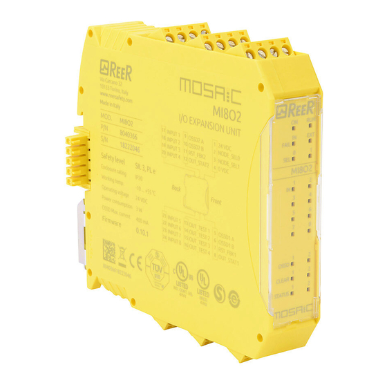
Page 31: Mi8O2 (Figure 11)
MODULAR SAFETY INTEGRATED CONTROLLER MOSAIC MI8O2 (Figure 11) IN FAIL EXT FAIL IN1÷8 OSSD1/2 CLEAR1/2 STATUS1/2 MEANING ORANGE GREEN YELLOW RED/GREEN YELLOW YELLOW FAIL Power on - initial TEST Table 16 - Opening Screen IN FAIL EXT FAIL IN1÷8 OSSD1/2 CLEAR1/2 STATUS1/2 MEANING... -
Page 32: Mi8 (Figure 12)
MODULAR SAFETY INTEGRATED CONTROLLER MOSAIC MI8 (Figure 12) MEANING IN FAIL EXT FAIL IN1÷8 GREEN ORANGE YELLOW Power on - initial TEST FAIL Table 18 - Opening Screen MEANING IN FAIL EXT FAIL IN1÷8 GREEN ORANGE YELLOW if the unit is waiting for the first INPUT condition communication from the MASTER FLASHES... -
Page 33: Mi12T8 (Figure 14)
MODULAR SAFETY INTEGRATED CONTROLLER MOSAIC MI12T8 (Figure 14) MEANING IN FAIL EXT FAIL IN1÷12 GREEN ORANGE YELLOW Power on - initial TEST Table 20 - Opening Screen MEANING IN FAIL EXT FAIL IN1÷12 GREEN ORANGE YELLOW if the unit is waiting for the first INPUT condition communication from the MASTER FLASHES... -
Page 34: Mi16 (Figure 14)
MODULAR SAFETY INTEGRATED CONTROLLER MOSAIC MI16 (Figure 14) MEANING IN FAIL EXT FAIL IN1÷16 GREEN ORANGE YELLOW Power on - initial TEST FAIL Table 22 - Opening Screen MEANING IN FAIL EXT FAIL IN1÷16 GREEN ORANGE YELLOW if the unit is waiting for the first INPUT condition communication from the MASTER FLASHES... -
Page 35: Mo2 (Figure 15)
MODULAR SAFETY INTEGRATED CONTROLLER MOSAIC MO2 (Figure 15) MEANING IN FAIL EXT FAIL OSDD1/2 CLEAR1/2 STATUS1/2 GREEN ORANGE RED/GREEN YELLOW YELLOW Power on - initial TEST FAIL Table 24 - Opening screen MEANING IN FAIL EXT FAIL OSSD1/2 CLEAR1/2 STATUS1/2 GREEN ORANGE RED/GREEN... -
Page 36: Mo4 (Figure 16)
MODULAR SAFETY INTEGRATED CONTROLLER MOSAIC MO4 (Figure 16) MEANING IN FAIL EXT FAIL OSDD1/4 CLEAR1/4 STATUS1/4 GREEN ORANGE RED/GREEN YELLOW YELLOW Power on - initial TEST FAIL Table 26 - Opening screen MEANING IN FAIL EXT FAIL OSDD1/4 CLEAR1/4 STATUS1/4 GREEN ORANGE RED/GREEN... -
Page 37: Mr2 (Figure 17) / Mr4 (Figure 18)
MODULAR SAFETY INTEGRATED CONTROLLER MOSAIC MR2 (Figure 17) / MR4 (Figure 18) OSSD1 MEANING GREEN NORMAL OPERATION ON with output activated Table 28 - MR2 - Dynamic screen MEANING OSSD1 OSSD2 GREEN GREEN NORMAL OPERATION ON with output activated Table 29 - MR4 - Dynamic screen OSSD OSSD Figure... -
Page 38: Troubleshooting
MOSAIC again. Configuration 5 flashes • If the problem error flashes flashes flashes flashes persists return the M1 to ReeR to be repaired • Check the OSSD1/2 4 flashes connections OSSD output (only the LED • If the problem error... -
Page 39: Mi8O2 (Figure 20)
OSSD1/2 CLEAR1/2 STATUS1/2 MEANING REMEDY ORANGE GREEN YELLOW RED/GREEN YELLOW YELLOW 2 or 3 Return the unit to ReeR Internal fault flashes to be repaired • Firmware version not FAIL compatible with M1, Compatibility error 5 flashes flashes flashes flashes... -
Page 40: Mi8 (Figure 21)
CLEAR1/2 STATUS1/2 MEANING REMEDY GREEN ORANGE YELLOW RED/GREEN YELLOW YELLOW FAIL 2 or 3 Return the unit to ReeR to Internal fault flashes be repaired • Firmware version not compatible with M1, Compatibility error flashes flashes flashes flashes flashes return to ReeR for FW upgrade. -
Page 41: Mi12T8 (Figure 22)
IN1÷12 OSSD1/2 CLEAR1/2 STATUS1/2 REMEDY ORANGE GREEN YELLOW RED/GREEN YELLOW YELLOW 2 or 3 Return the unit to ReeR to Internal fault flashes be repaired • Firmware version not compatible with M1, Compatibility error flashes flashes flashes flashes flashes return to ReeR for FW upgrade. -
Page 42: Mi16 (Figure 23 - Mi16)
CLEAR1/2 STATUS1/2 MEANING REMEDY ORANGE GREEN YELLOW RED/GREEN YELLOW YELLOW FAIL 2 or 3 Return the unit to ReeR to Internal fault flashes be repaired • Firmware version not compatible with M1, Compatibility error flashes flashes flashes flashes flashes return to ReeR for FW upgrade. -
Page 43: Mo2 / Mo4 (Figure 24)
IN FAIL EXT FAIL OSSD1/4 CLEAR1/2 STATUS1/2 REMEDY ORANGE GREEN RED/GREEN YELLOW YELLOW 2 or 3 Return the unit to ReeR Internal fault flashes to be repaired • Firmware version not FAIL FAIL compatible with M1, Compatibility error flashes flashes flashes... -
Page 44: Mosaic Safety Designer Software
MODULAR SAFETY INTEGRATED CONTROLLER MOSAIC MOSAIC SAFETY DESIGNER SOFTWARE The "MOSAIC SAFETY DESIGNER" application software can be used to configure a logic diagram of the connections between the MOSAIC (Master + expansions) and the components of the system being developed. The MOSAIC and its SLAVE units will thus monitor and control the connected safety components. -
Page 45: Fundamentals
MODULAR SAFETY INTEGRATED CONTROLLER MOSAIC Fundamentals Once the MSD has been correctly installed it creates an icon on the desktop. To launch the program: double-click on this icon. => The opening screen shown below is displayed: Figure 25 You are now ready to create your project. 8540780 •... -
Page 46: Standard Tool Bar
MODULAR SAFETY INTEGRATED CONTROLLER MOSAIC Standard tool bar The standard tool bar is shown in Figure 26. The meanings of the icons are listed below: Figure 26 1 -> CREATE A NEW PROJECT 2 -> CHANGE CONFIGURATION (composition of different modules) 3 ->... -
Page 47: Textual Tool Bar
MODULAR SAFETY INTEGRATED CONTROLLER MOSAIC Textual tool bar Optionally the textual tool bar shown below is also available (drop down). Figure 27 Create a new project (configure the MOSAIC system) Select icon CREATE (Figure 26) from the standard tool bar to start a new project. The user authentication window is displayed (Figure 28). -
Page 48: Edit Configuration (Composition Of The Various Modules)
MODULAR SAFETY INTEGRATED CONTROLLER MOSAIC EDIT CONFIGURATION (composition of the various modules) The change of the system composition is obtained with the icon The configuration window is showed again (Figure 26). Change user parameters The change of user parameters is obtained with the icon The dialog user identification request appears (Figure 30). -
Page 49: Objects - Operator - Configuration Tool Bars
MODULAR SAFETY INTEGRATED CONTROLLER MOSAIC OBJECTS - OPERATOR - CONFIGURATION tool bars Four large tool windows are displayed to the left and right of the main window (shown in Figure 31): Figure 31 1 > OBJECT TOOL WINDOW This contains the various function blocks that will make up your project; these blocks are divided into 3 different types: - physical - inputs... -
Page 50: Creating The Diagram (Figure 16)
MODULAR SAFETY INTEGRATED CONTROLLER MOSAIC Creating the diagram (Figure 16) Once you have selected your system composition, you are ready to configure the project. The logic diagram is created using a DRAG&DROP function: • Select the objects as required from the windows described previously (each single object is described in detail in the following sections) and drag it into the design area. -
Page 51: Example Of A Project
MODULAR SAFETY INTEGRATED CONTROLLER MOSAIC Example of a project Figure 33 shows an example of a project in which the M1 unit only is connected to two safety blocks (E-GATE and E-STOP). The M1 inputs (1,2,3) for connecting the contacts of the safety components are shown on the left, in yellow. -
Page 52: Project Report
MODULAR SAFETY INTEGRATED CONTROLLER MOSAIC Project report Print of the System composition with properties of each block. (Icon on the standard toolbar). This definition of PL and of the other related parameters as set forth in ISO 13849-1 only refers to the functions implemented in the Mosaic system by the MSD configuration software, assuming configuration has been performed correctly. -
Page 53: Connect To Mosaic
MODULAR SAFETY INTEGRATED CONTROLLER MOSAIC Connect to Mosaic After connecting M1 to the PC via CSU cable (USB) use the icon for the connection. A window appears to request the password. Enter the password (see "Password protection"). Figure 34 Sending the configuration to the MOSAIC To send the saved configuration from a PC to M1 use the icon on the standard toolbar and wait the execution. -
Page 54: System Composition
MODULAR SAFETY INTEGRATED CONTROLLER MOSAIC System composition The check of the actual composition of the MOSAIC system is obtained using the icon . (Password Required: level 1). A pop-up window will appear with: - Connected modules; - Firmware version of each module; - Node number (physical address) of each module. -
Page 55: Monitor (I/O Status In Real Time - Textual)
MODULAR SAFETY INTEGRATED CONTROLLER MOSAIC MONITOR (I/O status in real time - textual) To activate the monitor use the icon . (Password Required: level 1). A pop-up window will appear (in real time) with: - Status of the inputs (when the object has two or more input connections to Mosaic, the MONITOR will show as active only the first), see the example in figure;... -
Page 56: Password Protection
When a new project is UPLOADED the level 2 password could be changed. Should you forget either of these passwords, please contact ReeR which will provide an unlock file (when the unlock file is saved in the right directory the icon will appear on the toolbar). -
Page 57: Testing The System
MODULAR SAFETY INTEGRATED CONTROLLER MOSAIC TESTING the system After validating and uploading the project to the M1 and connecting all the safety devices, you must test the system to verify its correct operation. This is done by forcing a change of status for each safety device connected to the MOSAIC to check that the status of the outputs actually changes. -
Page 58: Object Function Blocks
MODULAR SAFETY INTEGRATED CONTROLLER MOSAIC OBJECT FUNCTION BLOCKS OUTPUT OBJECTS OSSD (safety outputs) The OSSD semiconductor safety outputs require no maintenance, Output1 and Output2 supply 24Vdc if the input is 1 (TRUE), whereas they supply 0Vdc if the input is 0 (FALSE). Each pair OSSD... -
Page 59: Input Objects
MODULAR SAFETY INTEGRATED CONTROLLER MOSAIC INPUT OBJECTS E-STOP (emergency stop) E-STOP function block verifies an emergency stop device inputs status. If the emergency stop button has been pressed the output is 0 (FALSE). If not the output is 1 (TRUE). Parameters Input type: - Single NC –... -
Page 60: E-Gate (Safety Gate Device)
MODULAR SAFETY INTEGRATED CONTROLLER MOSAIC a complete function test and enable the output. This test is only requested at machine start-up (when the unit is switched on). Filter (ms): This is used to filter the signals coming from the emergency stop. The filter can be configured to between 3 and 250 ms and eliminates any bouncing on the contacts. -
Page 61: Enable (Enable Key)
MODULAR SAFETY INTEGRATED CONTROLLER MOSAIC WARNING: If the Manual Reset is active, a consecutive Input have to be used. Example : Input 1 and Input 2 are used for the fuctional block, then Input 3 have to be used for the Reset Input. Output test: This is used to select which test output signals are to be sent to the component contacts. -
Page 62: Espe (Optoelectronic Safety Light Curtain / Laser Scanner)
MODULAR SAFETY INTEGRATED CONTROLLER MOSAIC Output test: This is used to select which test output signals are to be sent to the component contacts. This additional control permits detection and management of any short-circuits between the lines. To enable this control, the test output signals must be configured (amongst those available). - Page 63 MODULAR SAFETY INTEGRATED CONTROLLER MOSAIC Otherwise, enabling of the output directly follows the input conditions. There are two types of reset: Manual and Monitored. When Manual is selected the system only verifies the signal's transition from 0 to 1. If Monitored is selected the double transition from 0 to 1 and then back to 0 is verified.
-
Page 64: Footswitch (Safety Pedal)
MODULAR SAFETY INTEGRATED CONTROLLER MOSAIC FOOTSWITCH (safety pedal) The FOOTSWITCH function block verifies the status of the inputs of a safety pedal device. If the pedal is not pressed the output is 0 (FALSE). Otherwise the output is 1 (TRUE). Parameters Input type: - Single NC –... -
Page 65: Mod-Sel (Safety Selector)
MODULAR SAFETY INTEGRATED CONTROLLER MOSAIC Filter (ms): This is used to filter the signals coming from the external contacts. The filter can be configured to between 3 and 250 ms and eliminates any bouncing on the contacts. The length of the filter affects the calculation of the unit's total response time. With Contemporaneity: If selected this activates the test to verify concurrent switching of the signals coming from the external contacts. - Page 66 MODULAR SAFETY INTEGRATED CONTROLLER MOSAIC Monitored. When Manual is selected the system only verifies the signal's transition from 0 to 1. If Monitored is selected the double transition from 0 to 1 and then back to 0 is verified. WARNING: If the Manual Reset is active, a consecutive Input have to be used. Example : Input 1 is used for the fuctional block, then Input 2 have to be used for the Reset Input.
-
Page 67: Two-Hand (Bimanual Control)
MODULAR SAFETY INTEGRATED CONTROLLER MOSAIC TWO-HAND (bimanual control) The TWO HAND function block verifies the status of the inputs of a two hand control switch. Only if both the press-buttons are pressed within 500 msec the output is 1 (TRUE). Otherwise the output is 0 (FALSE). Input type: - Double NO –... - Page 68 MODULAR SAFETY INTEGRATED CONTROLLER MOSAIC WARNING: If the Manual Reset is active, a consecutive Input have to be used. Example : Input 1 is used for the fuctional block, then Input 2 have to be used for the Reset Input. Output test: This is used to select which test output signals are to be sent to the sensor.
-
Page 69: S-Mat (Safety Mat)
MODULAR SAFETY INTEGRATED CONTROLLER MOSAIC S-MAT (safety mat) The S-MAT function block verifies the status of the inputs of a safety mat. If a person stands on the mat the output is 0 (FALSE). Otherwise, with the mat clear, the output is 1 (TRUE). Parameters Manual reset: If selected this enables the request... -
Page 70: Switch
MODULAR SAFETY INTEGRATED CONTROLLER MOSAIC Item description: This allows a description of the component's function to be entered. The text is displayed in the top part of the symbol. SWITCH SWITCH function block verifies the input status pushbutton switch (NOT SAFETY SWITCHES). -
Page 71: Enabling Grip Switch
MODULAR SAFETY INTEGRATED CONTROLLER MOSAIC ENABLING GRIP SWITCH The ENABLING GRIP functional block checks the status of the In inputs of an enabling grip. If this is not gripped (position 1) or is gripped completely (position 3), the OUTPUT will be 0 (FALSE). If it is gripped to middle position (position 2), the OUTPUT will be 1 (TRUE). -
Page 72: Testable Safety Device
MODULAR SAFETY INTEGRATED CONTROLLER MOSAIC Table mode 1 (device 2NO + 1NC) POSITION 1: enabling grip fully released POSITION 2: enabling grip pressed to middle position POSITION 3: enabling grip fully pressed Position Input Input (only with 1NO+1NC) Enable Error Out: If selected reports a fault detected by the function block. Item description: Permits insertion of a descriptive text of the function of the component. - Page 73 MODULAR SAFETY INTEGRATED CONTROLLER MOSAIC WARNING: if Reset is enabled, the input consecutive to those used by the functional block must be used. For example: If inputs 1 and 2 are used for the functional block, input 3 must be used for Reset. Power-on test: If selected, enables the power-on test of the device.
-
Page 74: Solid State Device
MODULAR SAFETY INTEGRATED CONTROLLER MOSAIC SOLID STATE DEVICE The SOLID STATE DEVICE functional block checks the status of the Inx inputs. If the inputs are at 24VDC, the Output will be 1 (TRUE), otherwise the OUTPUT will be 0 (FALSE). Parameters Manual Reset: If selected, enables the reset request after each occupation of the area protected by the... -
Page 75: Fieldbus Input
MODULAR SAFETY INTEGRATED CONTROLLER MOSAIC FIELDBUS INPUT Element that permits insertion of a non-safety input whose status is modified via the fieldbus. Up to 8 virtual inputs can be inserted and the bit on which status is to be modified must be selected for each. -
Page 76: Operator Function Blocks
MODULAR SAFETY INTEGRATED CONTROLLER MOSAIC OPERATOR FUNCTION BLOCKS All the input of these operators could be inverted (logical NOT). It could be done clicking with the right mouse key on the input to be inverted. A little circle will be showed on the inverted input. -
Page 77: Not
MODULAR SAFETY INTEGRATED CONTROLLER MOSAIC Logical NOT inverts the logical status of the input. Logical OR returns an output of 1 (TRUE) if at least one of the inputs is 1 (TRUE). Parameters Number of inputs: this is used to set between 2 and 8 inputs. Logical NOR returns an output of 0 (FALSE) if at least one of the inputs is 1 (TRUE). -
Page 78: Xor
MODULAR SAFETY INTEGRATED CONTROLLER MOSAIC Logical XOR returns an output 0 (FALSE) if the input's number at 1 (TRUE) is even or the inputs are all 0 (FALSE). Parameters Number of inputs: this is used to set between 2 and 8 inputs. XNOR Logical XNOR returns an output 1 (TRUE) if the input's number at 1 (TRUE) is even or the... -
Page 79: Memory Operators
MODULAR SAFETY INTEGRATED CONTROLLER MOSAIC MEMORY OPERATORS MEMORY operators can be used if you decide to save any data (TRUE or FALSE) from other project components. Status changes are performed according to the truth tables shown for each operator. D FLIP FLOP (max number = 16) The D FLIP FLOP operator saves the previously set status on output Q according to the following truth table. -
Page 80: Sr Flip Flop
MODULAR SAFETY INTEGRATED CONTROLLER MOSAIC SR FLIP FLOP SR FLIP FLOP operator brings output Q at 1 with Set, 0 with Reset. See the following truth table. SET RESET Keep memory USER RESTART MANUAL (max number = 16 with RESTART MONITORED) The USER RESTART MANUAL operator saves the restart signal according to the following truth table. -
Page 81: Counter Operators
MODULAR SAFETY INTEGRATED CONTROLLER MOSAIC COUNTER OPERATORS COUNTER operator is a pulse counter that sets output Q to 1 (TRUE) as soon as the desired count is reached. COUNTER (max number = 16). The operator COUNTER is a pulse counter. There are 3 operationg modes: 1) AUTOMATIC 2) MANUAL... -
Page 82: Monostable
MODULAR SAFETY INTEGRATED CONTROLLER MOSAIC MONOSTABLE The MONOSTABILE operator generates a level 1 (TRUE) output activated by the rising edge of the input and remains in this condition for the set time. Parameters Time: The delay can be set to between 10 ms and 1093.3 s. -
Page 83: Passing Make Contact
MODULAR SAFETY INTEGRATED CONTROLLER MOSAIC PASSING MAKE CONTACT In the PASSING MAKE CONTACT operator the output follows the signal on the input. However, if this is 1 (TRUE) for longer than the set time, the output changes to 0 (FALSE). When there is an input falling edge, the timer is cleared. -
Page 84: Delay
MODULAR SAFETY INTEGRATED CONTROLLER MOSAIC DELAY DELAY operator applies a delay to a signal by setting the output to 1 (TRUE) after the set time, against a change in the level of the input signal. Parameters Time: The delay can be set to between 10 ms and 1093.3 s Rising edge: If selected, the delay starts on the input signal's rising edge at the end of which the output changes to 1 (TRUE) if the input is 1 (TRUE) where it remains for as long... -
Page 85: Muting Operators (Max Number = 4)
MODULAR SAFETY INTEGRATED CONTROLLER MOSAIC MUTING OPERATORS (max number = 4) "Concurrent" MUTING The MUTING operator with "Concurrent" logic performs muting of the input signal through sensor inputs S1, S2, S3 and S4. Preliminary condition: The Muting cycle can only start if all the sensors are 0 (FALSE) and inputs are 1 (TRUE) (barrier free). -
Page 86: Muting "L
MODULAR SAFETY INTEGRATED CONTROLLER MOSAIC Blind Time: Only with Muting Close=Curtain, blind time is enabled if you know that after the complete transition of the pallet (muting cycle close) some protruding objects could still occupy the light curtain and send the input to 0 (FALSE). During blind time the input remains 1 (TRUE). -
Page 87: Sequential" Muting
MODULAR SAFETY INTEGRATED CONTROLLER MOSAIC "Sequential" MUTING The MUTING operator with "Sequential" logic performs muting of the input signal through sensor inputs S1, S2, S3 and S4. Preliminary condition: The Muting cycle can only start if all the sensors are 0 (FALSE) and the inputs are 1 (TRUE) (barrier free). -
Page 88: Muting "T
MODULAR SAFETY INTEGRATED CONTROLLER MOSAIC Blind Time: Only with Muting Close=Curtain, blind time is enabled if you know that after the complete transition of the pallet (muting cycle close) some protruding objects could still occupy the light curtain and send the input to 0 (FALSE). During blind time the input remains 1 (TRUE). -
Page 89: Muting Override (Max Number = 16)
MODULAR SAFETY INTEGRATED CONTROLLER MOSAIC MUTING OVERRIDE (max number = 16) The operator permits override of the directly connected Muting Input. Override can be activated only if Muting is not active (INPUT=0) and at least one Muting sensor is occupied (or the light curtain is occupied). Override ends when the light curtain and sensors are cleared and the Output switches to logical "0"... -
Page 90: Special Applications
MODULAR SAFETY INTEGRATED CONTROLLER MOSAIC SPECIAL APPLICATIONS Output delay with manual If you need to have two OSSD output with one of them delayed (in MANUAL mode) use the following scheme: Figure 42 - Two outputs with one delayed (in MANUAL mode) Whereas the operating mode of the logical DELAY (see DELAY paragraph) the application must be the following: - The two outputs have to be programmed with RESET TYPE manual (monitored) -
Page 91: Accessories And Spare Parts
MODULAR SAFETY INTEGRATED CONTROLLER MOSAIC ACCESSORIES AND SPARE PARTS MODEL DESCRIPTION CODE MOSAIC main unit (8 inputs / 2 double OSSD ) 1100000 MI8O2 MOSAIC I/O expansion unit (8 inputs / 2 double OSSD) 1100010 MOSAIC input expansion unit (8 inputs) 1100020 MI16 MOSAIC input expansion unit (16 inputs) -
Page 92: Warranty
MODULAR SAFETY INTEGRATED CONTROLLER MOSAIC WARRANTY ReeR warrants that all of its MOSAIC units shall be free from defects in material or workmanship for a period of 12 (twelve) months from the date of shipment. This warranty applies to the products under normal conditions of use. -
Page 93: 8540780 • 25Th June 2012 • Rev.15
MODULAR SAFETY INTEGRATED CONTROLLER MOSAIC ReeR S.p.A. 32 via Carcano 10153 Torino Italia Tel. +39/0112482215 r.a. Fax +39/011859867 Internet: www.reer.it e-mail: info@reer.it 8540780 • 25th June 2012 • Rev.15...
Need help?
Do you have a question about the MOSAIC Master M1 and is the answer not in the manual?
Questions and answers