Sign In
Upload
Manuals
Brands
Mitsubishi Electric Manuals
Adapter
FX-485ADP
Mitsubishi Electric FX-485ADP Manuals
Manuals and User Guides for Mitsubishi Electric FX-485ADP. We have
2
Mitsubishi Electric FX-485ADP manuals available for free PDF download: User Manual
Mitsubishi Electric FX-485ADP User Manual (818 pages)
MELSEC-F FX SERIES PROGRAMMABLE CONTROLLERS Data Communication Edition
Brand:
Mitsubishi Electric
| Category:
Controller
| Size: 22.75 MB
Table of Contents
7
Table of Contents
29
Introduction
31
Outline and Features of Communication Types
34
Ethernet Communication
35
N:N Network
36
Parallel Link
37
Computer Link
38
Inverter Communication
39
Non-Protocol Communication
40
MODBUS Communication
41
Programming Communication
44
Remote Maintenance
45
CC-Link/Lt Network
46
Anywireaslink
47
As-I System
48
Internet Mail Sending
49
Short Mail Sending
51
Communication Types and Communication Equipment
52
Communication Equipment Applicability Map
64
Fx 1Nc
66
FX 0N Plcs
68
Combination of Communication Equipment (Block Diagram)
71
232Adp *1
71
Fx -485Adp
85
485Adp
88
Fx 1Nc
88
16Ccl
88
Fx 2N -32Ccl *4
88
Fx 2N -32Asi
93
Outline of Communication Setting in the FX Series
95
Communication Setting Using Parameter Method (GX Works2)
96
Correspondence Between Parameter Setting and Each Communication Type
97
Communication Setting in Parameter Method (FXGP/WIN)
99
Correspondence Between Parameter Setting and Each Communication Type
100
Extension of Ports (For FX 3G , FX 3GC , FX 3U , FX 3UC )
103
Limitation When Ch1 and Ch2 Are Used at the Same Time
104
Version Number
105
Checking the Front of the Product
106
Introduction of Manuals (Type, Reading Method and Acquisition Method)
107
Introduction of Related Manuals
110
Communication Equipment (Option)
112
Related Options for Communication
113
Abbreviations, Generic Names and Terms Used in This Manual
121
Outline
122
Procedures before Operation
123
Communication Type Applicability in PLC
124
Programming Tool Applicability
126
For Non-Applicable Versions (Setting an Alternative Model)
127
Specifications
128
Link Specifications
129
Link Time
130
System Configuration and Equipment Selection
131
Applicable FX PLC and Communication Equipment
136
Wiring
137
Selecting Cables and Terminal Resistors
138
Connecting Cables
140
Connecting Terminal Resistors
141
Connection Diagram
143
Grounding
144
Communication Setting (Initialization) in FX Programmable Controller
145
Communication Setting Using Parameter Method (GX Works2)
146
Communication Settings Using Parameter Method (FXGP/WIN)
147
Test Run (Communication Test)
149
Creating Programs for the Communication Testing
150
Creating a Program for Each Slave Station
151
Creating Programs
153
Creating Programs for Master Station (Station No. 0)
156
Creating Programs for Slave Station (Station No. "N")
158
Cautions On Program Creation
159
Practical Program Examples
160
Setting Contents
162
Setting Program for Slave Station (No. 1)
164
Setting Program for Slave Station (No. 2)
166
Troubleshooting
168
Checking Setting Contents and Errors
169
Checking Data Transfer Sequence Errors
172
Related Data
178
Details of Related Devices
179
Data Transfer Sequence Error [M8138 to M8190] [M504 to M511]
180
Corresponding Station Number Settings Status [D8173]
181
Slave Station Quantity Setting [D8177]
182
Number of Retries [D8179]
183
Maximum Link Scan Time [D8202] [D202]
184
Data Transfer Error Code [D8211 to D8218] [D211 to D218]
185
Operation Mode Display [D8419 and D8439]
189
Outline
190
Procedures before Operation
191
Communication Type Applicability in PLC
192
Programming Tool Applicability
194
For Non-Applicable Versions (Setting an Alternative Model)
195
Specifications
196
Link Specifications
197
Link Device Numbers and Number of Points
199
System Configuration and Selection
200
Configuration of Each Group
204
Applicable FX PLC and Communication Equipment
210
Wiring
211
Selecting Cables and Terminal Resistors
212
Connecting Cables
213
Optical Fiber Cable
214
Connecting Terminal Resistors
215
Connection Diagram
217
Grounding
218
Communication Setting (Initialization) in FX Programmable Controller
219
Communication Setting Using Parameter Method (GX Works2)
220
Communication Setting Using Parameter Method (FXGP/WIN)
221
Test Run (Communication Test)
222
Creating Programs for the Communication Test
224
Creating Programs
226
Creating Programs for Master Station
227
Creating Programs for Slave Station
228
High Speed Parallel Link Mode
230
Creating Programs for Master Station
231
Creating Programs for Slave Station
232
Cautions On Program Creation
233
Practical Program Examples
234
Program for Master Station
235
Troubleshooting
237
Checking Absence/Presence of Errors
238
Related Data
239
Details of Related Devices
240
Parallel Link ON [M8072]
241
Serial Communication Error Code [D8063 and D8438]
245
Outline
246
Procedures before Operation
247
Communication Type Applicability in PLC
248
Programming Tool Applicability
250
For Non-Applicable Versions (Setting an Alternative Model)
251
Specifications
252
Link Specifications
253
Applicable Device Ranges
255
Link Time
256
System Configuration and Equipment Selection
257
Applicable FX PLC and Communication Equipment
263
For Communication in Accordance with RS-485
269
Wiring
270
Wiring Procedure
271
Selecting Connection Method
272
Selecting Cables and Terminal Resistors (RS-485)
273
Connecting Cables
275
Connecting Terminal Resistors
276
Connection Diagram for RS-232C
277
Connection Diagram for RS-485 and RS-422
279
Two-Pair Wiring
281
Grounding
282
Communication Setting in FX Programmable Controller
283
Communication Setting Using Parameter Method (GX Works2)
285
Communication Settings Using Parameter Method (FXGP/WIN)
287
Control Procedures and Setting Methods
288
Important Points in Computer Link
289
How to Understand Control Procedure
290
Control Procedure Format 1
291
Control Procedure Format 4
292
Contents of Set Items in Each Control Procedure (Protocol)
295
Time-Out Time Setting
296
Transfer Sequence Time Chart and Communication Time
297
Transfer Time in Transfer Sequence
298
Transfer Data in Character Area
299
When Word Device Memory Is Read or Written
300
Commands
301
BR Command [Reads Device Memory in 1-Bit Units]
302
WR Command [Reads Device Memory in 1-Word Units]
304
QR Command [Reads Device Memory in 1-Word Units]
306
BW Command [Writes Device Memory in 1-Bit Units]
307
WW Command [Writes Device Memory in 1-Word Units]
309
QW Command [Writes Device Memory in 1-Word Units]
311
BT Command [Tests Device Memory in 1-Bit Units (By Writing Arbitrarily)]
312
WT Command [Tests Device Memory in 1-Word Units (By Writing Arbitrarily)]
314
QT Command [Tests Device Memory in 1-Word Units (By Writing Arbitrarily)]
315
RR/RS Command [Remotely Sets PLC to RUN/STOP Mode]
316
Remote Control Specification Method and Specification Examples
317
PC Command [Reads PLC Model Name]
319
GW Command [Offers Global Function]
320
On-Demand Function
322
Control Procedures in On-Demand Function
324
On-Demand Function Specification Method and Specification Examples
327
TT Command [Loop-Back Test]
328
Troubleshooting
330
Checking Error Codes
331
Error Codes in PLC
332
Related Data
334
Details of Related Devices
335
On-Demand Error Flag [M8128 and M8428]
336
Communication Format Setting [D8120 and D8420]
337
Station Number Settings [D8121 and D8421]
338
On-Demand Data Head Device Number Specification [D8127 and D8427]
339
Time-Out Time Setting [D8129 and D8429]
340
Communication Setting Method Using Sequence Program
341
ASCII Code Table
345
Outline
346
Procedures before Operation
347
Communication Type Applicability in PLC
348
Programming Tool Applicability
349
For Non-Applicable Versions (Setting an Alternative Model)
350
Specifications
351
Link Specifications
352
Execution Times in Inverter Communication Instructions
354
Calculation Method
356
Calculation Example
358
System Configuration and Selection
360
Applicable FX PLC and Communication Equipment
365
Wiring
366
Wiring Procedure
367
Selecting Cables and Connection Devices
368
A500, F500 and V500 Series (FR-A5NR)
369
F800, A800, F700 and A700 Series (Built-In RS-485 Terminal)
370
E700 Series (FR-E7TR)
371
Connection Cables
372
Connecting Cables
373
Connection Devices (RJ45 Connector and Distributor)
374
Connecting Terminal Resistors
375
Wiring a Shielding Wire (Class-D Grounding)
376
Connector in Inverter
378
Connection Diagram
380
For A500, F500 and V500 Series (FR-A5NR)
381
For E700 Series (PU Connector)
385
For E700 Series (FR-E7TR)
388
For F800, A800, F700 and A700 Series (Built-In RS-485 Terminal)
389
Grounding
390
Communication Setting in Inverter
392
S500 Series (When Connected to RS-485 Port)
393
Parameter Setting Method (Reference)
395
E500 Series (When Connected to PU Port)
396
Parameter Setting Method (Reference)
398
V500, F500 and A500 Series (Connection to PU Port)
399
Parameter Setting Method (Reference)
401
V500, F500 and A500 Series (Connection to FR-A5NR)
402
E700, D700 Series (When PU Port, FR-E7TR Is Connected)
404
Parameter Setting Method (Reference)
406
F700 and A700 Series (When Built-In RS-485 Terminal Is Connected)
407
Parameter Setting Method (Reference)
409
F800 and A800 Series (When Built-In RS-485 Terminal Is Connected)
410
Parameter Setting Method (Reference)
411
Cautions On Setting
412
Communication Setting in FX Programmable Controller
413
Communication Setting Using Parameter Method (GX Works2)
415
Communication Setting Using Parameter Method (FXGP/WIN)
417
Creating Programs (FX 2N , FX 2NC )
418
Common Items in Inverter Communication Instructions
420
Instruction Completion and Error Flag Operation
422
Cautions On Programming
423
Inverter Operation Monitoring Instruction (PlcInverter) [EXTR K10]
424
Inverter Operation Control Instruction (PlcInverter) [EXTR K11]
425
Inverter Parameter Reading Instruction (PlcInverter) [EXTR K12]
426
Inverter Parameter Writing Instruction (PlcInverter) [EXTR K13]
427
Second Parameter Specification Codes
428
A500 Series
429
Practical Program Examples (FX 2N , FX 2NC )
430
Program Example
433
Practical Example 2
434
Program Example
438
Creating Programs (FX 3S , FX 3G , FX 3GC , FX 3U , FX 3UC )
439
Contents of Related Devices
440
Common Items in Inverter Communication Instructions
442
Instruction Completion and Error Flag Operation
444
Cautions On Programming
446
Inverter Operation Monitoring Instruction (PlcInverter) [FNC270 / IVCK]
447
Inverter Operation Control Instruction (PlcInverter) [FNC271 / IVDR]
448
Inverter Parameter Reading (PlcInverter) [FNC272 / IVRD]
450
Inverter Parameter Writing (PlcInverter) [FNC273 / IVWR]
451
Inverter Parameter Batch Writing (PlcInverter) [FNC274 / IVBWR]
452
Controls Operations and Monitors Operations of an Inverter with a Single Command(PlcInverter)[Fnc275 / IVMC]
453
Applicable Inverters
454
Second Parameter Specification Codes
455
A500 Series
456
F500 Series
457
A700 Series
458
E700 and D700 Series
459
F800 Series
460
A800 Series
461
Practical Program Examples (FX 3S , FX 3G , FX 3GC , FX 3U , FX 3UC )
462
Program Example
467
Practical Example 2
468
Program Example
476
Troubleshooting
477
Checking Inverter Operation Status
478
Checking Absence/Presence of Errors
481
Related Data
482
Details of Related Devices (FX 2N , FX 2NC )
483
Communication Error Latch [M8157]
484
Error Code [D8156]
485
Error Occurrence Step Number Latch [D8157]
486
Related Device List (FX 3S , FX 3G , FX 3GC , FX 3U , FX 3UC )
487
Details of Related Devices (FX 3S , FX 3G , FX 3GC , FX 3U , FX 3UC )
488
Inverter Communication Error [M8152, M8153, M8157 and M8158]
489
Step Number of Instruction Using Communication Port [D8151 and D8156]
492
Inverter Communication Error Occurrence Step [D8153 and D8158]
493
FREQROL Inverter Parameter List
515
Parameters in F700, A700, E700 and D700 Series
532
Parameters in F800 and A800 Series
550
Communication Parameters
553
Outline
557
Procedures before Operation
558
Communication Type Applicability in PLC
559
Programming Tool Applicability
561
For Non-Applicable Versions (Setting an Alternative Model)
562
Specifications
563
Data Communication Specifications
564
Number of Transfer Data
565
System Configuration and Selection
566
Applicable FX PLC and Communication Equipment
572
For Communication in Accordance with RS-485
577
Wiring
578
Selecting Cables and Terminal Resistors
579
BASE-T Cable
580
Connecting Cables
582
Connecting Terminal Resistors
583
Connection Diagram
585
Wiring for Communication in Accordance with RS-485
589
Grounding
590
Communication Setting in FX Programmable Controller
591
Communication Setting Using Parameter Method (GX Works2)
593
Communication Setting Using Parameter Method (FXGP/WIN)
595
Creating Programs (RS Instruction)
596
How to Use RS Instruction
597
Function and Operation
598
Send/Receive Data and Amount of Data
600
Operation When Data Is Sent
602
Operation of Control Line
606
Important Points in Creating Programs
607
Practical Program Example (RS Instruction)
609
Creating Programs (RS2 Instruction)
612
How to Use RS2 Instruction
613
Applicable Frames
615
Function and Operation
616
Send/Receive Data and Amount of Data
618
Operation When Data Is Sent
621
Sum Check Code
622
Operation of Control Line
625
Important Points in Creating Programs
626
Practical Program Example (RS2 Instruction)
628
When Combined with Another Communication
629
When Combined with Programming Communication
631
When Combined with Computer Link Communication
632
When Combined with Programming Communication
633
Using RS2 Instruction and Computer Link Communication Together
634
Communication Setting Method Using Sequence Program
636
Communication Setting for RS2 Instruction
637
Troubleshooting
638
Checking Sequence Program
639
Checking the Absence/Presence of Errors
640
Related Data
641
Details of Related Devices (RS Instruction)
642
Receiving Complete Flag [M8123]
643
Serial Communication Error Code [D8063]
644
Communication Format Setting [D8120]
645
Amount of Data Already Received [D8123]
646
Operation Mode Display [D8419]
647
Details of Related Devices (RS2 Instruction)
648
Sending Wait Flag [M8371, M8401 and M8421]
649
Carrier Detection Flag [M8404 and M8424]
650
Serial Communication Error Code [D8062, D8063 and D8438]
651
Communication Format Setting [D8370, D8400 and D8420]
652
Amount of Remaining Send Data [D8372, D8402 and D8422]
653
Header [D8380, D8381, D8410, D8411, D8430 and D8431]
654
Receiving Sum (Receive Data) [D8384, D8414 and D8434]
655
Operation Mode Display [D8389, D8419 and D8439]
656
ASCII Code Table
659
Outline
660
Procedures before Operation
661
Communication Type Applicability in PLC
662
Programming Tool Applicability
663
For Non-Applicable Versions (Setting an Alternative Model)
664
Specification
665
System Configuration and Selection
666
Connection to PLC
668
Wiring
669
Connection to External Equipment with Terminal Specifications (With Control Line)
670
Creating Programs
671
FROM and to Instructions
672
TO Instruction
673
Direct Specification of Buffer Memory (UG)
674
Buffer Memory (BFM)
676
Communication Format <BFM #0>
680
Command <BFM #1>
681
Maximum Number of Receivable Bytes <BFM #2>
682
Receiving Terminator <BFM #11 (Highest-Order 2 Bytes) and BFM #10 (Lowest-Order 2 Bytes)>
683
Sending Sum Result <BFM #15>
684
Status <BFM #28>
685
Error Code <BFM #29>
686
Operation of Control Line
687
When Control Line Is in Standard RS-232C Mode [BFM #0, (B9, B8) = (0, 1)]
688
When Control Line Is in RS-232C Interlink Mode [BFM #0, (B9, B8) = (1, 1)]
689
Practical Program Examples
693
Sending/Receiving 8-Bit Buffer Length Data
697
Troubleshooting
701
Outline
702
Procedures before Operation
703
Communication Type Applicability in PLC
704
Programming Tool Applicability
706
For Non-Applicable Versions (Setting an Alternative Model)
707
System Configuration and Selection
708
For Communication Equipment Operating in Accordance with RS-232C
709
For Ethernet Adapter
710
Applicable FX PLC and Communication Equipment
721
Caution On Selection
722
When Using 232BD or 232ADP
723
Selecting Connection Cables
724
Connector Shape in Each Product
725
Combinations of Connection Cables
726
Personal Computer
730
Connection Cables and Interfaces
731
Cable Combination Simplified Table
733
Cable Connection Diagrams
735
Connector Conversion Cable (Commercial Product) - No. B
736
Communication Setting (Initialization) in FX Programmable Controller
737
Communication Setting Using Parameter Method (GX Works2)
738
Communication Setting Using Parameter Method (FXGP/WIN)
739
Connection Setting for Personal Computer
740
Setting RS-232C or USB, Communication Port, and Transmission Speed
742
Setting for Using GOT Transparent Function
743
Setting Communication Time Check and Number of Retries
744
Connection Setting (FXGP/WIN)
745
Communication Test (GX Works2)
746
Troubleshooting
748
Checking Programming Tool Setting
749
Operation Mode Display [D8419 and D8439] (FX 3S , FX 3G , FX 3GC , FX 3U , FX 3UC )
752
FX Series PLC User's Manual - Data Communication Edition Remote Maintenance
753
Outline
754
File Transfer Between Personal Computers (Supported Only By FXGP/WIN)
755
Procedures before Operation
756
Communication Type Applicability in PLC
757
Programming Tool Applicability
761
Programming Software for Remote Maintenance
762
Cautions On Using FXGP/WIN
763
Item
763
Communication Method
763
Specifications
764
System Configuration and Selection
765
Setting Applicable FX PLC and Communication Equipment
770
3.3 Selecting Modem
770
Baud Rate
770
Control Line
770
Data Bit
770
Parity Bit
770
Start Bit
770
Stop Bit
771
List of Modems Whose Operations Are Confirmed
773
Wiring
774
Connection Diagram
775
How to Setup Modems On the PLC Side
777
Modem Initialization Setting Using Parameter Method
779
Setting at Command for Unregistered Modem
783
Setting Using FXGP/WIN
784
Modem Initialization Setting Using Parameter Method
785
Setting at Command for Unregistered Modem
787
Cautions On Use
788
How to Setup Modems On the PC Side for Remote Access
790
Creating Telephone Directory (If Necessary)
792
Setting Using FXGP/WIN
795
Registering Line Connection Destination
796
Preparing for Connection of PLC
797
Line Connection Procedure
801
For FXGP/WIN
804
Checking FX PLC Applicability
805
Half-Duplex, Asynchronous System
805
1-Bit
805
Not Provided
805
Checking Modem Specifications
806
Checking at Command Setting
807
Checking Sequence Program
808
Checking Programming Tool Setting
809
Operation Mode Display [D8419 and D8439] (FX 3S , FX 3G , FX 3GC , FX 3U , FX 3UC )
810
ASCII Code Table
813
Appendix A: Discontinued Models Apx
Advertisement
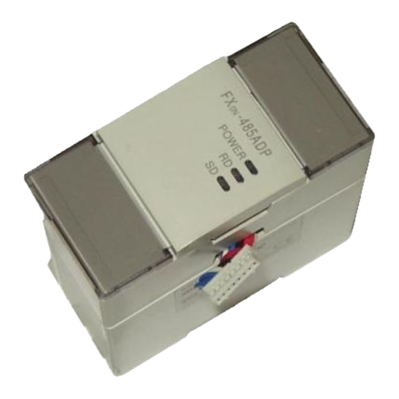
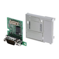
Mitsubishi Electric FX-485ADP User Manual (13 pages)
Communication Adapter
Brand:
Mitsubishi Electric
| Category:
Adapter
| Size: 0.18 MB
Table of Contents
2
External Dimensions
3
System Configuration
4
Connection with PC
7
Cautions for Wiring
8
Environmental Specifications
8
Performance Specification
9
Device Range
11
Start-Up Procedure
Share and save
Advertisement
Related Products
Mitsubishi Electric FX0N-485ADP
Mitsubishi Electric FX-485PC-IF
Mitsubishi Electric FX-4DA
Mitsubishi Electric FX-4AD
Mitsubishi Electric FX-4AD-TC
Mitsubishi Electric MELSEC FX2N-232-BD
Mitsubishi Electric MELSEC FX2NC-64MT-D/UL
Mitsubishi Electric MELSEC FX2N-232IMELSEC F
Mitsubishi Electric FX2N-E Series
Mitsubishi Electric FX3GE-24M series
Mitsubishi Electric Categories
Air Conditioner
Controller
Projector
Inverter
Monitor
More Mitsubishi Electric Manuals
Login
Sign In
OR
Sign in with Facebook
Sign in with Google
Upload manual
Upload from disk
Upload from URL