Table of Contents

Related Manuals for Kollmorgen AKD EtherCAT


Summary of Contents for Kollmorgen AKD EtherCAT
- Page 1 AKD™ EtherCAT Communication Edition December 2009 Valid for Hardware Revision A Original Documentation Keep all manuals as a product component during the life span of the product. Pass all manuals to future users / owners of the product.
- Page 2 Printed in the United States of America This document is the intellectual property of Kollmorgen™. All rights reserved. No part of this work may be reproduced in any form (by photocopying, microfilm or any other method) or stored, processed, copied or dis- tributed by electronic means without the written permission of Kollmorgen™.
-
Page 3: Table Of Contents
AKD EtherCAT | Table of Contents 1 General 1.1 About this Manual 1.2 Target Group 1.3 Warning Symbols 1.4 Abbreviations used 2 Safety 2.1 Safety Instructions 2.2 Use as directed 2.3 Prohibited use 3 Installation and Setup 3.1 Safety Instructions 3.2 EtherCAT Onboard... - Page 4 AKD EtherCAT | 4.3.1 AL Control (Address 0x0120:0x0121) 4.3.2 AL Status (Address 0x0130:0x0131) 4.3.3 AL Status Code (Address 0x0134:0x0135) 4.3.4 EtherCAT communication phases 4.4 CANopen over EtherCAT (CoE) Status Machine 4.4.1 Status Description 4.4.2 Commands in the Control Word 4.4.3 Status Machine Bits (status word) 4.5 Fixed PDO Mappings...
-
Page 5: General
AKD EtherCAT | 1 General 1 General 1.1 About this Manual 1.2 Target Group 1.3 Warning Symbols 1.4 Abbreviations used Kollmorgen | December 2009... -
Page 6: About This Manual
1.1 About this Manual This manual, AKD EtherCAT Communication, describes the installation, setup, range of functions, and soft- ware protocol for the EtherCAT AKD product series. All AKD EtherCAT drives have built-in EtherCAT func- tionality; therefore an additional option card is not required. -
Page 7: Warning Symbols
AKD EtherCAT | 1 General 1.3 Warning Symbols Symbol Indication Indicates a hazardous situation which, if not avoided, will result in death or serious injury. Indicates a hazardous situation which, if not avoided, could result in death or serious injury. -
Page 8: Abbreviations Used
AKD EtherCAT | 1 General 1.4 Abbreviations used Abbreviation Meaning Application Layer: the protocol that directly used by the process entities. Category – classification for cables that is also used in Ethernet. Distributed Clocks Mechanism to synchronize EtherCAT slaves and master Data Link(=Layer 2). -
Page 9: Safety
AKD EtherCAT | 2 Safety 2 Safety 2.1 Safety Instructions 2.2 Use as directed 2.3 Prohibited use Kollmorgen | December 2009... -
Page 10: Safety Instructions
AKD EtherCAT | 2 Safety 2.1 Safety Instructions During operation there are deadly hazards, with the possibility of death, severe injury or material damage. Do not open or touch the equipment during operation. Keep all covers and cabinet doors closed during operation. Touching the equip- ment is allowed during installation and commissioning for properly qualified per- sons only. -
Page 11: Use As Directed
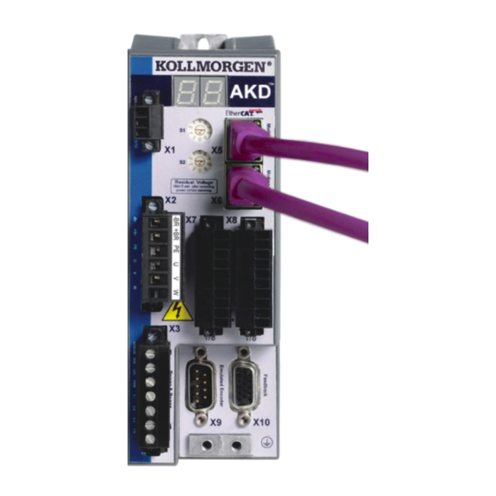
The connectors X5 and X6 of the AKD EtherCAT drive may not be used for any ethernet protocol except Ether- CAT (CoE, Can over EtherCAT). -
Page 12: Installation And Setup
AKD EtherCAT | 3 Installation and Setup 3 Installation and Setup 3.1 Safety Instructions 3.2 EtherCAT Onboard 3.3 Guide to Setup 3.4 Setup via TwinCAT NC/PTP System Manager Kollmorgen | December 2009... -
Page 13: Safety Instructions
AKD EtherCAT | 3 Installation and Setup 3.1 Safety Instructions Never undo any electrical connections to the drive while it is live. There is a danger of electrical arcing with damage to contacts and serious personal injury. Wait at least seven minutes after disconnecting the drive from the main supply power before touching potentially live sections of the equipment (e.g. -
Page 14: Ethercat Onboard
AKD EtherCAT | 3 Installation and Setup 3.2 EtherCAT Onboard Connection to the EtherCAT Network via X5 (in port) and X6 (out port). 3.2.1 LED functions The communication status is indicated by the built-in LEDs. Connector LED# Name Function LED1 IN port Link... -
Page 15: Guide To Setup
TwinCAT software from Beckhoff (NC/PTP-Mode setup) is installed. I nstall first the TwinCAT System Manager, restart your PC, then install the option package NC/PTP-Mode. The XML description of the Drive is available (the XML file on the CD-ROM or on the Kollmorgen web- site). - Page 16 AKD EtherCAT | 3 Installation and Setup A pop-up window informs you that not all devices can be detected by the TwinCAT software. Click OK to continue. Kollmorgen | December 2009...
-
Page 17: Select The Device
AKD EtherCAT | 3 Installation and Setup 3.4.2 Select the device TwinCAT must be able to find the EtherCAT network card. An EtherCAT slave must be connected to the network card; otherwise TwinCAT will find a real-time EtherNET card instead of the EtherCAT card. Press the OK button. -
Page 18: Add Slaves To Nc Tasks
AKD EtherCAT | 3 Installation and Setup 3.4.4 Add Slaves to NC tasks TwinCAT should now have identified the AKD according to the Device Description file. TwinCAT next asks if the slaves should be connected to NC tasks. Click Yes to continue. An NC task can, for example, contain a PLC program, which can be programmed by the user. -
Page 19: Enable The Network Configuration
AKD EtherCAT | 3 Installation and Setup 3.4.5 Enable the network configuration Confirm that the AKD appears in the device tree. Next, enable the network configuration Press first the button in order to generate the mappings, afterwards press the button in order to let TwinCAT check the configuration and use finally the button in order to step into run-mode. -
Page 20: Enable The Axis And Move The Axis
AKD EtherCAT | 3 Installation and Setup 3.4.6 Enable the axis and move the axis The Axis can be enabled by a mouse-click on the Set button within the Online window inside of each Axis, see also the next picture. -
Page 21: Ethercat Profile
AKD EtherCAT | 4 EtherCAT Profile 4 EtherCAT Profile 4.1 Slave Register 4.2 AL Event (Interrupt Event) and Interrupt Enable 4.3 Phase Run-Up 4.4 CANopen over EtherCAT (CoE) Status Machine 4.5 Fixed PDO Mappings 4.6 Supported Cyclical Setpoint- and Actual Values 4.7 Supported Operation Modes... -
Page 22: Slave Register
AKD EtherCAT | 4 EtherCAT Profile 4.1 Slave Register The table below gives the addresses of individual registers in the FPGA memory. The data is provided in little- endian format, with the ’least significant byte’ occupying the lowest address. A detailed description of all reg- isters and FPGA memory locations is available in the “EtherCAT Slave Controller”... -
Page 23: Al Event (Interrupt Event) And Interrupt Enable
AKD EtherCAT | 4 EtherCAT Profile 4.2 AL Event (Interrupt Event) and Interrupt Enable Communication between the drive and the EtherCAT FPGA can be interrupt-driven. The interrupt enable reg- ister and the AL event register are responsible for the EtherCAT interface interrupt functionality. -
Page 24: Al Event Request (Address 0X0220:0X0221)
AKD EtherCAT | 4 EtherCAT Profile 4.2.2 AL Event Request (Address 0x0220:0x0221) When the relevant bit of the AL event request register is set to 1, the EtherCAT interface tells the drive which event it should process by the AKD. -
Page 25: Phase Run-Up
AKD EtherCAT | 4 EtherCAT Profile 4.3 Phase Run-Up The AL control, AL status and AL status code registers are responsible for communication phase run-up (also referred to as EtherCAT status change), for current status display and for any fault messages. The drive responds to every EtherCAT interface transition request made by the AL control register via the AL Status and AL Status Code registers. -
Page 26: Al Status Code (Address 0X0134:0X0135)
AKD EtherCAT | 4 EtherCAT Profile 4.3.3 AL Status Code (Address 0x0134:0x0135) Parameter Address ZA Drive ZA ECAT Description Status 0x134 7 to 0 See table below Status 0x135 7 to 0 See table below Current Status Code Description (Status change) -
Page 27: Canopen Over Ethercat (Coe) Status Machine
AKD EtherCAT | 4 EtherCAT Profile 4.4 CANopen over EtherCAT (CoE) Status Machine The status machine for the control and status words corresponds to the CANopen status machine in accord- ance with DS402. CANopen control and status words are captured in every instance of fixed PDO mapping (see chapter entitled ‘Fixed PDO Mapping‘, page ). -
Page 28: Commands In The Control Word
AKD EtherCAT | 4 EtherCAT Profile 4.4.2 Commands in the Control Word Bit assignment in the control word Bit Name Name Switch on Pause/halt Disable Voltage reserved Quick Stop reserved Enable Operation reserved Operation mode specific reserved Operation mode specific... -
Page 29: Status Machine Bits (Status Word)
AKD EtherCAT | 4 EtherCAT Profile 4.4.3 Status Machine Bits (status word) Bit assignment in the status word Bit Name Bit Name Ready to switch on Manufacturer-specific (reserved) Switched on Remote (always 1) Operation enable 10 Target reached Fault 11 Internal limit active... -
Page 30: Fixed Pdo Mappings
AKD EtherCAT | 4 EtherCAT Profile 4.5 Fixed PDO Mappings Various ready-to-use mappings can be selected for cyclic data exchange via SDO’s of the object 0x1C12 and 0x1C13. Using object 0x1C12 subindex 1 (Sync Manager 2 assignment), a fixed mapping for the cyclic com- mand values can be set with the values 0x1701 …... -
Page 31: Adjusting Ethercat Cycle Time
AKD EtherCAT | 4 EtherCAT Profile 4.8 Adjusting EtherCAT Cycle Time The cycle time to be used in the drive for the cyclical setpoints and actual values can either be stored in the FBUS.SAMPLEPERIOD parameter in the amplifier or configured in the startup phase. -
Page 32: Latch Control Word And Latch Status Word
AKD EtherCAT | 4 EtherCAT Profile 4.11 Latch Control Word and Latch Status Word Latch Control word (2 Byte) Value (bin) Value (hex) Description 00000000 00000001 xx01 Enable extern latch 1 (positive rise) 00000000 00000010 xx02 Enable extern latch 1 (negative rise) -
Page 33: Mailbox Handling
AKD EtherCAT | 4 EtherCAT Profile 4.12 Mailbox Handling With EtherCAT, acyclical data traffic (object channel or SDO channel) is called mailbox. This system is based around the master: Mailbox Output: The master (EtherCAT controller) sends data to the slave (drive). This is essentially a (read/write) request from the master. -
Page 34: Mailbox Output
AKD EtherCAT | 4 EtherCAT Profile 4.12.1 Mailbox Output An interrupt by the EtherCAT-interface with a Sync Manager 0 - Event starts a Mailbox Output Process. A 1 in the Mail Out Event-Bit of the AL Event register signalizes the drive, that the EtherCAT-interface wants to send a Mailbox message and that it has already stored the required data in the Mail Out Buffer. -
Page 35: Mailbox Input
Byte 9 Low Byte of the CAN object number (Index) Byte 10 High Byte of the CAN object number (Index) Byte 11 Subindex according to CANopen Specification for Kollmorgen drive Byte 12 Data (Low Byte) Byte 13 Data error code Fehlercode according to CANopen Specification in case of an error ... -
Page 36: Example: Mailbox Access
AKD EtherCAT | 4 EtherCAT Profile 4.12.3 Example: Mailbox Access In the example below, PDOs 0x1704 are mapped (see Chapter # “Fixed PDO Mappings”): The master sends this mailbox output message: Byte 0 0x0A The next 10 Bytes contain data (Byte 2 to Byte 11) -
Page 37: Fieldbus Parameters
AKD EtherCAT | 4 EtherCAT Profile 4.13 Fieldbus Parameters The AKD Drive holds several fieldbus specific general purpose parameter. Some of them contain the following EtherCAT relevant data: FBUS.PARAM02: This parameter activates the synchronization feature of the AKD. The DC feature must be activated in order to allow the AKD to get synchronized with the master. - Page 38 This page intentionally left blank. Kollmorgen | December 2009...
-
Page 39: Index
AKD EtherCAT | 5 Index 5 Index Abbreviations AL Event CANopen over EtherCAT EtherCAT Proflie Interrupt Event Phase run-up Prohibited Use Safety Instructions Electrical Installation General Slave Register Symbols used Target group TwinCAT Use as directed Kollmorgen | December 2009... -
Page 40: Kollmorgen | December
This page intentionally left blank. Kollmorgen | December 2009... - Page 41 AKD EtherCAT | This page intentionally left blank Kollmorgen | December 2009...
- Page 42 E-Mail technik@kollmorgen.com Tel.: +49(0)203 - 99 79 - 0 Fax: +49(0)203 - 99 79 - 155 North America Kollmorgen Customer Support North America Internet www.kollmorgen.com E-Mail support@kollmorgen.com Tel.: +1 - 540 - 633 - 3545 Fax: +1 - 540 - 639 - 4162...
Need help?
Do you have a question about the AKD EtherCAT and is the answer not in the manual?
Questions and answers