Table of Contents
Advertisement
AKD™
AKD™ Positioner Training Manual
Rev 4.2.0
This training module is intended to provide a full understanding of AKD. This manual will help
the user to become familiar with setting up an AKD. This workbook is the prerequisite to the AKD
BASIC training manual.
Material is subject to change based on firmware and WorkBench™ design development.
Advertisement
Table of Contents

Related Manuals for Kollmorgen AKD-P01206-NBEC-0000


Summary of Contents for Kollmorgen AKD-P01206-NBEC-0000
- Page 1 AKD™ AKD™ Positioner Training Manual Rev 4.2.0 This training module is intended to provide a full understanding of AKD. This manual will help the user to become familiar with setting up an AKD. This workbook is the prerequisite to the AKD BASIC training manual.
-
Page 2: Table Of Contents
Table of Contents Introduction to AKD™ Advanced Kollmorgen Drive™ ..........4 Features of AKD ....................... 4 Benefits of AKD ......................4 Wiring the Drive for Training ..................6 Power Connections ...................... 6 Digital Inputs and Outputs .................... 7 Overview ........................8 Connect to the AKD Drive .................. - Page 3 Slider Tuner – How it Works ................... 30 Limitations of Slider Tuner ..................31 Appendix A – Under Construction ................33 Under Construction ............Error! Bookmark not defined. Appendix B – Under Construction ................35...
-
Page 4: Introduction To Akd™ Advanced Kollmorgen Drive
The WorkBench graphical user interface, or GUI, makes setup fast and intuitive. Kollmorgen servomotors with intelligent feedback devices become Plug & Play, removing the need for any motor setup. Tuning can be completed using either the Automatic mode or Manual mode. - Page 5 Part Number Break Down Support Materials Available User Guide (in WorkBench Help) • WorkBench & firmware • • Sample Motion Task & Setup...
-
Page 6: Wiring The Drive For Training
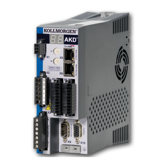
Wiring the Drive for Training The AKD Servo Drive is mounted on the base plate and wired to 115vac for training. The following schematic is provided since the base plate is prewired for simulation of an electrical cabinet. Power Connections Include on the base plate are: 115vac Circuit Breaker 24vdc Power Supply... -
Page 7: Digital Inputs And Outputs
Digital Inputs and Outputs The Digital I/O connections are made on connectors X7 & X8. Once the connections are properly made, they can be configured in WorkBench. Digital Inputs 1 & 2 both are high speed inputs with update rates of 2µs. Digital Inputs 3 to 7 are standard programmable inputs with update rates of 250 µs. -
Page 8: Overview
WorkBench - AKD™ Positioner Overview The Advanced Kollmorgen Drive is the most advanced servo drive on the market. The WorkBench software used to set-up and program the drive is an intuitive graphical user interface. The power of the AKD comes for its high level features such as: Plug-and-Play compatibility with Kollmorgen motors •... - Page 9 IP Address In order to use the AKD, you must be able to communicate with the device using WorkBench and an Ethernet connection. The AKD uses TCP/IP. Both the AKD and the PC must connect through this standard in order to communicate. Automatic (Dynamic) IP Address The IP Address for each drive can be set automatically, or dynamically.
-
Page 10: Workbench Help
WorkBench Help Within WorkBench is provided quick access to the help screens. These can be accessed using the Help tab, or the F1 key. If the Help tab is used the search screen within Help will allow you search on a specific topic. In the example a search of DRV.ACTIVE was made returning 14 results. -
Page 11: Opmode/Source/Enabled/Running
Power The Power screen allows the bus voltage to be monitored, the DC-bus Over-Voltage threshold, DC-bus Under-Voltage threshold, Under-Voltage Fault Mode, and the Operating voltage. Opmode/Source/Enabled/Running DRV.OPMODE The AKD™ servo drive has three operation modes in which it can function. operation mode, or DRV.OPMODE, of the drive is selected for the application in which the drive is being used. - Page 12 The command source can be changed from the Workbench setup screen, or from the terminal screen. If the DRV.CMDSOURCE is changed in the terminal screen while the drive is enabled the system can experience a step change in command. This can result in unexpected motion.
-
Page 13: Units
Units / Terminal / Watch window / Scope Tool Units The Units screen is used to set the three primary drive parameters of acceleration, velocity and position into user defined application specific units. This will allow the user to work in clear understandable units. Motion Task will reflect the units as they are established in this section. -
Page 14: Terminal
Terminal Terminal Screen allows parameter or command to be check and entered directly from the drive and to the drive. In most training sessions the terminal screen will be the first stop. From here the drive can be set back to factory defaults. Note: It is important to make sure you back up the parameter files before resetting the drive as all values will be overwritten. -
Page 15: Scope Tool
Scope Tool The Scope tool allows the user to collect and view six channels of data from the drive. Using the trigger mode will allow data to be collect at the same points in a move when repeated. In the Scope Tool, Channels allows the selection of parameters to be monitored, displayed, and saved for later recall. -
Page 16: Motion Task
Motion Task From the scope screen a motion task can be called. Using the motion task in the scope will allow the exact motion required for the application to be triggered and captured. A plot of the motion task can show any problems in the motion that may be occurring. -
Page 17: Cursor
Cursor To measure the values between two points the cursor can be used. The left Right Cursors can be moved to their positions and the distance between them in Time and the set units can be displayed. In the example the left cursor is set on the rising edge of the digital input 1 state. -
Page 18: Settings
Settings Settings allows for a series of Preset Scope settings to be created. These settings can be retrieved and used as needed. Clicking on the Reload Current tab will bring down the list of preset scope settings. Loading a preset will set the Channels to be recorded, the recording time, triggers etc. The preset scope settings can be exported to the computer’s memory and shared as you would any other file. -
Page 19: Akd™ Motion Task
AKD™ Motion Task Homing Before a position move can be executed, the home position must be established. Workbench provides fifteen different methods to home a system and the type selected will depend on the application and mechanics to which the motor is connected. Each home mode provides flexibility when working with the application. -
Page 20: Home Types 1, 2 & 3
Home Types 1, 2 & 3 Using Mode types 1, 2, and 3 we see that this is basically looking for the limit input, or End-Of-Travel switch (EOT). Modes 2 and 3 have the added “… then find zero angle” and “…... -
Page 21: Home Types 7 & 11
Velocity, Acceleration, and Deceleration have been set to moderate values. The Home Mode is set to type 3-Find limit input then find index (feedback incremental encoder). The direction is set to 0-Negative; this will allow the moves to be positive from home. The position is set to -1, and distance is set to 1. -
Page 22: Home Type 12
Home Type 12 Home Type 12, Find home input (account for mechanical end stops) will allow a system to travel to a hard-stop, turn around, and continue looking for the Home Reference input. This home type removes the need for adding End Of Travel limit switches to the system. It is important to be aware that this system works similar to the Home Types 8, 9 and 10, except the hard-stop is the EOT. -
Page 23: Motion Task
Relative moves are used in applications were the system can make repeated moves without coming to the end of travel such as indexing tables or conveyor systems. A clear understanding of Absolute and Relatives is required to insure that the correct move type is used in the application. - Page 24 Exercise Objective: to create a series of motion task connected together using different start conditions and blending that will be trigger from an I/O condition and captured using the Scope tool. Setup the following motion task all of which will Absolute moves, Trapezoidal Profiles, and Acceleration /Deceleration 10,000 rpm/s: Task No.
- Page 25 PLS – Programmable Limit Switches To connect the states to the OR gate, the box must be checked. The state indicator will illuminate when that point is true, and will not be illuminated when not true. PLS.EN enables the programmable limit switch. The range is 0 to 255, and is a binary representation of the 8 programmable points.
-
Page 26: Electronic Gearing
Electronic Gearing Electronic gearing allows two axis to be connected together digitally. Usually there is at least two axis involved, but it is not uncommon to have several follower axis. One axis is the Master, or Leader. The other axis, or multiple axis if more than one, is the Follower. The AKD can be setup as either the Leader or the Follower, but not both. -
Page 27: Follower
Follower The Follower has a more complex setup compared to the Leader. Because the Follower will be receiving the input, Encoder Emulation is set to 0-Input (No EEO Output). The Follower Axis will be setup for the example below. The connection will be from X9 to X9 through a 9-pin Sub-D female-to-female cable. -
Page 28: Tuning
Tuning Introduction In a perfect world tuning a system would not be required. In the “Real World” tuning a system is a necessity. A servo system is a closed loop system which will continually monitor and adjust torque, velocity, and position to achieve the desired trajectory. A servo system can operate in torque mode, or velocity mode, or position mode. -
Page 29: Slider Tuning
Slider Tuning The slider tuner is a simple easy to use tool that can get most servo systems up and running in just a few minutes. It requires two pieces of information: Load inertia Desired bandwidth Bandwidth The desired bandwidth can be entered by using the gentle/medium/stiff settings which represents 25Hz, 75Hz, or 200Hz respectively. -
Page 30: Slider Tuner - How It Works
Slider Tuner – How it Works How does the slider tuner know what the tuning gains should be just from the bandwidth and load inertia? Slider tuner will set four parameters, VL.KP (velocity proportional gain), VL.KI (velocity integral gain), PL.KP (position proportional gain), IL.KP (current proportional gain), and one biquad filter, AR1. -
Page 31: Limitations Of Slider Tuner
Next, IL BW (Current Loop Bandwidth) is clamped between 1000 Hz and 2000 Hz to maintain numerical accuracy and stability. IL BW = 1000 Hz Note: Default tuning will leave the current loop with ~1000 Hz bandwidth. If manual tuning is used to achieve more than a few hundred Hertz, IL.KP will need to be manually increased appropriately. - Page 32 Projects Project #1 Bode Tool & Tuning On your hard drive create a folder called: AKD Projects. 1. Take a Bode Plot of your system and save it to your project folder. 2. Set the tuning using the Slider Tuning.
-
Page 33: Appendix A - Under Construction
Appendix A – Always Under Construction Blending Moves When a more complex move is require, moves can be connected together using the Blend feature. The move can be connected without any blending, or blended into the acceleration or velocity of the next move. It should be noted this will only work for those motion task of the same direction. - Page 34 Motion Task 0 blended into the velocity of Motion Task 1.
-
Page 35: Under Construction
Appendix B – Under Construction Under Construction About Kollmorgen Kollmorgen is a leading provider of motion systems and components for machine builders. Through world-class knowledge in motion, industry-leading quality and deep expertise in linking and integrating standard and custom products, Kollmorgen delivers breakthrough...
Need help?
Do you have a question about the AKD-P01206-NBEC-0000 and is the answer not in the manual?
Questions and answers