Keysight Technologies N5172B EXG Manuals
Manuals and User Guides for Keysight Technologies N5172B EXG. We have 8 Keysight Technologies N5172B EXG manuals available for free PDF download: User Manual, Service Manual, Programming Manual, Getting Started Manual
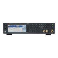
Keysight Technologies N5172B EXG User Manual (502 pages)
Signal Generators
Brand: Keysight Technologies
|
Category: Portable Generator
|
Size: 6 MB
Table of Contents
Advertisement
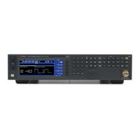
Keysight Technologies N5172B EXG User Manual (473 pages)
X-Series Signal Generators
Brand: Keysight Technologies
|
Category: Portable Generator
|
Size: 5 MB
Table of Contents

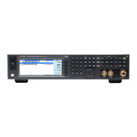
Keysight Technologies N5172B EXG Service Manual (467 pages)
Signal Generators
Brand: Keysight Technologies
|
Category: Portable Generator
|
Size: 10 MB
Table of Contents
Advertisement
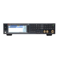
Keysight Technologies N5172B EXG User Manual (479 pages)
Signal Generators
Brand: Keysight Technologies
|
Category: Portable Generator
|
Size: 5 MB
Table of Contents

Keysight Technologies N5172B EXG Service Manual (451 pages)
Signal Generators
Brand: Keysight Technologies
|
Category: Portable Generator
|
Size: 32 MB
Table of Contents
Keysight Technologies N5172B EXG Programming Manual (398 pages)
Signal Generators
Brand: Keysight Technologies
|
Category: Portable Generator
|
Size: 3 MB
Table of Contents

Keysight Technologies N5172B EXG Getting Started Manual (61 pages)
Signal Generators
Brand: Keysight Technologies
|
Category: Portable Generator
|
Size: 0 MB
Table of Contents

Keysight Technologies N5172B EXG Getting Started Manual (61 pages)
Signal Generators
Brand: Keysight Technologies
|
Category: Test Equipment
|
Size: 0 MB
Table of Contents
Advertisement
Related Products
- Keysight Technologies N5171B EXG
- Keysight Technologies N5173B EXG
- Keysight Technologies N5171B
- Keysight Technologies N5173B
- Keysight Technologies N5171B/503
- Keysight Technologies N5183B MXG
- Keysight Technologies N5182B MXG
- Keysight Technologies N5166B CXG
- Keysight Technologies N5191-60230
- Keysight Technologies N5191-60502