Keysight Technologies X Series Getting Started Manual
Signal generators
Hide thumbs
Also See for X Series:
- Service manual (671 pages) ,
- User manual (502 pages) ,
- Measurement manual (83 pages)

Related Manuals for Keysight Technologies X Series


Summary of Contents for Keysight Technologies X Series
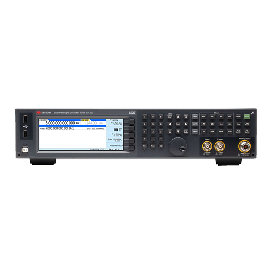
- Page 1 Keysight N5166B CXG N5171B/72B/73B EXG N5181B/82B/83B MXG X-Series Signal Generators Getting Started Guide...
- Page 2 COVERING THE MATERIAL IN THIS DOCUMENT THAT CONFLICT WITH government requirements THESE TERMS, THE WARRANTY beyond those set forth in the © Keysight Technologies, Inc. TERMS IN THE SEPARATE EULA shall apply, except to the 2012-2021 AGREEMENT WILL CONTROL. extent that those terms, rights, or...
- Page 3 Where to Find the Latest Information Documentation is updated periodically. For the latest information about these products, including instrument software upgrades, application information, and product information, browse to one of the following URLs, according to the name of your product: http://www.keysight.com/find/mxg To receive the latest updates by email, subscribe to Keysight Email Updates at the following URL: http://www.keysight.com/find/MyKeysight...
-
Page 5: Table Of Contents
Returning a Signal Generator to Keysight Technologies ........ - Page 6 Certification................. 46 Assistance .
- Page 7 Documentation Overview — Safety Information Getting Started Guide — Receiving the Instrument — Environmental & Electrical Requirements — Basic Setup — Accessories — Operation Verification — Regulatory Information — Signal Generator Overview User’s Guide — Preferences & Enabling Options — Basic Operation —...
- Page 8 — Provides a listing of SCPI commands and programming codes for Programming signal generator models that are supported by the Keysight CXG, Compatibility Guide EXG, and MXG X- Series signal generators. — Troubleshooting Service Guide — Replaceable Parts — Assembly Replacement —...
-
Page 9: Safety Information
Keysight Technologies X-Series Signal Generators Getting Started Guide Safety Information — Warnings, Cautions, and Notes on page 9 — General Safety Considerations on page 10 — Instrument Markings on page 11 Warnings, Cautions, and Notes The documentation for this product uses the following safety notations. -
Page 10: General Safety Considerations
Safety Information General Safety Considerations General Safety Considerations If the signal generator is not used as specified, the protection provided by the equipment could be impaired. The signal generator must be used in a normal condition only, in which all means for protection are intact. Personal injury may result if the signal generator covers are removed. -
Page 11: Instrument Markings
Safety Information Instrument Markings Instrument Markings The signal generator may have the following markings. Familiarize yourself with each marking and its meaning before operating the signal generator. This symbol marks the standby position of the power line switch. This symbol indicates that the input power required is AC. This symbol indicates Frame or chassis Terminal. - Page 12 Safety Information Instrument Markings China Restricted Substance Product Label. The EPUP (environmental protection use period) number in the center Indicates the time period during which no hazardous or toxic substance elements are expected to leak or deteriorate during normal use. Forty years is the expected useful life of the product.
-
Page 13: Getting Started
20 — Configuring for Remote Control on page 21 — Ordering Accessories on page 23 — Proper Use and Cleaning on page 25 — Returning a Signal Generator to Keysight Technologies on page 25 — Contacting Keysight on page 26... -
Page 14: Checking The Shipment
Getting Started Checking the Shipment Checking the Shipment 1. Inspect the shipping container for damage. Signs of damage can include a dented or torn shipping container or cushioning material that indicates signs of unusual stress or compacting. 2. Carefully remove the contents from the shipping container and verify that your order is complete. -
Page 15: Verifying Pre-Installed Software License
— TME software: www.keysight.com/find/calibrationsoftware If the software license(s) was ordered with the instrument for pre-installation and it does not show in the instrument, please contact Keysight Technologies: www.keysight.com/find/contactus Keysight CXG, EXG, and MXG X-Series Signal Generators Getting Started Guide... -
Page 16: Signal Generator Physical Characteristics
Getting Started Signal Generator Physical Characteristics Signal Generator Physical Characteristics Dimensions 88 mm H x 426 mm W x 489 mm L (length includes rear panel feet) (3.5 in H x 16.8 in W x 19.2 in L) Max length (L) including RF connector tip to end of rear panel feet is 508 mm (20 in) Weight N5171B/81B: 13.6 kg (30 lb) -
Page 17: Meeting Environmental And Electrical Requirements
Getting Started Meeting Environmental and Electrical Requirements Meeting Environmental and Electrical Requirements To avoid the loss of data, GPIB settings, or current user instrument states that have not been permanently saved to non-volatile memory, the signal generator should always be powered down either via the signal generator's front panel power button or the appropriate SCPI command. -
Page 18: Ventilation
Getting Started Meeting Environmental and Electrical Requirements The instruments can operate with mains supply voltage fluctuations up to ± 10% of the nominal voltage. Ventilation Ventilation holes are located on the rear panel and all four sides of the signal generator cover. -
Page 19: Connecting The Ac Power Cord
Getting Started Meeting Environmental and Electrical Requirements Connecting the AC Power Cord This is a Safety Class 1 Product provided with a protective earth ground incorporated into the power cord. The front panel switch is only a standby switch; it is not a line switch. The AC power cord is the disconnecting device that disconnects the signal generator mains circuits from the mains supply. -
Page 20: Configuring The Display
Getting Started Configuring the Display Configuring the Display Screen saver settings are persistent states; they are unaffected by preset or a power cycle. Use the arrow keys, numeric keypad, or front panel knob to adjust numeric values. X-Series signal generators are shipped from the factory with default display settings. -
Page 21: Configuring For Remote Control
Getting Started Configuring for Remote Control Configuring for Remote Control LAN Configuration Configuring the LAN Interface NOTES Use a 100Base-T LAN cable to connect the signal generator to the LAN. For details on using the instrument remotely, see the Programming Guide. For details on a key, press Help and then the desired key. -
Page 22: Gpib Configuration
Getting Started Configuring for Remote Control Enabling LAN Services: Browser, Sockets, and VXI-11 Use a browser to view signal generator files. Use a browser to control the signal generator GPIB Configuration For details on a key, press Help and then the desired key. Select the desired GPIB language. -
Page 23: Ordering Accessories
Getting Started Ordering Accessories Ordering Accessories Only Keysight approved accessories should be used. You can purchase accessories and find the latest documentation at: http://www.keysight.com/find/mxg If you do not have access to the Internet, please contact your Keysight field engineer. See also, “Contacting Keysight”... - Page 24 Getting Started Ordering Accessories Figure 2-2 Transit Case Lid Insert Rotomold Case - Black Base Insert Standard Plastic Handl Standard PRV Retractable Handle Casters Keysight CXG, EXG, and MXG X-Series Signal Generators Getting Started Guide...
-
Page 25: Proper Use And Cleaning
Use a dry cloth or a cloth slightly dampened with water to clean the external case parts. Returning a Signal Generator to Keysight Technologies 1. Gather as much information as possible about the signal generator’s problem. -
Page 26: Contacting Keysight
Getting Started Contacting Keysight Contacting Keysight Assistance with test and measurements needs, information on finding a local Keysight office, and information on purchasing accessories and documentation are available on the Internet at: http://www.keysight.com/find/assist If you do not have access to the Internet, please contact your Keysight field engineer. -
Page 27: Operation Verification
Keysight Technologies X-Series Signal Generators Getting Started Guide Operation Verification To avoid damaging or degrading the performance of the signal generator, do not exceed 27 dBm (0.5W) for N5173B/83B models, or 33 dBm (2W) for N5166B/71B/72B/81B/82B models, or maximum of reverse power levels at the RF input. -
Page 28: Running Self Test
Operation Verification Running Self Test Running Self Test Self Test is a series of internal tests of signal generator functions. If this test fails, refer to “Self Test Failure” on page 29 for further instructions. It takes about 5 minutes to run the self test. -
Page 29: Self Test Failure
(root failure) and any displayed error messages. Also include the model, serial number, installed options, and firmware version. “Returning a Signal Generator to Keysight Technologies” on page 25 for return instructions. Viewing Test Results If Self Test fails, the summary indicates the most significant failure (root failure). -
Page 30: Frequency Range And Accuracy Check
Operation Verification Frequency Range and Accuracy Check Frequency Range and Accuracy Check The frequency range is tested by determining the frequency accuracy relative to the timebase at the frequency limits of the signal generator. This test can be performed with a frequency counter that meets the frequency accuracy limits Table 3-1. - Page 31 Operation Verification Frequency Range and Accuracy Check Table 3-1 Frequency Accuracy Limits Frequency (MHz) Limit (Hz) 0.01 MHz ±2 0.1 MHz ±2 200 MHz ±2 300 MHz ±2 500 MHz ±2 1000 MHz ±2 2000 MHz ±2 3100 MHz ±2 6000 MHz ±2 Keysight CXG, EXG, and MXG X-Series Signal Generators Getting Started Guide...
-
Page 32: Troubleshooting Problems With The Frequency Accuracy Check
Operation Verification Checking the Output Power Troubleshooting Problems with the Frequency Accuracy Check — Verify the cables are connected correctly. — If you are using a frequency counter, verify that you are using the correct channel for the frequencies you are measuring. Checking the Output Power This test verifies that the CW output power from the signal generator is within defined limits. -
Page 33: N5171B/81B Test Procedure
Operation Verification Checking the Output Power N5171B/81B Test Procedure Test Setup 1. Connect the equipment as shown: 2. Zero and calibrate the power sensor. USB U2000A Series Power Sensors do not require the sensor to be zeroed or calibrated. 3. Connect the power sensor to the RF output of the signal generator. Once the LED on the power sensor turns off, the sensor is ready to measure. -
Page 34: N5171B/81B Alternative Test Procedure
Operation Verification Checking the Output Power N5171B/81B Alternative Test Procedure If a USB power sensor is not available, use a power meter to measure the output power of the signal generator. Test Setup 1. Zero and calibrate the power sensor to the power meter: 2. - Page 35 Operation Verification Checking the Output Power Table 3-2 Leveled Output Power Limits N5171B/81B Output Power Frequency Amplitude (dBm) Limits (dB) 125 MHz ±2 275 MHz ±2 338 MHz ±2 425 MHz ±2 538 MHz ±2 675 MHz ±2 850 MHz ±2 1075 MHz ±2...
-
Page 36: N5166B/72B/82B Test Procedure
Operation Verification Checking the Output Power N5166B/72B/82B Test Procedure Test Setup 1. Connect the equipment as shown: 2. Zero and calibrate the power sensor. USB U2000A Series Power Sensors do not require the sensor to be zeroed or calibrated. 3. Connect the power sensor to the RF output of the signal generator. Once the LED on the power sensor turns off, the sensor is ready to measure. - Page 37 Operation Verification Checking the Output Power 1. On the power meter, press the Frequency Cal Fac button. 2. If applicable, select a power meter channel. 3. Use the arrow keys to enter the frequency at which to measure the power. d.
- Page 38 Operation Verification Checking the Output Power 16.Set the frequency to the first value listed in Table 3-4: Press Frequency > 250 > MHz. 17.Set the amplitude to 7 dBm: Press Amplitude > 7 > dBm. 18.If using a power meter, configure the power meter as follows: a.
-
Page 39: N5166B/72B/82B Alternative Test Procedure
Operation Verification Checking the Output Power N5166B/72B/82B Alternative Test Procedure If a USB power sensor is not available, use a power meter to measure the output power of the signal generator. Test Setup 1. Zero and calibrate the power sensor to the power meter: 2. -
Page 40: N5173B/83B Test Procedure
Operation Verification Checking the Output Power N5173B/83B Test Procedure Test Setup 1. Connect the equipment as shown: 2. Zero and calibrate the power sensor. USB U2000A Series Power Sensors do not require the sensor to be zeroed or calibrated. 3. Connect the power sensor to the RF output of the signal generator. Once the LED on the power sensor turns off, the sensor is ready to measure. -
Page 41: N5173B/83B Alternative Test Procedure
Operation Verification Checking the Output Power N5173B/83B Alternative Test Procedure If a USB power sensor is not available, use a power meter to measure the output power of the signal generator. Test Setup 1. Zero and calibrate the power sensor to the power meter: *Refer to 2. - Page 42 Operation Verification Checking the Output Power Table 3-5 Power Sensors by Frequency and Options N5173B/83B Frequency Power Sensor Option 513/520/540 < 5GHz E9304A Option 520 > 5GHz 8485A Option 532/540 > 5GHz 8487A Table 3-6 Leveled Output Power Limits N5173B/83B Output Power Frequency Amplitude (dBm) Standard Amplitude (dBm) Option...
-
Page 43: Troubleshooting Problems With The Output Power Check
Operation Verification Checking the Output Power Troubleshooting Problems with the Output Power Check — Verify that you are using the appropriate power sensor. — Normally, power sensor calibration factors are automatically downloaded to the power meter when the power meter turns on. If this does not occur, manually enter the correct calibration factors for the power sensor you are using. - Page 44 Operation Verification Checking the Output Power Keysight CXG, EXG, and MXG X-Series Signal Generators Getting Started Guide...
-
Page 45: Regulatory Information
Keysight Technologies X-Series Signal Generators Getting Started Guide Regulatory Information — General on page 46 — Certification on page 46 — Assistance on page 46 — Statement of Compliance on page 46 — Compliance with Canadian EMC Requirements on page 46 —... -
Page 46: General
Certification Keysight Technologies certifies that this product met its published specifications at the time of shipment from the factory. Keysight Technologies further certifies that its calibration measurements are traceable to the United States National Institute of Standards and Technology, to the extent allowed by the Institute’s calibration facility, and to the calibration facilities of other... -
Page 47: South Korean Class A Emc Declaration
Regulatory Information South Korean Class A EMC Declaration South Korean Class A EMC Declaration This equipment has been conformity assessed for use in business environments. In a residential environment this equipment may cause radio interference. Compliance with European Machinery Directive Acoustic Requirement Table 4-1 Acoustic statement (European Machinery Directive 2002/42/EC, 1.7.4.2u) - Page 48 Regulatory Information Compliance with European Machinery Directive Acoustic Requirement Keysight CXG, EXG, and MXG X-Series Signal Generators Getting Started Guide...
-
Page 49: Open Source Licenses
Keysight Technologies X-Series Signal Generators Getting Started Guide Open Source Licenses This chapter contains the licenses for open source software used in the Keysight CXG, MXG and EXG X-Series signal generators. -
Page 50: Apple Mdnsresponder
Open Source Licenses Apple mDNSresponder Apple mDNSresponder Apache License Version 2.0, January 2004 http://www.apache.org/licenses/ TERMS AND CONDITIONS FOR USE, REPRODUCTION, AND DISTRIBUTION 1. Definitions. "License" shall mean the terms and conditions for use, reproduction, and distribution as defined by Sections 1 through 9 of this document. "Licensor"... - Page 51 Open Source Licenses Apple mDNSresponder copyright notice that is included in or attached to the work (an example is provided in the Appendix below). "Derivative Works" shall mean any work, whether in Source or Object form, that is based on (or derived from) the Work and for which the editorial revisions, annotations, elaborations, or other modifications represent, as a whole, an original work of authorship.
- Page 52 Open Source Licenses Apple mDNSresponder publicly display, publicly perform, sublicense, and distribute the Work and such Derivative Works in Source or Object form. 3. Grant of Patent License. Subject to the terms and conditions of this License, each Contributor hereby grants to You a perpetual, worldwide, non-exclusive, no-charge, royalty-free, irrevocable (except as stated in this section) patent license to make, have made, use, offer to sell, sell, import, and otherwise transfer the Work,...
- Page 53 Open Source Licenses Apple mDNSresponder excluding those notices that do not pertain to any part of the Derivative Works; and (d) If the Work includes a "NOTICE" text file as part of its distribution, then any Derivative Works that You distribute must include a readable copy of the attribution notices contained within such NOTICE file, excluding those notices that do not pertain to any part of the Derivative Works, in at least one...
- Page 54 Open Source Licenses Apple mDNSresponder with Licensor regarding such Contributions. 6. Trademarks. This License does not grant permission to use the trade names, trademarks, service marks, or product names of the Licensor, except as required for reasonable and customary use in describing the origin of the Work and reproducing the content of the NOTICE file.
- Page 55 Open Source Licenses Apple mDNSresponder License. However, in accepting such obligations, You may act only on Your own behalf and on Your sole responsibility, not on behalf of any other Contributor, and only if You agree to indemnify, defend, and hold each Contributor harmless for any liability incurred by, or claims asserted against, such Contributor by reason of your accepting any such warranty or additional liability.
-
Page 56: Sun Onc/Rpc
Open Source Licenses Sun ONC/RPC Sun ONC/RPC Portions of this software are copyright Sun Microsystems, Inc. and are licensed under the following terms: =*=*=*=*=*=*=*=*=*=*=*=*=*=*=*=*=*=*=*=*=*=*=*=*=*=*=*=*=*=*=*=*=*=*=*=* Sun's ONC/RPC Copyright =*=*=*=*=*=*=*=*=*=*=*=*=*=*=*=*=*=*=*=*=*=*=*=*=*=*=*=*=*=*=*=*=*=*=*=* * Sun RPC is a product of Sun Microsystems, Inc. and is provided for * unrestricted use provided that this legend is included on all tape * media and as a part of the software program in whole or part. -
Page 57: Wcelibcex - Windows Ce C Library Extensions
Open Source Licenses WCELIBCEX - Windows CE C Library Extensions WCELIBCEX - Windows CE C Library Extensions The source code of the WCELIBCEX library is licensed under MIT License: http://opensource.org/licenses/mit-license.php Permission is hereby granted, free of charge, to any person obtaining a copy of this software and associated documentation files (the "Software"), to deal in the Software without restriction, including without limitation the rights to use, copy, modify, merge, publish, distribute, sublicense, and/or sell copies of the... - Page 58 Open Source Licenses WCELIBCEX - Windows CE C Library Extensions Keysight CXG, EXG, and MXG X-Series Signal Generators Getting Started Guide...
- Page 59 Index Index ICES symbol power cord, connecting ICES-001 symbol IEC Publication 61010 accessories inspection, shipping container address, GPIB installation guide content alcohol, cleaning with instrument warm up altitude requirements interface, GPIB Australian Communications Authority (C-tick) interface, LAN mark IP address, setting auto-IP ISM1-A symbol brightness adjustment...
- Page 60 returning a signal generator safety information SCPI reference content SCPI, enabling self test server, enabling service guide content service, Keysight sales and service offices shipping container, inspection shipping requirements sockets, enabling South Korean Emc Requirements standby symbol temperature requirements troubleshooting output power user documentation content ventilation requirements...
- Page 61 This information is subject to change without notice. © Keysight Technologies 2012-2021 Edition 1, January 2021 N5180-90054 www.keysight.com...
Need help?
Do you have a question about the X Series and is the answer not in the manual?
Questions and answers