Sign In
Upload
Manuals
Brands
Keysight Manuals
Measuring Instruments
E4980AL/052
Keysight E4980AL/052 Manuals
Manuals and User Guides for Keysight E4980AL/052. We have
1
Keysight E4980AL/052 manual available for free PDF download: User Manual
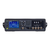
Keysight E4980AL/052 User Manual (529 pages)
Precision LCR Meter
Brand:
Keysight
| Category:
Measuring Instruments
| Size: 8.67 MB
Table of Contents
Table of Contents
3
Unpacking and Preparation
17
Contents of this Chapter
17
Checking the Shipment
18
Preparations before Use
20
Verifying the Power Supply
20
Setting up the Fuse
20
Verifying and Connecting the Power Cable
21
How to Remove the Handle
23
Caution When Using the Handle
24
Environmental Requirements
25
Operating Environments
25
Ventilation Requirements
26
Protection against Electrostatic Discharge (ESD)
27
Ensuring Adequate Free Space Around the LCR Meter for Immediate Disconnection of the Power Cable in Case of Emergency
27
Starting the E4980A/AL
28
Turning the Power on and off
28
Disconnecting from the Supply Source
29
Overview
31
Product Introduction
31
Front Panel: Names and Functions of Parts
32
Power Switch
33
Lcd
33
Softkeys
33
Menu Keys
33
Cursor Keys
33
Entry Keys
34
LED Indicator
34
Preset Key
34
Trigger Key
34
DC Bias Key
34
DC Source Key
34
UNKNOWN Terminals
35
Front USB Port
35
Ground Terminal
36
DC Source Terminal
36
Rear Panel: Names and Functions of Parts
37
GPIB Interface Connector
37
Interface Connector
37
USB (USBTMC) Interface Port
38
LAN Port
38
External Trigger Input Connector
38
Serial Number Plate
38
Power Cable Receptacle (to LINE)
39
Fan
39
Screen Area: Names and Functions of Parts
40
Display
40
Comment Line Area
40
Softkey Area
41
Measurement Data/Conditions Area
41
Input Line Area
42
System Message Area
42
Status Display Area
42
Basic Operation
43
How to Use Cursor Keys
43
How to Use Skip Keys
44
Display Format
45
MEAS DISPLAY Page
45
Measurement Function
47
Impedance Range
51
Test Frequency
58
Test Signal Level
61
DC Bias
64
Measurement Time Mode
68
Display Setting for Measurement Results
69
Displaying Errors Instead of Measurement Results
71
Monitor Information
75
BIN NO. DISPLAY Page
76
Comparator Function ON/OFF
77
BIN COUNT DISPLAY Page
79
Counter Function
81
LIST SWEEP DISPLAY Page
82
Sweep Mode
84
DISPLAY BLANK Page
86
Configuring Measurement Conditions (Display and Function Related Settings)
87
Initializing the Instrument
87
MEAS SETUP Page
88
Comment Line
90
Trigger Mode
91
Automatic Level Control
93
DC Bias Current Isolation
97
Averaging Factor
98
Trigger Delay Time
99
Step Delay Time
101
DC Bias Voltage Monitor
103
DC Bias Current Monitor
104
DCR Range
105
DCI Range
106
DC Source
107
Automatic Bias Polarity Control
108
Deviation Measurement
110
CORRECTION Page
112
To Set the Correction Function to on or off
113
The Correction Functions of the E4980A/AL Are Operated as Follows
114
Open Correction
115
Short Correction
119
Correction Based on User-Specified Frequency Points
121
Relationships between Correction Based on All Frequency Points and Correction Based on Specified Frequency Points
128
Reading/Writing Correction Data
130
Measurement Functions for the Standard
131
Selecting Single/Multiple Correction Mode
132
Selecting the Cable Length
133
LIMIT TABLE SETUP Page
134
Parameter Swap Feature
135
Comparator Limit Mode
137
Tolerance Mode Nominal Value
139
Turning On/Off the Comparator
140
Turning On/Off the Auxiliary bin
141
Beep Feature
143
Lower and Upper Limits
144
LIST SWEEP SETUP Page
147
Sweep Mode
148
List Sweep Parameters
149
Sweep Points and Limit Modes
150
Sweep Parameter Auto-Completion
153
System Configurations
155
SYSTEM INFO Page
155
Handler Interface
156
Scanner Interface
157
Monitor Information
157
SYSTEM CONFIG Page
158
Turning On/Off the Beep Feature
159
Changing the Beep Tone
160
Changing the Beep Tone
161
Configuring the System Date
161
Configuring the GPIB Address
163
Configuring the LAN IP Address
164
SELF TEST Page
166
Choosing a Test Item
167
SERVICE Page
168
Monitor Information
169
Saving the System Information into External Memory
169
Save/Recall
171
Overview of Save/Recall Functionality
171
Save Methods and Their Uses
171
Folder/File Structure on USB Memory
172
USB Memory Notes
173
Saving/Recalling Instrument Configuration States
174
Overview of Instrument Configurations
174
Medium Mode
175
Choosing a Register Number
176
Memory Status Information
176
Comment Information
177
Saving/Recalling Instrument Configuration States Into/From the Internal Memory
177
Saving/Recalling Instrument Configuration States Into/From USB Memory
179
Using the Auto Recall Feature
181
Saving Measurement Results into USB Memory
182
Measurement Result Format
182
To Save Measurement Results into USB Memory
185
How to Save the Measurement Result of List Sweep Measurement to USB Memory
186
Saving a Screenshot into USB Memory
188
To Save a Screenshot into USB Memory
188
Measurement Procedure and Examples
189
Basic Measurement Procedure
189
Impedance Parameters
191
Parallel/Series Circuit Mode
194
Selecting Circuit Mode of Capacitance
195
Selecting Circuit Mode of Inductance
196
Test Signal Level
197
Test Signal Level Across the DUT
197
Test Signal Level Setting
198
Four-Terminal Pair Configuration
199
Measurement Contacts
201
Capacitance to Ground
201
Contact Resistance
203
Extending Test Leads
204
Guarding for Measurement of Low Capacitance Values
206
Shielding
207
Correction Functions
208
Performing OPEN Correction
210
Performing SHORT Correction
210
Performing LOAD Correction
210
Parasitics Incident to DUT Connection
212
Characteristics Example
213
Capacitor Measurements
215
Inductance Measurements
218
Measurements Using DC Source
221
Overview of Remote Control
225
Types of Remote Control System
225
GPIB Remote Control System
226
What Is GPIB
226
System Configuration
226
Device Selector
227
LAN Remote Control System
228
System Configuration
228
Control over SICL-LAN Server
230
Control over Telnet Server
234
Control Via Web Server
237
USB Remote Control System
240
System Configuration
240
Sending SCPI Command Messages
246
Types and Structure of Commands
246
Grammar of Messages
247
Remote Mode
248
Trigger System
249
System-Wide States and Transitions
249
Data Buffer Memory
255
When Data Buffer Memory Is Used
256
Output Format of Data Buffer Memory
258
Starting a Measurement Cycle (Triggering the Instrument)
260
Configuring the Instrument to Automatically Perform Continuous Measurement
260
Starting Measurement on Demand
260
Waiting for the End of Measurement
262
Using the Status Register
262
Data Transfer
264
Data Format
264
Status Byte
270
Enabling the Status Byte
272
Operation Status Register Structure
273
Standard Event Status Register
276
Enabling the Event Status Register
279
Sample Program
281
Set up Measurement Conditions and LCD Display
281
Detecting End of Measurement
286
Read Measurement Results
290
Read Measurement Data in ASCII Format (Comparator)
290
Read Measurement Data in ASCII Format (Data Buffer Memory)
293
Read Measurement Data in ASCII Format (List Sweep)
296
Read Measurement Data in BINARY (Comparator)
299
Read Measurement Data in BINARY Format (Data Buffer Memory)
303
Read Measurement Data in BINARY Format (List Sweep)
306
Save/Recall
309
Read/Write Correction Data at Specified Frequency Points
312
SCPI Command Reference
319
Notational Conventions in this Command Reference
320
Syntax
320
Description
320
Parameters
320
Equivalent Key
321
E4980A/AL Commands
322
Cls
322
Ese
322
Esr
322
Idn
323
Lrn
323
Opc
323
Opt
323
Rst
323
Sre
324
Stb
324
Trg
324
Tst
324
Wai
325
Abort
325
Amplitude:alc
325
Aperture
325
Bias:current[:Level]
326
Bias:polarity:auto
327
Bias:polarity:current[:Level]
327
Bias:polarity:voltage[:Level]
327
Bias:range:auto
327
Bias:state
328
Bias:voltage[:Level]
328
Comparator:abin
329
Comparator:beeper
329
Comparator:bin:clear
330
Comparator:bin:count:clear
330
Comparator:bin:count:data
330
Comparator:bin:count[:State]
330
Comparator:mode
331
Comparator:sequence:bin
331
Comparator:slimit
332
Comparator[:State]
332
Comparator:swap
333
Comparator:tolerance:bin[1-9]
333
Comparator:tolerance:nominal
334
Control:cbias:state
334
Control:handler:state
334
Control:scanner:state
335
Correction:length
335
Correction:load:state
336
Correction:load:type
336
Correction:method
337
Correction:open[:Execute]
338
Correction:open:state
338
Correction:short[:Execute]
338
Correction:short:state
338
Correction:spot[1-201]:Frequency
339
Correction:spot[1-201]:Load[:Execute]
339
Correction:spot[1-201]:Load:standard
339
Correction:spot[1-201]:Open[:Execute]
340
Correction:spot[1-201]:Short[:Execute]
340
Correction:spot[1-201]:State
340
Correction:use[:Channel]
341
Correction:use:data[:Multi]
341
Correction:use:data:single
342
Current[:Level]
343
Display:cclear
343
Display:enable
343
Display:line
344
Display:page
344
Display[:Window]:Text[1-2][:DATA]:FMSD:DATA
345
Display[:Window]:Text[1-2][:Data]:Fmsd[:State]
346
Fetch[:Impedance]:Corrected
346
Fetch[:Impedance][:Formatted]
346
Fetch:smonitor:iac
347
Fetch:smonitor:IDC
347
Fetch:smonitor:vac
347
Fetch:smonitor:VDC
347
Format:ascii:long
347
Format:border
348
Format[:Data]
348
Format:exponent:digit
349
Frequency[:Cw]
349
Function:dcresistance:range:auto
350
Function:dcresistance:range[:Value]
350
Function:dev[1-2]:MODE
350
Function:dev[1-2]:Reference:fill
351
Function:dev[1-2]:Reference[:Value]
351
Function:impedance:range:auto
352
Function:impedance:range[:Value]
352
Function:impedance[:Type]
353
Function:smonitor:iac[:State]
354
Function:smonitor:IDC[:State]
354
Function:smonitor:vac[:State]
355
Function:smonitor:VDC[:State]
355
Hcopy:sdump:data
356
Initiate:continuous
356
Initiate[:Immediate]
357
List:band[1-201]
357
List:bias:current
358
List:bias:voltage
358
List:clear:all
358
List:current
359
List:dcsource:voltage
359
List:frequency
360
List:mode
360
List:sequence:tstamp:clear
360
List:sequence:tstamp:data
361
List:stimulus:data
361
List:stimulus:mdata
362
List:stimulus:type
362
List:voltage
363
Memory:clear
363
Memory:DIM
364
Memory:fill
364
Memory:read
364
Mmemory:delete[:Register]
365
Mmemory:load:state[:Register]
365
Mmemory:store:state[:Register]
365
Output:DC:isolation:level:auto
366
Output:DC:isolation:level:value
366
Output:DC:isolation[:State]
367
Output:hpower
367
Source:dcsource:state
367
Source:dcsource:voltage[:Level]
368
Status:operation:condition
368
Status:operation:enable
369
Status:operation[:Event]
369
System:beeper[:Immediate]
369
System:beeper:state
369
System:beeper:tone
370
System:communicate:gpib[:Self]:Address
370
System:communicate:lan[:Self]:Address
371
System:communicate:lan[:Self]:Aip[:State]
371
System:communicate:lan[:Self]:Configure
372
System:communicate:lan[:Self]:Control
372
System:communicate:lan[:Self]:Current:address
372
System:communicate:lan[:Self]:Current:dgateway
372
System:communicate:lan[:Self]:Current:smask
373
System:communicate:lan[:Self]:Dgateway
373
System:communicate:lan[:Self]:Dhcp[:State]
373
System:communicate:lan[:Self]:Mac
374
System:communicate:lan[:Self]:Preset
374
System:communicate:lan[:Self]:Restart
374
System:communicate:lan[:Self]:Smask
374
System:date
375
System:error[:Next]
376
System:klock
376
System:persona:manufacturer[:Name]
376
System:persona:manufacturer:default
376
System:preset
377
System:restart
377
System:time
377
Trigger:delay
378
Trigger[:Immediate]
378
Trigger:source
378
Trigger:tdel
379
Voltage[:Level]
379
Command List
381
List by Function
381
Command Tree
388
Softkey Functions
397
Data Processing
415
Specifications and Supplemental Information
417
Precautions for Use and Daily Checks
419
Precautions for Use
419
Avoiding Improper Input from the Front Panel (Key Lock Function)
419
Daily Checks (Executing the Self-Test)
421
Self-Test at Power on
421
Executing the Self-Test from the Front Panel
421
Cleaning this Instrument
423
Unknown Terminals/DC Source Ports
423
Cleaning Parts Other than Unknown Terminals and DC Source Ports
423
Cautions Applicable to Requesting Repair, Replacement, Regular Calibration, Etc
424
Caution When Sending the Unit
424
Recommended Calibration Period
424
Troubleshooting
425
Primary Trouble Isolation
425
Check Items When Trouble Occurs
427
The System Does Not Start up (Nothing Is Displayed)
427
The System Starts Up, but the Normal Measurement Screen Does Not Appear (Service Mode)
427
An Overload Message Is Displayed
427
Beeping Persists When Turning on the Comparator Function
428
The Front Panel Keys Are Unavailable
428
Clearly Abnormal Measured Value
428
Saving to USB Memory Fails
429
An Error Message or Warning Message Is Displayed
429
Check Items When Trouble Occurs During Remote Control
430
The Instrument Does Not Respond to the External Controller or Malfunctions
430
You Cannot Read out the Measured Value
430
An Error Message Is Displayed
430
A.manual Changes
431
Manual Changes
431
Change 5
432
Change 4
432
Change 3
432
Change 2
432
Change 1
432
B.error Messages
435
Error Messages
435
Error Messages Category
435
GPIB Devices in IEEE488.2
436
Setup
440
Hardware
444
Warning Messages
446
Numeric
446
C.list of Default Values
449
List of Default Values, Save/Recall Settings, and Backup Settings
450
List of Default Values
451
List of LAN Factory Default Settings
455
D.bias Current Interface
457
Product Overview
458
42841A Bias Current Source
458
Operation Limitations
458
Specifications When Measuring with the 42841A
459
Preparation
460
Equipment Requirements
460
Cable Connection
460
Measurement Procedures
464
E.handler Interface
465
Overview
465
Specifications
466
Output Signals
466
Input Signals
466
Signal Line Definitions
467
Signal Line Definitions for the Comparator
467
Signal Line Definitions for the List Sweep Comparator
473
Electrical Characteristics
478
DC Isolation Output Signals
478
DC Isolation Input Signals (Photo-Coupled)
480
Setting up the Handler Interface Board
483
Using the Handler Interface
490
Setting up the Handler Interface for Use with the Comparator
490
Setting up the Handler Interface Board for Use with the List Sweep Comparator
491
Signals Activated When Overload Occurs
492
F.scanner Interface
493
Overview
494
Specifications
495
Supplemental Performance Characteristics
495
Signal Input/Output Connector
496
Scanner Interface Input/Output Signals
496
Scanner Interface I/O Connector Pin Assignments
498
Timing Chart
500
Electrical Characteristics of the Input/Output Signals
504
Channel Selection Input Signals
504
External Trigger Input Signals
504
Control Output Signals
507
Setting up the Scanner Interface Board
508
How to Use the Scanner Interface Board
510
Basic Procedure
510
Activating Scanner Interface
512
Correction Mode
512
Test Frequency and Reference Value Entry
512
Correction Data Selection
514
Correction Data Measurements
516
Activating the Correction Function
517
Correction Data Confirmation
517
G.functional Comparison between 4284A, 4279A and E4980A/AL
521
Functional Comparison between 4284A, 4279A, and E4980A/AL
521
Advertisement
Advertisement
Related Products
Keysight E4980A
Keysight E4980AAL
Keysight E4980AL
Keysight E4980AL/032
Keysight E4980AL/102
Keysight E4981A
Keysight E4982A
Keysight E4981A/001
Keysight E4981A/002
Keysight E4990A
Keysight Categories
Measuring Instruments
Test Equipment
Multimeter
Control Unit
Portable Generator
More Keysight Manuals
Login
Sign In
OR
Sign in with Facebook
Sign in with Google
Upload manual
Upload from disk
Upload from URL