Sign In
Upload
Manuals
Brands
IEI Technology Manuals
Single board computers
WSB-PV-D4251
IEI Technology WSB-PV-D4251 Manuals
Manuals and User Guides for IEI Technology WSB-PV-D4251. We have
1
IEI Technology WSB-PV-D4251 manual available for free PDF download: User Manual
IEI Technology WSB-PV-D4251 User Manual (137 pages)
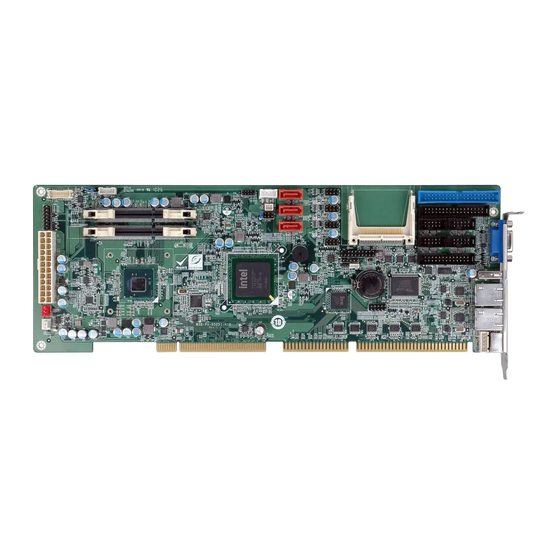
Full-size PICMG 1.0 Intel Atom Processor D525/D425 DDR3 up to 4GB, VGA/LDVS, Dual PCIe GbE Four RS-232 Ports, Three SATA 3Gb/s Ports Seven USB 2.0, RoHS, Audio
Brand:
IEI Technology
| Category:
Single board computers
| Size: 7.56 MB
Table of Contents
Table of Contents
4
1 Introduction
14
Introduction
15
Benefits
15
Features
15
Figure 1-1: WSB-PV-D4251/D5251
15
Connectors
16
Figure 1-2: Connectors
16
Dimensions
17
Figure 1-3: Dimensions (MM)
17
Data Flow
18
Figure 1-4: Data Flow Diagram
18
Technical Specifications
19
Table 1-1: Technical Specifications
20
2 Packing List
21
Anti-Static Precautions
22
Unpacking Precautions
22
Packing List
23
Optional Items
24
Table 2-1: Packing List
24
Table 2-2: Optional Items
25
3 Connector Pinouts
26
Peripheral Interface Connectors
27
Figure 3-1: Connector and Jumper Locations
27
Layout
27
External Interface Panel Connectors
28
Table 3-1: Peripheral Interface Connectors
28
Table 3-2: Rear Panel Connectors
28
Internal Peripheral Connectors
29
ATX Power Control Connector
29
ATX Power Source Connector
29
Figure 3-2: ATX Power Control Connector Location
29
Table 3-3: ATX Power Control Pinouts
29
Audio Connector
30
Figure 3-3: ATX Power Source Connector Location
30
Table 3-4: ATX Power Source Pinouts
30
Compactflash® Slot
31
Figure 3-4: Audio Connector Location
31
Table 3-5: Audio Connector Pinouts
31
Figure 3-5: Compactflash® Slot Location
32
Digital I/O Connector
33
Fan Connector
33
Figure 3-6: Digital I/O Connector Location
33
Table 3-6: Compactflash® Slot Pinouts
33
Table 3-7: Digital I/O Connector Pinouts
33
Figure 3-7: Fan Connector Locations
34
Figure 3-8: Front Panel Connector Location
34
Front Panel Connector
34
Table 3-8: Fan Connector Pinouts
34
Figure 3-9: IDE Connector Location
35
IDE Connector
35
Table 3-9: Front Panel Connector Pinouts
35
Figure 3-10: Keyboard Connector Location
36
Keyboard Connector
36
Table 3-10: IDE Connector Pinouts
36
Figure 3-11: Inverter Connector Location
37
Inverter Connector
37
Irda Infared Interface Connector
37
Table 3-11: Keyboard Connector Pinouts
37
Table 3-12: Inverter Connector Pinouts
37
Figure 3-12: Irda Infrared Interface Connector Location
38
Figure 3-13: LVDS Connector Location
38
LVDS Connector
38
Table 3-13: Irda Infrared Interface Connector Pinouts
38
Figure 3-14: Parallel Port Connector
39
Parallel Port Connector
39
Table 3-14: LVDS Connector Pinouts
39
Figure 3-15: RS-232 Serial Port Connector Location
40
Serial Port Connector
40
Table 3-15: Parallel Port Connector Pinouts
40
Table 3-16: RS-232 Serial Port Connector Pinouts
40
Figure 3-16: SATA Drive Connector Location
41
SATA Drive Connectors
41
Smbus
41
Table 3-17: SATA Drive Connector Pinouts
41
Figure 3-17: Smbus Connector Locations
42
Figure 3-18: TPM Module Connector Locations
42
Table 3-18: Smbus Connector Pinouts
42
TPM Module Connector
42
Figure 3-19: USB Connector Location
43
Table 3-19: TPM Module Connector Pinouts
43
Table 3-20: USB Port Connector Pinouts
43
USB Connectors
43
External Interface Connectors
44
Figure 3-20: External Interface Connectors
44
Figure 3-21: Keyboard Pinout and Configuration
44
Keyboard/Mouse Connector
44
Table 3-21: Keyboard Connector Pinouts
44
Ethernet Connectors
45
Figure 3-22: Ethernet Connector
45
Table 3-22: LAN Connector Pinouts
45
Table 3-23: RJ-45 Ethernet Connector Leds
45
Figure 3-23: VGA Connector
46
Table 3-24: USB Connector Pinouts
46
USB Port
46
VGA Connector
46
Table 3-25: VGA Connector Pinouts
47
4 Installation
48
Anti-Static Precautions
49
Installation Considerations
50
So-DIMM Installation
51
Figure 4-1: SO-DIMM Installation
51
Compactflash® Installation
52
Figure 4-2: Compactflash® Card Installation
52
Jumper Settings
53
Clear CMOS Jumper
53
Table 4-1: Jumpers
53
CF Card Jumper
54
Figure 4-3: Clear CMOS Jumper Location
54
Table 4-2: Clear CMOS Jumper Settings
54
Figure 4-4: CF Card Jumper Location
55
LCD Panel Resolution Jumper
55
Table 4-3: CF Card Jumper Settings
55
Figure 4-5: LCD Panel Resolution Jumper Location
56
LCD Voltage Select Jumper
56
Table 4-4: LCD Panel Resolution Jumper Settings
56
Table 4-5: LCD Voltage Selection
56
Chassis Installation
57
Airflow
57
Motherboard Installation
57
Internal Peripheral Device Connections
57
Dual RS-232 Cable with Slot Bracket
57
Figure 4-6: LCD Voltage Select Jumper Location
57
Figure 4-7: Dual RS-232 Cable Installation
58
SATA Drive Connection
58
Figure 4-8: SATA Drive Cable Connection
59
Figure 4-9: SATA Power Drive Connection
60
USB Cable (Dual Port) with Slot Bracket
60
External Peripheral Interface Connection
61
Figure 4-10: Dual USB Cable Connection
61
Figure 4-11: PS/2 Connector
62
LAN Connection (Single Connector)
62
PS/2 Keyboard/Mouse Connection
62
Figure 4-12: LAN Connection
63
USB Device Connection (Single Connector)
63
Figure 4-13: USB Device Connection
64
VGA Monitor Connection
64
Software Installation
65
Figure 4-14: VGA Connector
65
Figure 4-15: Introduction Screen
66
Figure 4-16: Available Drivers
66
5 Bios
67
Introduction
68
Starting Setup
68
Using Setup
68
BIOS Menu Bar
69
Getting Help
69
Table 5-1: BIOS Navigation Keys
69
Unable to Reboot after Configuration Changes
69
Main
70
BIOS Menu 1: Main
70
BIOS Information
70
System Date [XX/XX/XX]
70
ACPI Configuration
71
Advanced
71
BIOS Menu 2: Advanced
71
System Time [XX:XX:XX]
71
Trusted Computing
72
BIOS Menu 3: ACPI Configuration
72
ACPI Sleep State [S1 (CPU Stop Clock)]
72
BIOS Menu 4: TPM Configuration
73
TPM Support [Disable]
73
CPU Configuration
74
BIOS Menu 5: CPU Configuration
74
IDE Configuration
75
BIOS Menu 6: IDE Configuration
75
ATA or IDE Configurations [Enhanced]
75
USB Configuration
76
BIOS Menu 7: USB Configuration
76
Configure SATA as [IDE]
76
USB 2.0(EHCI) Support
76
USB Devices
76
USB Function
76
Legacy USB Support [Enabled]
77
Super IO Configuration
78
BIOS Menu 8: Super IO Configuration
78
Floppy Disk Controller Configuration
79
BIOS Menu 9: Floppy Disk Controller Configuration Menu
79
Floppy Disk Controller [Enabled]
79
Serial Port N Configuration
80
BIOS Menu 10: Serial Port N Configuration Menu
80
Change Settings [Auto]
80
Serial Port [Enabled]
80
Change Settings [Auto]
81
Serial Port [Enabled]
81
Change Settings [Auto]
82
Serial Port [Enabled]
82
Change Settings [Auto]
83
Irda Configuration
84
BIOS Menu 11: Irda Configuration Menu
84
Irda [Enabled]
84
Parallel Port Configuration
85
BIOS Menu 12: Parallel Port Configuration Menu
85
Change Settings [Auto]
85
Parallel Port [Enabled]
85
Device Mode [Printer Mode]
86
H/W Monitor
87
BIOS Menu 13: Hardware Health Configuration
87
PC Health Status
87
CPU Smart Fan Control [Auto Mode]
88
Serial Port Console Redirection
88
Chipset
89
BIOS Menu 14: Serial Port Console Redirection
89
Console Redirection [Disabled]
89
Host Bridge
90
BIOS Menu 15: Chipset
90
BIOS Menu 16:Host Bridge Configuration
90
Share Memory Size [8MB]
90
South Bridge
91
BIOS Menu 17:Southbridge Chipset Configuration
91
Initiate Graphics Adapter [PEG/IGD]
91
HD Audio Controller [Enabled]
92
Intel IGD SWSCI Opregion
92
Restore on AC Power Loss [Last State]
92
Set Spread Spectrum Function [Disabled]
92
BIOS Menu 18: Intel IGD SWSCI Opregion
93
DVMT Mode Select [DVMT Mode]
93
DVMT/FIXED Memory [Maximum]
93
IGD - Boot Type [VBIOS Default]
93
LCD Panel Type [VBIOS Default]
93
Boot
95
BIOS Menu 19: Boot
95
Bootup Numlock State [On]
95
Security
96
BIOS Menu 20: Security
96
Administrator Password
96
Launch PXE Oprom [Disabled]
96
Quiet Boot [Enabled]
96
Set User Password
96
User Password
96
Exit
97
BIOS Menu 21:Exit
97
Discard Changes and Reset
97
Restore Defaults
97
Save Changes and Reset
97
Restore User Defaults
98
Save as User Defaults
98
ABIOS Options
99
Appendix A
100
B One Key Recovery
102
One Key Recovery Introduction
103
Figure B-1: IEI One Key Recovery Tool Menu
103
B.1 O Ne K Ey R Ecovery I Ntroduction
103
System Requirement
104
Supported Operating System
105
Setup Procedure for Windows
106
Hardware and BIOS Setup
106
Create Partitions
107
Figure B-2: Launching the Recovery Tool
107
Figure B-3: Recovery Tool Setup Menu
108
Figure B-4: Command Mode
108
Figure B-5: Partition Creation Commands
109
Install Operating System, Drivers and Applications
110
Build-Up Recovery Partition
111
Figure B-6: Launching the Recovery Tool
111
Figure B-7: System Configuration for Windows
111
Figure B-8: Build-Up Recovery Partition
112
Figure B-9: Press any Key to Continue
112
Create Factory Default Image
113
Figure B-10: Press F3 to Boot into Recovery Mode
113
Figure B-11: Recovery Tool Menu
113
Figure B-12: about Symantec Ghost Window
114
Figure B-13: Symantec Ghost Path
114
Figure B-14: Select a Local Source Drive
115
Figure B-15: Select a Source Partition from Basic Drive
115
Figure B-16: File Name to Copy Image to
116
Figure B-17: Compress Image
116
Figure B-18: Image Creation Confirmation
117
Figure B-19: Image Creation Process
117
Figure B-20: Image Creation Complete
117
Setup Procedure for Linux
118
Figure B-21: Press any Key to Continue
118
Figure B-22: Partitions for Linux
119
Figure B-23: System Configuration for Linux
120
Figure B-24: Access Menu.lst in Linux (Text Mode)
120
Recovery Tool Functions
121
Figure B-25: Recovery Tool Menu
121
Figure B-26: Recovery Tool Main Menu
122
Factory Restore
123
Figure B-27: Restore Factory Default
123
Figure B-28: Recovery Complete Window
123
Backup System
124
Figure B-29: Backup System
124
Figure B-30: System Backup Complete Window
124
Figure B-31: Restore Backup
125
Figure B-32: Restore System Backup Complete Window
125
Restore Your Last Backup
125
Figure B-33: Symantec Ghost Window
126
Manual
126
Other Information
127
B.5 O THER I NFORMATION B.5.1 Using AHCI Mode or Ali M5283 / VIA VT6421A Controller
127
Using AHCI Mode or Ali M5283 / VIA VT6421A Controller
127
System Memory Requirement
129
C Terminology
130
D Hazardous Materials Disclosure
134
Hazardous Materials Disclosure Table for IPB Products Certified as Rohs Compliant under 2002/95/EC Without Mercury
135
Advertisement
Advertisement
Related Products
IEI Technology WSB-PV-D5251
IEI Technology WAFER-ULT-i1
IEI Technology WAFER-ULT2-i1
IEI Technology WAFER-945GSE3
IEI Technology WAFER-ULT5
IEI Technology WAFER-PV-D4252-R11
IEI Technology WAFER-CV-N25501 Series
IEI Technology WAFER-CV-D26001-R10
IEI Technology WAFER-JL-N5105
IEI Technology WAFER-JL-N5105-R10
IEI Technology Categories
Motherboard
Touch Panel
Computer Hardware
Single board computers
Desktop
More IEI Technology Manuals
Login
Sign In
OR
Sign in with Facebook
Sign in with Google
Upload manual
Upload from disk
Upload from URL