Sign In
Upload
Manuals
Brands
IEI Technology Manuals
Single board computers
WAFER-CV-D26001-R10
IEI Technology WAFER-CV-D26001-R10 Manuals
Manuals and User Guides for IEI Technology WAFER-CV-D26001-R10. We have
1
IEI Technology WAFER-CV-D26001-R10 manual available for free PDF download: User Manual
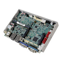
IEI Technology WAFER-CV-D26001-R10 User Manual (135 pages)
Intel Atom D2550 1.86GHz, DDR3, VGA/LVDS, Dual PCIe GbE, USB 2.0
Brand:
IEI Technology
| Category:
Single board computers
| Size: 7.37 MB
Table of Contents
Table of Contents
5
Introduction
15
Introduction
16
Model Variations
16
Figure 1-1: WAFER-CV-D25501/N26001
16
Table 1-1: WAFER-CV-D25501/N26001 Model Variations
16
Connectors
17
Figure 1-2: Connectors
17
Dimensions
18
Figure 1-3: WAFER-CV-D25501/N26001 Dimensions (MM)
19
Data Flow
20
Figure 1-4: Data Flow Diagram
20
Technical Specifications
21
Table 1-2: WAFER-CV-D25501/N26001 Specifications
22
Packing List
23
Anti-Static Precautions
24
Unpacking Precautions
24
Packing List
25
Optional Items
26
Table 2-1: Packing List
26
Table 2-2: Optional Items
26
Connectors
27
Peripheral Interface Connectors
28
WAFER-CV-D25501/N26001 Layout
28
Figure 3-1: Connectors and Jumpers
28
Peripheral Interface Connectors
29
Table 3-1: Peripheral Interface Connectors
29
External Interface Panel Connectors
30
Internal Peripheral Connectors
30
SATA Power Connectors
30
Figure 3-2: 5 V SATA Power Connector Locations
30
Table 3-2: Rear Panel Connectors
30
Power Connector
31
Audio Connector
31
Figure 3-3: 12 V Power Connector Location
31
Table 3-3: 5 V SATA Power Connector Pinouts
31
Table 3-4: 12 V Power Connector Pinouts
31
Backlight Inverter Connectors
32
Figure 3-4: Audio Connector Location
32
Table 3-5: Audio Connector Pinouts
32
Battery Connector
33
Figure 3-5: Backlight Inverter Connector Locations
33
Table 3-6: Backlight Inverter Connector Pinouts
33
Digital Input/Output (DIO) Connector
34
Figure 3-6: Battery Connector Location
34
Table 3-7: Battery Connector Pinouts
34
Fan Connectors
35
Figure 3-7: Digital I/O Connector Location
35
Table 3-8: Digital I/O Connector Pinouts
35
Keyboard/Mouse Connector
36
Figure 3-8: Fan Connector Locations
36
Table 3-9: Fan Connector Pinouts
36
LVDS1 Connector
37
Figure 3-9: Keyboard/Mouse Connector Location
37
Table 3-10: Keyboard/Mouse Connector Pinouts
37
LVDS2 Connector
38
Figure 3-10: LVDS1 Connector Location
38
Table 3-11: LVDS1 Connector Pinouts
38
Figure 3-11: LVDS2 Connector Location
39
Table 3-12: LVDS2 Connector Pinouts
39
LVDS2 Backlight Control Connector
40
Pcie Mini Card Slots
40
Figure 3-12: LVDS2 Backlight Control Connector Location
40
Table 3-13: LVDS2 Backlight Control Connector Pinouts
40
Figure 3-13: Pcie Mini Card Slot Locations
41
Power & HDD LED Connector
42
Figure 3-14: Power & HDD LED Connector Location
42
Table 3-14: Pcie Mini Card Slot Pinouts
42
Power Button Connector
43
Figure 3-15: Power Button Connector Location
43
Table 3-15: Power & HDD LED Connector Pinouts
43
Table 3-16: Power Button Connector Pinouts
43
Reset Button Connector
44
Serial Port Connectors
44
Figure 3-16: Reset Button Connector Location
44
Table 3-17: Reset Button Connector Pinouts
44
RS-422/485 Serial Port Connector
45
Figure 3-17: RS-232 Serial Port Connector Locations
45
Table 3-18: RS-232 Serial Port Connector Pinouts
45
SATA Drive Connectors
46
Figure 3-18: RS-422/485 Connector Location
46
Figure 3-19: SATA Drive Connector Locations
46
Table 3-19: RS-422/485Connector Pinouts
46
USB Connectors
47
Figure 3-20: USB Connector Locations
47
Table 3-20: SATA Drive Connector Pinouts
47
External Peripheral Interface Connector Panel
48
Ethernet Connectors
48
Figure 3-21: External Peripheral Interface Connector
48
Table 3-21: USB Connector Pinouts
48
Table 3-22: LAN Pinouts
48
Serial Port Connector (COM1)
49
Figure 3-22: RJ-45 Ethernet Connector
49
Figure 3-23: COM1 Pinout Locations
49
Table 3-23: RJ-45 Ethernet Connector Leds
49
Table 3-24: RS-232 Serial Port (COM 1) Pinouts
49
USB Connectors
50
VGA Connector
50
Table 3-25: USB Port Pinouts
50
Table 3-26: VGA Connector Pinouts
50
Figure 3-24: VGA Connector
51
Installation
52
Anti-Static Precautions
53
Installation Considerations
53
So-DIMM Installation
55
Figure 4-1: SO-DIMM Installation
55
Jumper Settings
56
AT/ATX Power Selection Jumper
56
Table 4-1: Jumpers
56
Clear CMOS Jumper
57
Figure 4-2: AT/ATX Power Selection Jumper Location
57
Table 4-2: AT/ATX Power Selection Jumper Settings
57
Table 4-3: Clear CMOS Jumper Settings
57
LVDS1 Voltage Selection
58
Figure 4-3: Clear CMOS Jumper Location
58
Table 4-4: LVDS1 Voltage Selection Jumper Settings
58
LVDS2 Voltage Selection
59
Figure 4-4: LVDS1 Voltage Selection Jumper Location
59
Table 4-5: LVDS2 Voltage Selection Jumper Settings
59
LVDS2 Panel Type Selection Jumper
60
Figure 4-5: LVDS2 Voltage Selection Jumper Location
60
Chassis Installation
61
Heat Sink Enclosure
61
Figure 4-6: LVDS2 Panel Type Selection Switch Location
61
Table 4-6: LVDS2 Panel Resolution
61
Figure 4-7: Heat Sink Retention Screws
62
Motherboard Installation
63
Figure 4-8: Motherboard Installation Example
63
Internal Peripheral Device Connections
64
Audio Kit Installation
64
Figure 4-9: Audio Kit Cable Connection
64
LVDS LCD Installation
65
Figure 4-10: LVDS Connector
66
Full-Size Pcie Mini Card Installation
67
Figure 4-11: Backlight Inverter Connection
67
Figure 4-12: Remove the Retention Screw for the Full-Size Pcie Mini Card
68
Figure 4-13: Insert the Full-Size Pcie Mini Card into the Socket at an Angle
68
Half-Size Pcie Mini Card Installation
69
Figure 4-14: Secure the Full-Size Pcie Mini Card
69
Figure 4-15: Remove the Retention Screws for the Half-Size Pcie Mini Card
69
SATA Drive Connection
70
Figure 4-16: Insert the Half-Size Pcie Mini Card into the Socket at an Angle
70
Figure 4-17: Secure the Half-Size Pcie Mini Card
70
Single RS-232 Cable
71
Figure 4-18: SATA Drive Cable Connection
71
Keyboard/Mouse Y-Cable Connector
72
Figure 4-19: Single RS-232 Cable Installation
72
Figure 4-20: Keyboard/Mouse Y-Cable Connection
73
Bios
75
Introduction
76
Starting Setup
76
Using Setup
76
Getting Help
77
Unable to Reboot after Configuration Changes
77
BIOS Menu Bar
77
Table 5-1: BIOS Navigation Keys
77
Main
78
BIOS Menu 1: Main
78
Advanced
79
ACPI Settings
79
BIOS Menu 2: Advanced
79
RTC Wake Settings
80
BIOS Menu 3: ACPI Settings
80
BIOS Menu 4: RTC Wake Settings
81
CPU Configuration
82
BIOS Menu 5: CPU Configuration
82
IDE Configuration
83
BIOS Menu 6: IDE Configuration
83
USB Configuration
84
BIOS Menu 7: USB Configuration
84
F81866 Super IO Configuration
85
Serial Port N Configuration
85
BIOS Menu 8: Super IO Configuration
85
BIOS Menu 9: Serial Port N Configuration Menu
85
F81866 H/W Monitor
89
BIOS Menu 10: F81866 H/W Monitor
89
Smart Fan Mode Configuration
90
Serial Port Console Redirection
91
BIOS Menu 11: Smart Fan Mode Configuration
91
BIOS Menu 12: Serial Port Console Redirection
92
Iei Feature
94
BIOS Menu 13: IEI Feature
94
Chipset
95
Host Bridge Configuration
95
BIOS Menu 14: Chipset
95
Intel IGD Configuration
96
BIOS Menu 15: Host Bridge Configuration
96
BIOS Menu 16: Intel IGD Configuration
96
South Bridge Configuration
98
BIOS Menu 17: Southbridge Chipset Configuration
98
Boot
99
BIOS Menu 18: Boot
99
Security
101
Exit
101
BIOS Menu 19: Security
101
BIOS Menu 20:Exit
102
Software Drivers
103
Available Software Drivers
104
Starting the Driver Program
104
Chipset Driver Installation
105
Figure 6-1: Chipset Driver Screen
105
Figure 6-2: Chipset Driver Welcome Screen
106
Figure 6-3: Chipset Driver License Agreement
107
Figure 6-4: Chipset Driver Read Me File
107
Figure 6-5: Chipset Driver Setup Operations
108
Graphics Driver Installation
109
Figure 6-6: Chipset Driver Installation Finish Screen
109
Figure 6-7: Graphics Driver Welcome Screen
110
Figure 6-8: Graphics Driver License Agreement
111
Figure 6-9: Graphics Driver Read Me File
111
Figure 6-10: Graphics Driver Setup Operations
112
Figure 6-11: Graphics Driver Installation Finish Screen
112
Lan Driver Installation
113
Figure 6-12: LAN Driver Welcome Screen
113
Figure 6-13: LAN Driver Installation
114
Figure 6-14: LAN Driver Installation Complete
114
Audio Driver Installation
115
Figure 6-15: Audio Driver Installation File Extraction
115
Figure 6-16: Audio Driver Welcome Screen
116
Figure 6-17: Audio Driver Installation
116
A Regulatory Compliance
118
BBIOS Options
120
C Terminology
123
D Digital I/O Interface
127
Introduction
128
Assembly Language Sample 1
129
Assembly Language Sample 2
129
E Watchdog Timer
130
F Hazardous Materials Disclosure
133
Advertisement
Advertisement
Related Products
IEI Technology WAFER-CV-N25501 Series
IEI Technology WAFER-ULT-i1
IEI Technology WAFER-ULT2-i1
IEI Technology WAFER-945GSE3
IEI Technology WAFER-ULT5
IEI Technology WAFER-PV-D4252-R11
IEI Technology WAFER-JL-N5105
IEI Technology WAFER-JL-N5105-R10
IEI Technology WAFER-945GSE-N270
IEI Technology WAFER-9371A
IEI Technology Categories
Motherboard
Touch Panel
Computer Hardware
Single board computers
Desktop
More IEI Technology Manuals
Login
Sign In
OR
Sign in with Facebook
Sign in with Google
Upload manual
Upload from disk
Upload from URL