Sign In
Upload
Manuals
Brands
IEI Technology Manuals
Single board computers
WAFER-ULT2-i1
IEI Technology WAFER-ULT2-i1 Manuals
Manuals and User Guides for IEI Technology WAFER-ULT2-i1. We have
2
IEI Technology WAFER-ULT2-i1 manuals available for free PDF download: User Manual, Quick Installation Manual
IEI Technology WAFER-ULT2-i1 User Manual (164 pages)
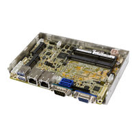
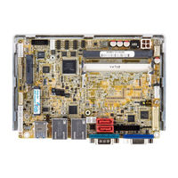
3.5" SBC supports Intel 22nm 4th/ 14nm 5th Generation Mobile Core i7/i5/i3 and Celeron on-board Processor (ULT), VGA/LVDS/iDP, Dual GbE, PCIe Mini, USB 3.0, SATA 6Gb/s Audio, iRIS-1010 and RoHS
Brand:
IEI Technology
| Category:
Single board computers
| Size: 10 MB
Table of Contents
Table of Contents
5
1 Introduction
16
Introduction
17
Benefits
17
Figure 1-1: WAFER-ULT/ULT2-I1
17
Model Variations
18
Features
18
Table 1-1: Model Variations
18
Connectors
19
Figure 1-2: Connectors
19
Dimensions
20
Figure 1-3: WAFER-ULT/ULT2-I1 Dimensions (MM)
21
Data Flow
22
Figure 1-4: Data Flow Diagram
22
Technical Specifications
23
Table 1-2: WAFER-ULT/ULT2-I1 Specifications
25
2 Packing List
26
Anti-Static Precautions
27
Unpacking Precautions
27
Packing List
28
Optional Items
29
Table 2-1: Packing List
29
Table 2-2: Optional Items
30
3 Connectors
31
Peripheral Interface Connectors
32
WAFER-ULT/ULT2-I1 Layout
32
Figure 3-1: Peripheral Interface Connectors
32
Peripheral Interface Connectors
33
External Interface Panel Connectors
34
Internal Peripheral Connectors
34
Table 3-1: Peripheral Interface Connectors
34
Table 3-2: External Peripheral Connectors
34
Figure 3-2: Power Connector Location
35
Power Connector
35
Table 3-3: Power Connector Pinouts
35
Audio Connector
36
Figure 3-3: 5 V SATA Power Connector Locations
36
SATA Power Connectors
36
Table 3-4: 5 V SATA Power Connector Pinouts
36
Battery Connector
37
Figure 3-4: Audio Connector Location
37
Table 3-5: Audio Connector Pinouts
37
Buzzer Connector
38
Figure 3-5: Battery Connector Location
38
Table 3-6: Battery Connector Pinouts
38
Chassis Intrusion Connector
39
Figure 3-6: Buzzer Connector Location
39
Figure 3-7: Chassis Intrusion Connector Location
39
Table 3-7: Buzzer Connector Pinouts
39
Digital I/O Connector
40
Figure 3-8: Digital I/O Connector Location
40
Table 3-8: Chassis Intrusion Connector Pinouts
40
EC Debug Connector
41
Figure 3-9: EC Debug Connector Location
41
Table 3-10: EC Debug Connector Pinouts
41
Table 3-9: Digital I/O Connector Pinouts
41
Figure 3-10: Internal Displayport Connector Location
42
Internal Displayport Connector
42
Table 3-11: Internal Displayport Connector Pinouts
42
Figure 3-11: IPMI LED Connector Location
43
IPMI LED Connector
43
Iris Module Slot
43
Table 3-12: IPMI LED Connector Pinouts
43
Figure 3-12: Iris Module Slot Location
44
Keyboard and Mouse Connector
44
Figure 3-13: Keyboard and Mouse Connector Location
45
Table 3-13: Keyboard and Mouse Connector Pinouts
45
Figure 3-14: LAN LED Connector Locations
46
LAN LED Connectors
46
LVDS Backlight Control Connector
46
Table 3-14: LAN LED Connector Pinouts
46
Figure 3-15: LVDS Backlight Control Connector Location
47
LVDS Connector
47
Table 3-15: LVDS Backlight Control Connector Pinouts
47
Figure 3-16: LVDS Connector Location
48
Table 3-16: LVDS Connector Pinouts
48
Figure 3-17: Pcie Mini Card Slot Location
49
Pcie Mini Card Slot
49
Power and HDD LED Connector
50
Table 3-17: Pcie Mini Card Slot Pinouts
50
Figure 3-18: Power and HDD LED Connector Location
51
Power Button Connector
51
Table 3-18: Power and HDD LED Connector Pinouts
51
Figure 3-19: Power Button Connector Location
52
Figure 3-20: Reset Button Connector Location
52
Reset Button Connector
52
Table 3-19: Power Button Connector Pinouts
52
Figure 3-21: SATA 6Gb/S Connector Locations
53
SATA 6Gb/S Connectors
53
Table 3-20: Reset Button Connector Pinouts
53
Figure 3-22: RS-232 Serial Port Connector Locations
54
Serial Port Connector, RS-232
54
Table 3-21: SATA 6Gb/S Drive Connector Pinouts
54
Figure 3-23: RS-422/485 Serial Port Connector Location
55
Serial Port Connector, RS-422/485
55
Table 3-22: RS-232 Serial Port Connector Pinouts
55
Table 3-23: RS-422/485 Serial Port Connector Pinouts
55
Figure 3-24: Smbus Connector Location
56
Smbus Connector
56
Table 3-24: DB-9 RS-422/485 Pinouts
56
Figure 3-25: SO-DIMM Slot Locations
57
SO-DIMM Slots
57
Table 3-25: Smbus Connector Pinouts
57
Figure 3-26: SPI Flash Connector Location
58
SPI Flash Connector
58
System Fan Connector
58
Table 3-26: SPI Flash Connector Pinouts
58
Figure 3-27: System Fan Connector Location
59
Table 3-27: System Fan Connector Pinouts
59
USB 2.0 Connector
59
External Interface Connectors
60
Figure 3-28: USB 2.0 Connector Location
60
Figure 3-29: External Interface Connectors
60
Table 3-28: USB 2.0 Connector Pinouts
60
Ethernet Connectors
61
Figure 3-30: LAN Connector
61
Table 3-29: LAN Pinouts
61
USB 3.0 Ports
61
Figure 3-31: Serial Port
62
Serial Port Connector (COM1)
62
Table 3-30: USB 3.0 Port Pinouts
62
Table 3-31: Serial Port Pinouts
62
Figure 3-32: VGA Connector
63
Table 3-32: VGA Connector Pinouts
63
VGA Connector
63
4 Installation
64
Anti-Static Precautions
65
Installation Considerations
65
So-DIMM Installation
67
Iris-1010 Module Installation
67
Figure 4-1: SO-DIMM Installation
67
Figure 4-2: Removing the Retention Screw for the Iris-1010 Module
68
Figure 4-3: Inserting the Iris-1010 Module into the Slot at an Angle
68
Full-Size Pcie Mini Card Installation
69
Figure 4-4: Securing the Iris-1010 Module
69
Figure 4-5: Removing the Retention Screw
70
Figure 4-6: Inserting the Full-Size Pcie Mini Card into the Slot at an Angle
70
Half-Size Pcie Mini Card Installation
71
Figure 4-7: Securing the Full-Size Pcie Mini Card
71
Figure 4-8: Removing the Standoff
72
Figure 4-9: Installing the Standoff
72
System Configuration
73
Figure 4-10: Inserting the Half-Size Pcie Mini Card into the Slot at an Angle
73
Figure 4-11: Securing the Half-Size Pcie Mini Card
73
DC 5V Jumper for LVDS Backlight Dimming
74
Figure 4-12: DC 5V Jumper Location
74
Table 4-1: DC 5V Jumper Settings
74
Table 4-2: DC 5V Jumper Pinouts
74
AT/ATX Power Mode Selection
75
Clear CMOS Button
75
Figure 4-13: AT/ATX Power Mode Switch Location
75
Figure 4-14: Clear CMOS Button Location
75
Table 4-3: AT/ATX Power Mode Switch Settings
75
Figure 4-15: LVDS Panel Type Selection Switch Location
76
LVDS Panel Type Selection
76
Table 4-4: LVDS Panel Type Selection
76
Figure 4-16: LVDS Voltage Selection Jumper Location
77
LVDS Voltage Selection
77
Table 4-5: LVDS Voltage Selection Jumper Settings
77
Chassis Installation
78
Heat Sink Enclosure
78
Figure 4-17: Heat Sink Retention Screws
78
Motherboard Installation
79
Figure 4-18: Motherboard Installation Example
79
Internal Peripheral Device Connections
80
AT/ATX Power Connection
80
Figure 4-19: Power Cable to Motherboard Connection
80
Audio Kit Installation
81
Figure 4-20: Connect Power Cable to Power Supply
81
LVDS LCD Installation
82
Figure 4-21: Audio Kit Cable Connection
82
Figure 4-22: LVDS Connector
83
SATA Drive Connection
84
Figure 4-23: Backlight Inverter Connection
84
USB Cable Installation
85
Figure 4-24: SATA Drive Cable Connection
85
Intel ® Amt Setup Procedure
86
Figure 4-25: Dual-Port USB Cable Connection
86
Ipmi Setup Procedure
87
Managed System Hardware Setup
87
5 Bios
88
Introduction
89
Starting Setup
89
Using Setup
89
Getting Help
90
Unable to Reboot after Configuration Changes
90
BIOS Menu Bar
90
Table 5-1: BIOS Navigation Keys
90
Main
91
BIOS Menu 1: Main
91
Advanced
92
BIOS Menu 2: Advanced
92
BIOS Menu 3: CPU Configuration
93
CPU Configuration
93
ACPI Settings
95
BIOS Menu 4: ACPI Settings
95
AMT Configuration
96
BIOS Menu 5: AMT Configuration
96
F81866 Super IO Configuration
97
Serial Port N Configuration
97
BIOS Menu 6: F81866 Super IO Configuration
97
BIOS Menu 7: Serial Port N Configuration Menu
97
Iwdd H/W Monitor
102
Smart Fan Mode Configuration
102
BIOS Menu 8: Iwdd H/W Monitor
102
BIOS Menu 9: Smart Fan Mode Configuration
102
RTC Wake Settings
103
BIOS Menu 10: RTC Wake Settings
104
BIOS Menu 11: Serial Port Console Redirection
105
Serial Port Console Redirection
105
BIOS Menu 12: SATA Configuration
108
SATA Configuration
108
BIOS Menu 13: Intel(R) Rapid Start Technology
109
Intel(R) Rapid Start Technology
109
BIOS Menu 14: USB Configuration
110
USB Configuration
110
BIOS Menu 15: Iei Feature
111
Iei Feature
111
Chipset
112
System Agent (SA) Configuration
112
BIOS Menu 16: Chipset
112
BIOS Menu 17: System Agent (SA) Configuration
112
BIOS Menu 18: Graphics Configuration
113
Graphics Configuration
113
BIOS Menu 19: LCD Control
114
Memory Configuration
116
PCH-IO Configuration
116
BIOS Menu 20: Memory Configuration
116
BIOS Menu 21: PCH-IO Configuration
116
BIOS Menu 22: PCI Express Configuration
117
PCI Express Configuration
117
BIOS Menu 23: M_PCIE2 Configuration Menu
118
BIOS Menu 24: PCH Azalia Configuration
119
PCH Azalia Configuration
119
Security
120
BIOS Menu 25: Security
120
Boot
121
BIOS Menu 26: Boot
121
Save & Exit
123
BIOS Menu 27: Save & Exit
123
Server Mgmt
124
System Event Log
124
BIOS Menu 28: Server Mgmt
124
BIOS Menu 29: System Event Log
124
BMC Network Configuration
126
BIOS Menu 30: System Event Log
126
6 Software Drivers
127
Available Software Drivers
128
Software Installation
128
Chipset Driver Installation
129
Figure 6-1: Chipset Driver Welcome Screen
129
Figure 6-2: Chipset Driver License Agreement
130
Figure 6-3: Chipset Driver Read Me File
130
Figure 6-4: Chipset Driver Setup Operations
131
Figure 6-5: Chipset Driver Installation Finish Screen
131
Graphics Driver Installation
132
Figure 6-6: Graphics Driver Welcome Screen
132
Figure 6-7: Graphics Driver License Agreement
133
Figure 6-8: Graphics Driver Read Me File
133
Figure 6-9: Graphics Driver Setup Operations
134
Figure 6-10: Graphics Driver Installation Finish Screen
134
Lan Driver Installation
135
Figure 6-11: Intel® Network Connection Menu
135
Figure 6-12: LAN Driver Welcome Screen
136
Figure 6-13: LAN Driver License Agreement
136
Figure 6-14: LAN Driver Setup Options
137
Figure 6-15: LAN Driver Installation
138
Figure 6-16: LAN Driver Installation Complete
138
Audio Driver Installation
139
Figure 6-17: Installshield Wizard Welcome Screen
139
Figure 6-18: Audio Driver Software Configuration
140
Figure 6-19: Restart the Computer
140
Usb 3.0 Driver Installation
141
Figure 6-20: USB 3.0 Driver Welcome Screen
141
Figure 6-21: USB 3.0 Driver License Agreement
142
Figure 6-22: USB 3.0 Driver Read Me File
142
Figure 6-23: USB 3.0 Driver Setup Operations
143
Figure 6-24: USB 3.0 Driver Installation Finish Screen
143
Intel® AMT Driver Installation
144
Figure 6-25: Intel® ME Driver Welcome Screen
144
Figure 6-26: Intel® ME Driver License Agreement
145
Figure 6-27: Intel® ME Driver Setup Operations
146
Figure 6-28: Intel® ME Driver Installation Finish Screen
146
A Regulatory Compliance
147
BBIOS Options
149
C Terminology
152
D Digital I/O Interface
156
Introduction
157
Assembly Language Sample
158
Assembly Language Sample 2
158
Watchdog Timer
159
Advertisement
IEI Technology WAFER-ULT2-i1 Quick Installation Manual (10 pages)
3.5" SBC supports Intel 22nm 4th/14nm 5th Generation Mobile Core i7/i5/i3 and Celeron on-board Processor ULT, VGA, LVDS, iDP, Dual GbE, PCIe Mini, USB 3.0, SATA 6Gb/s, Audio, iRIS-1010 and RoHS
Brand:
IEI Technology
| Category:
Single board computers
| Size: 0 MB
Table of Contents
Specifications
2
Ordering Information
5
Jumper Settings and Connectors
7
Board Layout: Jumper and Connector Locations
9
Advertisement
Related Products
IEI Technology WAFER-ULT-i1
IEI Technology WAFER-ULT5
IEI Technology WAFER-ULT5-i7-R10
IEI Technology WAFER-ULT5-i5-R10
IEI Technology WAFER-ULT5-i3-R10
IEI Technology WAFER-ULT5-C-R10
IEI Technology WAFER-JL-N5105
IEI Technology WAFER-9371A
IEI Technology WAFER-EHL2
IEI Technology WAFER-RK3568-A-R10
IEI Technology Categories
Motherboard
Touch Panel
Computer Hardware
Single board computers
Desktop
More IEI Technology Manuals
Login
Sign In
OR
Sign in with Facebook
Sign in with Google
Upload manual
Upload from disk
Upload from URL