Sign In
Upload
Manuals
Brands
Husky Manuals
Controller
Altanium Matrix5
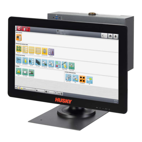
Husky Altanium Matrix5 Manuals
Manuals and User Guides for Husky Altanium Matrix5. We have
2
Husky Altanium Matrix5 manuals available for free PDF download: User Manual
Husky Altanium Matrix5 User Manual (336 pages)
Brand:
Husky
| Category:
Control Unit
| Size: 7 MB
Table of Contents
General Information
3
Husky Regional Service and Sales Offices
3
Ordering Spare Parts
3
Product Upgrades
3
Telephone Support Numbers
3
Ordering Additional Manuals
4
Table of Contents
5
General Safety
15
Introduction
15
Safety Signs
16
Input Wiring (Conventional)
17
Purpose of the Equipment
17
Restrictions of Use
17
Environmental Operating Specifications
18
Equipment Ratings
18
Technical Specifications
18
Controller Lifting Instructions
19
Chapter 2 Hot Runner Temperature Control
23
Types of Temperature Control
23
Open Loop Control
23
Configuring Zones
23
Configure a Zone for Zero Cross Control
24
Configure a Zone for Phase Angle Control
24
Determine the Heater Size
24
Thermocouple Types and Color Codes
25
Chapter 3 Connect the System to the Mold
27
Before Startup
27
Connect to the Power Source
27
Startup Procedure Checklist
28
Chapter 4 Altanium Operator Interface
29
General
29
Altanium Operator Interface
29
Home Screen
30
Altanium Buttons
31
Controller Function Buttons
31
System Status Field
32
Navigation Buttons
32
Alarm Buttons
33
System and User Management Buttons
34
Dialog Window Buttons
35
System Modes
35
Servo Control
37
Temperature Control Views
37
Temperature Control
38
Common Buttons
39
System Configuration Buttons
40
Screen Keyboards, Keypads, and Selection Menus
40
Keypad Use
41
Enter a Specified Setpoint Value
42
Increase or Decrease a Setpoint by a Specified Value
42
Select a Language
43
Print to a File
44
Print Report Descriptions
45
Online Help
47
Chapter 5 Security and Administration
49
User Management and Security Screens
49
Set User Roles
49
Set Screen Security
51
Screen Security - Main 1 Screen
52
Screen Security - Main 2 Screen
54
Screen Security - Heats Page 1 Screen
54
Screen Security - Heats Page 2 Screen
57
Screen Security - Servo Screen
58
User Preferences
59
Auto Logout
59
Mold Setups
61
Files Screen
61
Make a New Mold Setup Folder
63
Make a New Mold Setup File
64
Save Changes to a Mold Setup File
64
Discard Changes to a Mold Setup File
64
Save the Current Mold Setup File as a New File
65
Load an Existing Mold Setup File
65
Delete Files
65
Copy Files
65
Rename Files
66
Transfer Data to the Network
66
Transfer Data with a USB Storage Device
66
Chapter 7 Making Adjustments
67
Zone Selection
67
Make a Zone Group
68
Multi Group View Screen
69
Changing the Header Color
71
Graphical View Screen
72
Neo View Screen
75
Simple Screen Mode
75
Detailed Screen Mode
76
Zone Block Background Color
78
Follower Zone Block
79
Status Abbreviations
79
Text View Screen
80
Zone Selection in the Text View Screen
82
Sorting
82
Quick Adjustment Panel
83
Quick Set Screen
84
Zone Setpoint Fields
84
Frequently Used
84
Zone Edit
85
Setpoint Limits
86
Manual Standby
86
Manual Boost
87
Remote Standby
87
Remote Boost
88
Advanced Settings
88
Control Settings
89
Zone Name
90
Multiple Zones Names
91
Temperature Setpoints
92
Alarm Window
92
Abort Window
92
Output Mode
93
Zone Follow
93
Automatic Follow Function
93
Manually Assign One Zone (Follower) to a Another Zone (Leader)
94
Regulation Mode
94
Setpoint Limits
95
Change the Normal Setpoint and Limits
95
Change the Manual Standby and Remote Standby Setpoint Limits
95
Change the Manual Standby Setpoint Limits
96
Change the Remote Standby Setpoint Limits
96
Change the Manual Boost Setpoints and Limits
96
Change the Remote Boost Setpoints and Limits
97
Change the Sensor Assignment (Thermocouple)
98
Change the Priority Control Mode
98
Change the Earth Leakage Check
99
Change the Automatic Manual Control
99
Change the Output Power Limit Setting
99
Change the Zone Control from ART to PID
100
Change P, I or D Parameter Values
100
Active Reasoning Technology
101
ART Process Screen
101
Manual ART Function
103
Art 2.0
104
PID Control
106
Typical PID Values
106
Possible Causes of Oscillation
106
Chapter 8: Mold Diagnostics
107
Testing the Mold
107
Run a Mold Diagnostics Test
109
Set the Zone Cooling Time
109
Set the Maximum Test Time
110
Diagnostics Results
110
Test Results Screen Values
111
Automatic Thermocouple Rewiring
113
Cross Talk Screen
113
Temperature Graphs Screen
114
Chapter 9 Heat the Mold
117
Heater Circuit Test
117
Startup
117
Earth Leakage/Wet Heater Bake out System
118
Earth Leakage Limit
118
Set the Earth Leakage Limit
118
Configure the Length and Number of Bake out Cycles
119
Altastart
119
Unistart
120
Fast Heating
120
Soft Start
121
Enable Soft Start
121
Disable Soft Start
121
Adjust the Soft Start Minimum Limit
122
Alarms Screen
122
Open the Alarms Screen
123
Alarm States
123
Clear Alarms
124
Event History Screen
124
Filter Events
125
Alarm and Event Icons
126
Alarm Conditions - Warning Errors
127
Abort Conditions - Shutdown Errors
128
Chapter 10 System Setup
131
System Setup - Main Settings
132
System Setup - Network Settings
134
Wired Network
134
Wireless Network
135
Network Share
137
Dashboard Interface
139
Remote Service Assistance
139
Proxy Settings
139
Start a Teamviewer Session
140
Virtual Network Computing
141
VNC Client
142
VNC Server
142
VNC Connection
142
OPC UA Interface
144
OPC UA Interface Enable
144
Certificates
145
Shotscopenx
147
Network Diagnostics
148
Time Synchronization
149
System Setup - Heats Settings
151
Heats Setup - Control
151
Heats Setup - Control
154
Heats Setup - Control
156
Heats Setup - Monitoring
157
Force Temperature Units to Option
161
Units of Measure
161
Equipment Protection
161
Power Conservation
162
Part Counting
162
Set Part Counting
162
Reset the Part Counter
163
Sack Full Output Optimization
163
Remote Load
165
Grid Size and the Group Offset
167
Zone Alarm Control
167
Monitor Zone Settings
168
Power Limiting
168
Power Deviation
168
Current Deviation
170
No Heater Detection
170
Energy Usage and Units
171
Number of Zones in the System
171
Standby Timer Settings
172
Set the Manual Standby Duration Timer
172
Set the Remote Standby Duration Timer
173
Set the Remote Standby Delay Timer
173
Set the Remote Standby Input Mode
174
Standby Operation Description
174
Boost Timer Settings
176
Set the Manual Boost Duration Timer
176
Set the Remote Boost Duration Timer
176
Set the Remote Boost Delay Timer
176
Change the Remote Boost Input Mode
177
Boost Operation Description
177
Resin Protection Timer
178
Set the Resin Degradation Limit
179
Set the Cycle Idle Time Limit
179
Set the Cycle Idle Reaction
179
Auto Power Limiting
180
Options and Licensing
180
Diagnostics Export
181
Mold Cooling Enable
182
Staged Startup and Shutdown
182
Staging Screen
182
Enable/Disable Staged Startup
184
Enable or Disable Staged Shutdown
185
Set the Staged Temperature and Power Setpoints
185
Hold a Stage Setpoint
185
Set the Soak Timers
186
Supply Voltage Screen
186
Configure the Supply Voltage
189
Chapter 11 Mold Picture View
191
Mold Picture View Graphic
191
Map a Network Drive
191
Load a Mold Picture View Graphic
192
Mold Picture View Toolbar
194
Configure a Mold Picture View
195
Edit Mode
195
Zone Information Panels
195
Make a Zone Information Panel
196
Move a Zone Information Panel
196
Edit a Zone Information Panel
197
Make a Leader Line
198
Change the Color of a Leader Line
198
Change the Thickness of a Leader Line
198
Delete a Leader Line
199
Delete a Zone Information Panel
199
Exit Edit Mode
199
Chapter 12 Data Recording
201
Trend Plot Screen
201
Set the Trend Plot
201
History Plot Screen
203
Curve Data Point
204
Set the Timeframe
205
Set the Date and Time Range
205
Change the Date and Time Range Old
205
Change the Date and Time Range New
205
Change the Zone Shown on the History Plot Screen
206
Process Limits Screen
207
Target Settings
208
Global Settings
209
Delay Limit Check
209
Process Variable Selector
210
Process Monitoring Setup
211
Time Mode Configuration
211
Cooldown Data Collection
212
Cycle Mode Configuration
212
Data Collection Start Conditions
213
Data Collection Stop Conditions
214
Cycle Input (Heat Control Only)
221
Process Monitoring Status
221
Process Log Transfer
221
Process Data Filter
221
Save Process Data Setup
222
Chapter 13 Color Change
225
Color Change Screen
226
Ultra Purge Settings Panel
227
Ultra Purge Sequence Panel
227
Ultra Purge Mode Buttons and Status
228
Color Change Settings Panel
228
Cycle Input Connection
229
Start the Ultra Purge Process
229
Ultra Purge Process Sequences
230
Color Change and Non-Thermal Sensitive Resin
230
Color Change and Non-Thermal Sensitive Resin Example
231
Color Change and Thermal Sensitive Resin
237
Color Change and Thermal Sensitive Resin Example
237
No Color Change
243
No Color Change Example
244
Chapter 14 System Options
251
Digital I/O
251
Enable an I/O Option
252
Safety Signals (Ultrasync-E or Altanium Servo Control Installed)
252
Digital Inputs
253
Servo Digital Inputs
253
Heats Digital Inputs
254
Digital Outputs
256
Servo Digital Outputs
256
Heats Digital Outputs
259
Configurable Signals
261
Sequencer Installed)
261
Logic Function
262
Force
263
Conditions
263
Cable Connections
263
Input/Output Connector Pin-Out Description
265
Input Base Connector ID
265
Output Base Connector ID
265
Part Count Base Connector ID
267
Remote Load Base Connector ID
267
Chapter 15 SPI Protocol Option
269
SPI Command Summary
269
Echo
269
Process Setpoint
270
Process Value
270
Alarm Active Status
270
Alarm 1 Setpoint
271
Alarm 2 Setpoint
271
Alarm 1 Reset
271
Controller Status
272
Manual Percent Output
273
Open/Closed Loop
273
Chapter 16 Maintenance
275
Matrix5 System
275
Card Layout Screen
277
Troubleshooting with the Card Layout Screen
278
Intelligent Control Cards
280
Replace an Intelligent Control Card (ICC2 or ICC3)
282
Replace an Open Fuse on an Intelligent Control Card
284
Matrix5 Operator Interface
286
Remove and Replace the Touch Monitor
288
Remove and Replace the MCU
293
Remove and Replace the Operator Interface
296
Install the Remote Operator Interface
299
Install the Alternative Mounted Operator Interface
304
Install the Dual Touch Monitor
308
Thermocouple Calibration
314
Clean the System
317
Cabinet (Mainframe)
317
Touch Monitor
317
Basic Troubleshooting
318
Troubleshooting Procedures
318
Failure Causes and Solutions
321
Supported Electrical Failures
322
Appendix A Glossary of Terms
325
Index
327
Advertisement
Husky Altanium Matrix5 User Manual (248 pages)
Brand:
Husky
| Category:
Controller
| Size: 7 MB
Table of Contents
General Information
3
Telephone Support Numbers
3
Husky Regional Service and Sales Offices
3
Product Upgrades
3
Ordering Spare Parts
3
Ordering Additional Manuals
4
Table of Contents
5
Chapter 1 Introduction
13
General Safety
13
Safety Signs
14
Purpose of the Equipment
15
Restrictions of Use
15
Input Wiring (Conventional)
15
Environmental Operating Specifications
16
Equipment Ratings
16
Technical Specifications
16
Controller Lifting Instructions
17
Chapter 2 Hot Runner Temperature Control
21
Types of Temperature Control
21
Open Loop Control
21
Configuring Zones
21
Configure a Zone for Zero Cross Control
22
Configure a Zone for Phase Angle Control
22
Determine the Heater Size
22
Thermocouple Types and Color Codes
23
Chapter 3 Connect the System to the Mold
25
Before Startup
25
Connect to the Power Source
25
Startup Procedure Checklist
26
Chapter 4 Altanium Operator Interface
27
General Layout
27
Altanium Operator Interface
27
Home Screen
27
Altanium Buttons
28
Controller Function Buttons
28
System Status Field
29
Alarm Buttons
30
Navigation Buttons
30
System and User Management Buttons
31
Dialog Window Buttons
32
System Modes
32
Servo Control
34
Temperature Control Views
35
Temperature Control
36
Common Buttons
37
System Configuration Buttons
38
Select a Language
39
Print to a File
40
Print Report Descriptions
41
Online Help
43
Chapter 5 Security and Administration
45
User Management and Security Screens
45
Set User Roles
45
Set Screen Security
47
Screen Security - Main Screen
47
Screen Security - Heats Page 1 Screen
49
Screen Security - Heats Page 2 Screen
52
Screen Security - Servo Screen
53
User Preferences
54
Auto Logout
54
Chapter 6 Mold Setups
57
Mold Setup Screen
57
Make a New Mold Setup Folder
59
Make a New Mold Setup File
60
Save Changes to a Mold Setup File
60
Discard Changes to a Mold Setup File
60
Save the Current Mold Setup File as a New File
61
Load an Existing Mold Setup File
61
Delete Files
61
Copy Files
61
Rename Files
62
Transfer Data to the Network
62
Transfer Data with a USB Storage Device
62
Chapter 7 Making Adjustments
63
Zone Selection
63
Make a Zone Group
64
Multi Group View Screen
65
Changing the Header Color
67
Graphical View Screen Overview
68
Text View Screen Overview
71
Zone Selection in the Text View Screen
73
Sorting
73
Quick Set Screen
74
Zone Setpoint Fields
74
Frequently Used
74
Zone Edit
75
Manual Standby
76
Setpoint Limits
76
Manual Boost
77
Remote Standby
77
Advanced Settings
78
Remote Boost
78
Control Settings
79
Zone Name
80
Multiple Zones Names
80
Temperature Setpoints
81
Alarm Window
81
Abort Window
82
Output Mode
82
Zone Slave
82
Automatic Slave Function
83
Manually Slave One Zone to Another Zone
83
Regulation Mode
84
Setpoint Limits
84
Change the Normal Setpoint and Limits
84
Change the Manual Standby and Remote Standby Setpoint Limits
85
Change the Manual Standby Setpoint Limits
85
Change the Remote Standby Setpoint Limits
85
Change the Manual Boost Setpoints and Limits
86
Change the Remote Boost Setpoints and Limits
86
Change the Sensor Assignment (Thermocouple)
87
Change the Priority Control Mode
87
Change the Earth Leakage Check
88
Change the Automatic Manual Control
88
Change the Output Power Limit Setting
89
Change the Zone Control from ART to PID
89
Change P, I or D Parameter Values
89
Active Reasoning Technology (ART)
90
ART Process Screen
90
Manual ART Function
92
PID Control
93
Typical PID Values
93
Possible Causes of Oscillation
94
Chapter 8: Mold Diagnostics
95
Testing the Mold
95
Run a Mold Diagnostics Test
97
Set the Zone Cooling Time
97
Set the Maximum Test Time
98
Diagnostics Results
98
Test Results Screen Values
99
Automatic Thermocouple Rewiring
100
Cross-Talk Screen
101
Temperature Graphs Screen
102
Chapter 9 Heat the Mold
105
Heater Circuit Test
105
Startup
105
Earth Leakage/Wet Heater Bake out System
106
Earth Leakage Limit
106
Set the Earth Leakage Limit
106
Configure the Length and Number of Bake out Cycles
107
Soft Start
107
Enable Soft Start
108
Disable Soft Start
108
Adjust the Soft Start Minimum Limit
108
Alarms Screen
108
Open the Alarms Screen
110
Alarm States
110
Clear Alarms
110
Event History Screen
110
Filter Events
112
Alarm and Event Icons
113
Alarm Conditions - Warning Errors
113
Abort Conditions - Shutdown Errors
114
Chapter 10 System Setup
117
System Setup Screen
117
System Setup - Main
118
Network Screen
119
Connect to Network Share
120
Dashboard Interface
121
Shotscopenx
121
System Setup - Heats Setup
122
Heats Setup - Control
122
Heats Setup - Control
125
Heats Setup - Monitoring
127
Force Temperature Units to Option
130
Units of Measure
130
Equipment Protection
130
Power Conservation
131
Part Counting
131
Set Part Counting
131
Reset the Part Counter
132
Sack Full Output Optimization
132
Remote Load
134
Grid Size and the Group Offset
136
Zone Alarm Control
136
Monitor Zone Settings
137
Power Limiting
137
Power Deviation
137
Current Deviation
139
No Heater Detection
139
Energy Usage and Units
140
Number of Zones in the System
141
Standby Timer Settings
141
Set the Manual Standby Duration Timer
141
Set the Remote Standby Duration Timer
141
Set the Remote Standby Delay Timer
142
Set the Remote Standby Input Mode
142
Standby Operation Description
143
Boost Timer Settings
144
Set the Manual Boost Duration Timer
144
Set the Remote Boost Duration Timer
144
Set the Remote Boost Delay Timer
145
Change the Remote Boost Input Mode
145
Boost Operation Description
146
Resin Protection Timer
147
Set the Resin Degradation Limit
147
Set the Cycle Idle Time Limit
148
Set the Cycle Idle Reaction
148
Auto Power Limiting
148
Options and Licensing
149
Diagnostics Export
150
Mold Cooling Enable
150
Staged Startup and Shutdown
150
Staging Screen
151
Enable/Disable Staged Startup
152
Enable or Disable Staged Shutdown
153
Set the Staged Temperature and Power Setpoints
153
Hold a Stage Setpoint
153
Set the Soak Timers
154
Supply Voltage Screen
154
Configure the Supply Voltage
157
Chapter 11 Mold Picture View
159
Mold Picture View Graphic
159
Map a Network Drive
159
Load a Mold Picture View Graphic
160
Mold Picture View Toolbar
162
Configure a Mold Picture View
163
Edit Mode
163
Zone Information Panels
163
Make a Zone Information Panel
164
Move a Zone Information Panel
164
Edit a Zone Information Panel
165
Change the Color of a Leader Line
166
Change the Thickness of a Leader Line
166
Make a Leader Line
166
Delete a Leader Line
167
Delete a Zone Information Panel
167
Exit Edit Mode
167
Chapter 12 Data Recording
169
Trend Plot Screen
169
Set the Trend Plot
169
History Plot Screen
171
Curve Data Point
172
Set the Timeframe
173
Set the Date and Time Range
173
Change the Date and Time Range New
173
Change the Date and Time Range Old
173
Change the Zone Shown on the History Plot Screen
174
Process Limits Screen
175
Target Settings
176
Global Settings
177
Delay Limit Check
177
Process Variable Selector
178
Process Monitoring Setup
179
Time Mode Configuration
179
Cool down Data Collection
180
Cycle Mode Configuration
180
Data Collection Start Conditions
181
Data Collection Stop Conditions
181
Cycle Input (Heat Control Only)
186
Process Monitoring Status
187
Process Log Transfer
187
Process Data Filter
187
Chapter 13 System Options
189
Digital I/O
189
Enable an I/O Option
190
Safety Signals (Ultrasync-E or Altanium Servo Control Installed)
190
Digital Inputs
190
Digital Outputs
192
Configurable Signals
194
Sequencer Installed)
194
Conditions
195
Force
195
Logic Function
195
Cable Connections
196
Input/Output Connector Pin-Out Description
197
Input Base Connector ID
197
Output Base Connector ID
198
Part Count Base Connector ID
199
Remote Load Base Connector ID
199
Chapter 14 SPI Protocol Option
201
SPI Command Summary
201
Echo
201
Process Setpoint
202
Process Value
202
Alarm Active Status
202
Alarm 1 Setpoint
203
Alarm 2 Setpoint
203
Alarm 1 Reset
203
Controller Status
204
Manual Percent Output
205
Open/Closed Loop
205
Chapter 15 Maintenance
207
Matrix5 System
207
Card Layout Screen
209
Troubleshooting with the Card Layout Screen
209
Intelligent Control Cards
211
Replace an Intelligent Control Card (ICC2 or ICC3)
213
Replace an Open Fuse on an Intelligent Control Card
215
Matrix5 Operator Interface
217
Remove and Replace the Touch Monitor
218
Remove and Replace the MCU
222
Remove and Replace the Operator Interface
225
Install the Remote Operator Interface
227
Install the Alternative Mounted Operator Interface
231
Install the Dual Touch Monitor
235
Calibrate the Thermocouple Inputs
240
Clean the System
241
Cabinet (Mainframe)
241
Touch Monitor
241
Basic Troubleshooting
242
Failure Causes and Solutions
244
Supported Electrical Failures
246
Advertisement
Related Products
Husky Altanium Delta5
Husky Altanium VGSC
Husky Altanium ASC
Husky Altanium Matrix2
Husky MP2500
Husky MP180
Husky MIG140
Husky Altanium Neo2
Husky Altanium Delta3
Husky Altanium Neo5
Husky Categories
Tool Storage
Air Compressor
Indoor Furnishing
Automobile Accessories
Pressure Washer
More Husky Manuals
Login
Sign In
OR
Sign in with Facebook
Sign in with Google
Upload manual
Upload from disk
Upload from URL