Sign In
Upload
Manuals
Brands
Husky Manuals
Controller
Altanium VGSC
Husky Altanium VGSC Manuals
Manuals and User Guides for Husky Altanium VGSC. We have
1
Husky Altanium VGSC manual available for free PDF download: User Manual
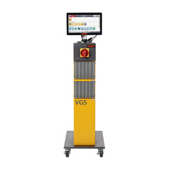
Husky Altanium VGSC User Manual (166 pages)
Valve Gate Sequencer Controller
Brand:
Husky
| Category:
Controller
| Size: 2 MB
Table of Contents
General Information
3
Husky Regional Service and Sales Offices
3
Ordering Additional Manuals
3
Ordering Spare Parts
3
Product Upgrades
3
Telephone Support Numbers
3
Table of Contents
5
Chapter 1 Introduction
11
Reference Directives and Standards
12
Safety
12
General Safety
13
Safety Signs on the Equipment
14
Equipment Function
15
Restrictions of Use
16
Input Wiring
16
Environmental Operating Specification
17
Equipment Ratings
17
Reference User Guides - Altanium Delta5 and Matrix5 User Guides
17
Temperature Controls
18
Temperature Control Views
18
Chapter 2 Integration
19
Limitations of this Manual
19
Reference Directive, Standards, and User Guides
19
Safety
20
VGSC Controls, Connectors, and Parts Identification
20
Initial Setup of the VGS Controller
21
Remove the VGSC from the Shipping Container
21
Lift the VGS Controller
21
General
21
Lift Procedures
22
Assemble the VGSC
25
Connect the Input Power
26
Overcurrent Protective Device
26
Bonding
27
Lockout/Tagout Procedures
27
2.10 Input/Output Signals and Other Connections
27
2.10.1 Injection Molding Machine Interface - X300 Connector
30
IMM Safety Gates Status - Pin 2
31
Enable Input - Pin 3
32
Software Configurable Inputs - Pins 4-9
32
Software Configurable Relay Outputs - Pins 17-24
32
2.10.2 Solenoid Outputs - X301 Connector
33
Screw Position Cable Potentiometer Analog Input - X302 Connector
36
(Optional)
36
2.10.4 Additional Analog Inputs - X303 Connector
38
2.10.5 Injection Molding Machine Interface - X304 Connector
41
2.10.6 Solenoid Outputs- X305 Connector
44
2.10.7 Ethercat Connection
46
2.10.8 Display Power and Temperature Control Connections
47
2.11 Start the VGS Controller
47
2.11.1 before You Apply Power
47
2.11.2 Apply Power to the VGSC
48
Chapter 3 Altanium VGSC Operator Interface
49
Operator Interface
49
Home Screen
50
Header/Footer Buttons and Indicators
51
Control Modes Buttons
51
Control Mode Change Permissions
52
Temperature Control Modes
53
System Status Field
54
System Modes (Integrated Temperature Control Systems)
54
Navigation Buttons
55
Alarm Buttons
56
System and User Management Buttons
57
System Screen Selections Buttons
58
Valve Gate Button
58
Common Buttons
59
System Configuration Buttons
59
Temperature Control Views (Integrated Systems)
60
Temperature Control Screens (Integrated Systems)
61
Dialog Window Buttons
62
Number Pads
63
Select a Language
64
Print to a File
64
Help
65
Security and Administration
67
Security Screens
67
Main Security Operations
68
Heats Security Operations (Integrated Systems)
71
Screen Security - Heats Page 1 Screen
71
Screen Security - Heats Page 2 Screen
73
Manage Users
75
Saved User Selections
76
Auto Logout
76
System Setup Screen
79
System Setup Main Screen
79
Select a Language
81
Set the Units of Measure
81
Network Settings
83
Heats Setup (Integrated System)
85
Temperature Control Configurations
85
Heats Setup - Control
86
Heats Setup - Control
89
Heats Setup - Control
90
Monitoring Configurations (Integrated System)
92
Valve Gate Sequencer Screens
97
VGS Home Screen
97
Curve Chart View and Adjustment Selections
98
Curve Selections
99
Sequence Screen
100
Linked Data Assemblies
101
Sequence
101
Data Sorts
101
Scale
102
Data Colors
102
Symbols
103
Error Message
103
Signals Screen
103
Start Triggers
105
Start Delay
107
Active Indicators
108
Manual Triggers
108
Packing Configuration
108
3-Stage, Two Triggers Packing Example
109
VGS Status
111
Multi-Select Screen
112
Valve Gate Groups
113
Options Screen
115
Input Signals
116
External at Temperature
116
VGS Start and End of Cycle
117
System State
117
Signal Configuration
117
Level
118
One Trigger
118
Two Triggers
119
Soak Timer
120
Cycle Timer
121
Packing
121
Group Names
122
Input/Output Screens
125
Digital Input Screens
126
VG Sequencer
127
Safety Signals
127
IMM Safety Gates Status
127
VGS Enable
128
Configurable Digital Inputs
128
Heat Screens
128
Digital Outputs Screens
129
VGS Solenoids Digital Outputs
130
VG Sequencer
130
Heats Digital Outputs
132
Analog Inputs
133
Analog Input Calibration
135
Configurable Signals
136
Logic Function
137
Force
137
Process Monitoring
139
Trend Plot Screen
139
Limits Screen
140
Process Variable Filter
142
History Plot Screen
143
Data Description
143
Timeframe Duration
144
Process History Time Range
144
Process History Scroll
145
Variable Selections
145
Setup Screen
146
Time Mode Configuration
149
Cooldown Data Collection
149
Cycle Mode Configuration
150
Appendix A Glossary of Terms
151
Appendix B Troubleshooting
153
Startup Troubleshooting
153
Q31 Circuit Breakers
154
VGS Controller Alarms
157
Fault Stop Immediate
157
Stop End of Cycle
158
Lost at Temperature
158
Output Signal State Error
158
Vgs Cycle Timeout Warning
158
Valve Stems Open Outside of Vgs Cycle Warning
159
Vgs Enable Input Is Low
159
Index
161
Advertisement
Advertisement
Related Products
Husky Altanium ASC
Husky ALF-C2
Husky ALF-C1
Husky ALF-C3
Husky ACR4896B
Husky ACR4896W-P
Husky AT18304-6B
Husky AT18503-10C
Husky AT18303P-4A
Husky AT18621P-16A
Husky Categories
Tool Storage
Air Compressor
Indoor Furnishing
Automobile Accessories
Pressure Washer
More Husky Manuals
Login
Sign In
OR
Sign in with Facebook
Sign in with Google
Upload manual
Upload from disk
Upload from URL