Sign In
Upload
Manuals
Brands
HP Manuals
Desktop
Model 745 - VME Workstation
HP Model 745 - VME Workstation Manuals
Manuals and User Guides for HP Model 745 - VME Workstation. We have
9
HP Model 745 - VME Workstation manuals available for free PDF download: Owner's Manual, Handbook, Manual, Installation, Declaration Of Conformity
HP Model 745 - VME Workstation Owner's Manual (220 pages)
Model 745 Industrial Controller Owner's Guide
Brand:
HP
| Category:
Desktop
| Size: 5.91 MB
Table of Contents
Table of Contents
3
Related Manuals Preface-II
14
Revision History
15
Documentation Conventions Preface-IV
16
Questions, Suggestions, or Problems Preface-V
17
1 Product Description
19
The Model 745 Industrial Controller
21
Model 745 Front View
21
Model 745 Rear View
22
Board Computer Front Panel
22
Features
23
Physical Dimensions and Power Requirements
25
Board Computer Configurations
26
Cables
27
Cabling
27
Environmental Requirements
28
Operating System Overview
29
Manuals for System Information
30
Online Sources of Information
31
Audio
32
2 Connecting Cables
33
Introduction
35
Model 745 Front Panel Connectors
35
Connecting a Monitor or Text-Only Terminal
36
Configuration Requirements
36
Connecting the Monitor
36
Monitor Power Cord
37
Connecting a Monitor
37
Connecting a Terminal
39
Connecting a Terminal to the RS-232 Ports
39
Audio Connection
40
Audio Specifications
41
Audio Connector
42
Audio Connector Pinouts
42
Video Connection
43
Video Connector
43
Video Connector Pins and Signals
43
Keyboard and Mouse Connections
44
PS/2 Connector
44
SCSI Connections
45
SCSI Cable
45
SCSI Connector
46
SCSI Connector Pinouts
47
Network Connection
48
AUI LAN Connector
48
AUI LAN Connector Pinouts
49
Printer Connections
50
Preparing for HP-UX Installation
50
Configuring HP-UX for a Printer
50
Installation Procedure
51
Testing the Printer Installation
53
HP Parallel
53
HP Parallel Connector
54
HP Parallel Connector Pinouts
54
RS-232 Port a
55
RS-232 Serial Connector
55
RS-232-C Connector Pinouts
55
3 Power-On/Power-Off
57
Powering on the System
59
Power Supply Connector and Rear Switch
61
Front Power Switch
62
Powering off the System
63
Using SAM to Stop the HP-UX System
64
Using the Command Line
64
4 Processor Options Installation
65
Tools Required and Preliminary Procedures
67
Tools Required for Installation
67
Preliminary Procedures
67
Safety Precautions
68
Removing the Processor Board
69
Removing the Board Computer Assembly
69
Memory
70
Preliminary Requirements
70
RAM Card Installation
70
Installing RAM Cards
70
RAM Card Removal
71
PMC Bridge Adapter and Expansion Adapter
72
Preliminary Requirements
72
PMC Bridge Adapter and Expansion Adapter Installation
72
Installing a PMC Card Onto the Bridge Adapter
72
Installing a PMC Card Onto the Expansion Adapter
74
Removing Bridge Adapter Screws
75
Installing the Expansion Adapter Onto the Bridge Adapter
76
Installing the PMC Bridge Adapter Onto the Board Computer
77
Removing Ejector Handle Labels
79
Installing Ejector Handle Sleeves
80
Installing the Springs and Labels
81
Installing the Board Computer with PMC into Chassis
82
5 EISA Card Installation
85
EISA Accessory Card Configuration Files
87
Hardware Installation
88
Tools Required
88
Procedure
88
Removing the Top Cover
89
Blank Slot Plate and Screw
90
Installing the EISA Card and Screw
90
6 PCI Card Installation
93
Hardware Installation
95
Tools Required
95
Procedure
95
Installing the PCI Card and Screw
98
7 Installing and Configuring Mass Storage Devices
101
Hardware Installation for Drives
103
Supported Mass Storage Devices
103
Module Orientations
104
Mass Storage Module: Typical Device Positions
104
Finding the Status of Existing SCSI Bus Addresses
105
Installing Mass Storage Devices
106
Removing Retainer Bracket
106
Installing a Device in a Mass Storage Carrier
108
Device Installation in the Disk Carrier
109
Installing the 3.5-Inch Adapter Brackets
110
Inch Hard Disk Installation with Filler Panel
111
Disk Carrier and Filler Panels
112
Installing the Disk Carriers
113
Replacing Retainer Bracket
114
Configuring for a Hard Disk Drive
115
Software Installation of the Hard Disk Drive Upgrade
115
8 Using Mass Storage Devices
119
Using Your CD-ROM Drive
120
CD-ROM Drive and CD-ROM Media Descriptions
121
CD-ROM Drive
121
CD-ROM Drive Controls and Features
121
CD-ROM Media
122
CD-ROM Controls and Features
122
Operating the CD-ROM Drive
124
Loading and Unloading a CD-ROM in the Disc Tray
124
CD-ROM Disc Tray
124
Placing a CD-ROM Disc in a Drive
125
Removing a CD-ROM Disc from a Drive
126
Verifying the CD-ROM Drive Operation
127
Mounting and Unmounting a CD-ROM Disc
129
Mounting a CD-ROM Disc Using SAM
129
Unmounting a CD-ROM Disc Using SAM
131
Reading the Busy Light
132
DDS Tape Drive and Data Cassette Descriptions
133
DDS Drive
133
DDS Tape Drive Capacities Without Data Compression
134
DDS Tape Drive Capacities with Data Compression
134
Tape Drive Controls and Indicators
135
Tape Drive LED Display Codes
135
Data Cassettes
137
Setting the Write-Protect Tab on a Data Cassette
138
Setting the Write-Protect Tab on a DDS Tape
139
Operating the DDS Tape Drive
140
Loading and Unloading a Data Cassette
140
Verifying the DDS Tape Drive Operation
141
Using Device Files
141
Archiving Data
142
Writing to a Data Cassette
142
Restoring Files from a Data Cassette to Your System
143
Listing the Files on a Data Cassette
143
Further Command Information
143
Ordering Information
145
Using the Floppy Diskette
146
Setting the Write-Protect Tab on a Diskette
146
Setting the Write-Protect Tab on a Floppy Diskette
146
Inserting and Removing a Diskette
147
Inserting and Removing a Floppy Diskette
147
Operating the Floppy Drive
148
Verifying the Floppy Drive Configuration
148
Using Device Files
148
Formatting a New Diskette
149
Transferring Data to and from a Floppy Diskette
149
Saving Files to a Floppy Diskette
150
Restoring Files from a Floppy Diskette to Your System
150
Listing the Files on a Floppy Diskette
151
For more Information
151
Configuring the Floppy Driver
152
Ordering Information
153
9 Dealing with Problems
155
Interpreting the Leds
157
Model 745 LED Location
157
LED Indicators
158
Managing a Boot Failure
159
Boot Program Initializes Hardware
159
Recovering from a System Panic
160
Summary of Possible Causes of Panics Problem Area and Action
161
Procedures for Recovering from a System Panic
162
System Panic Procedures
162
Dealing with Network Failures
166
Problems with the Network
166
Configuring the HP-UX Kernel
167
Declaration of Conformity
170
Emissions Regulations and Statements
172
Federal Communications Commission (FCC
172
VCCI Class a ITE
173
Taiwan BCIQ Class a
173
Emissions Regulations Compliance
174
Acoustics
175
Regulation on Noise Declaration for Machines -3. GSGV
175
Electrostatic Discharge (ESD) Precautions
176
Safety Statement
177
Laser Safety Statement
178
Warnings and Cautions
179
The Boot Console Interface
181
Boot Console User Interface Features
182
Main Menu
183
Configuration Menu
184
Information Menu
185
Service Menu
185
Accessing the Boot Console Interface
186
Booting Your Workstation
188
Searching for Bootable Media
190
Restoring the Factory Default Configuration
191
Displaying and Setting Paths
192
System Paths
192
Mnemonic Style Notation
193
Displaying and Setting the Monitor Type
195
The Monitor Command
195
Displaying the Current Monitor Configuration
196
Setting the Monitor Type
197
Setting the Monitor Type at Power on
199
Using the Emergency Interactive Console Search
200
Displaying the Current Memory Configuration
202
Memory Information Example
202
Displaying the Status of the System I/O
204
Setting the Auto Boot and Auto Search and Auto Start Flags
205
Displaying and Setting the Security Mode
207
Displaying and Setting the Fastboot Mode
208
Displaying the LAN Station Address
209
Displaying System Information
210
Displaying PIM Information
211
Advertisement
HP Model 745 - VME Workstation Handbook (170 pages)
HP Model 745 Service Handbook
Brand:
HP
| Category:
Desktop
| Size: 5.22 MB
Table of Contents
Service Handbook
1
Safety and Regulatory Statements
3
Table of Contents
5
1 Product Information
15
The Model 745 Industrial Controller
17
Model 745 Front View
17
Model 745 Rear View
18
Board Computer Front Panel
18
Features
19
Typical External Devices
20
Physical Dimensions and Power Requirements
21
Board Computer Configurations
22
Cables
23
Cabling
23
Operating System Overview
24
Manuals for System Information
25
Hp-Ux
25
Hp Vue
25
Hp Cde
25
Online Sources of Information
26
Audio
27
Product Identification
28
Support
28
Hardware Support
28
Field Repair Philosophy
28
Serial Number Information
28
2 Environmental/Installation/Pm
31
Overview
32
Environmental Specifications
33
Environmental Information
33
Regulatory Requirements
34
Regulatory Information
34
Installation
35
Preventive Maintenance
36
3 Configuration
37
Boot Console User Interface Features
38
Main Menu
39
Configuration Menu
40
Information Menu
41
Service Menu
42
Accessing the Boot Console Interface
43
Booting Your Workstation
45
Searching for Bootable Media
47
Restoring the Factory Default Configuration
48
Displaying and Setting Paths
49
System Paths
49
Mnemonic Style Notation
50
Displaying and Setting the Monitor Type
52
The Monitor Command
52
Displaying the Current Monitor Configuration
53
Setting the Monitor Type
54
Setting the Monitor Type at Power on
56
Using the Emergency Interactive Console Search
57
Displaying the Current Memory Configuration
59
Memory Information Example
59
Displaying the Status of the System I/O
61
Setting the Auto Boot and Auto Search and Auto Start Flags
62
Displaying and Setting the Security Mode
64
Displaying and Setting the Fastboot Mode
65
Displaying the LAN Station Address
66
Displaying System Information
67
Displaying PIM Information
68
Power Budgeting
69
4 Troubleshooting
71
Dealing with a Boot Failure
72
Searching for Bootable Media
74
Stable Storage
74
Boot Command Notations
75
ISL Environment
76
Firmware Selftest Failures
77
Interpreting the Front Panel Leds
77
Model 744 LED Location
77
LED Indicators
78
Chassis Code Operating States
79
Interpreting the Diagnostic Chassis Codes
79
Chassis Codes
80
Running ODE-Based Diagnostics
91
Running System Verification Tests
93
Dealing with HPMC (Uncorrectable Error)
95
PIM Action Table
95
HPMC Caused by a Data Cache Parity Error
98
Processor Module Error (Data Cache Parity)
98
HPMC Caused by a Multi-Bit Memory Parity Error
99
Interpreting the Table
99
Determining the Faulty Memory Card
100
Physical Memory Slots
101
Logical Memory Slots
102
Memory Configuration Example
103
Example Memory Address Worksheet
105
Memory Address Worksheet
107
Memory Address Ranges
108
5 Field Replaceable Units
109
Introduction
110
Tools Required
110
Safety Precautions
110
New Parts
111
Exchange Parts
111
Local Hewlett-Packard Sales & Service Office
111
Replaceable Parts
112
Model 745 Exploded View
112
Model 745 Chassis Parts List
113
Mass Storage Parts List
114
Model 744 Board Computer Parts
115
Replaceable Parts
116
Removing and Replacing the Model 744 Board Computer
117
Preliminary Requirements
117
Locating the LAN ID
117
Removal
118
Replacement
118
Model 744 Captive Screws
118
Removing and Replacing RAM Cards
120
Preliminary Requirements
120
Removal
120
RAM Card Fasteners
120
Replacement
121
Removing and Replacing the PMC Adapters
122
Preliminary Requirements
122
Removal and Replacement
122
Removing the Labels and Springs
123
Removing the Sleeves
124
Removing the PMC Expansion Adapter
125
Removing a PMC Card from the Expansion Adapter
126
Removing the PMC Bridge Adapter
127
Removing a PMC Card from the Bridge Adapter
128
Removing and Replacing the Front Panel
129
Preliminary Requirements
129
Removal and Replacement
130
Port Jack Screws
130
Firmware Ics
131
Description
131
Removing and Replacing the Real-Time Clock Battery
132
Preliminary Requirements
132
Removal
132
Replacement
132
Removing the Top Cover, Front Bezel, and MID-Tray
133
Preliminary Requirements
133
Top Cover Removal
134
Front Bezel Removal
135
MID-Tray Removal
136
Replacing Mass Storage Devices
137
Procedure
137
Selecting Device Address
137
Default SCSI Addressing
137
CD-Rom
138
Floppy Disk Drive
139
DDS Tape Drive
140
DDS Tape Drive Address Selection
140
Hard Disk Drive Address Selection
141
Device Locations
141
Removing a Device from the Mass Storage Carriers
142
Removing Retainer Bracket
142
Installing a Device in a Mass Storage Carrier
143
Device Installation in the Disk Carrier
144
Installing the 3.5-Inch Adapter Brackets
145
Inch Hard Disk Installation with Filler Panel
145
Replacing Disk Carriers
146
Replacing Retainer Bracket
147
EISA or PCI Backplane Replacement
148
Preliminary Requirements
148
Backplane Assembly Removal
148
Procedure
148
EISA or PCI Converter Board and Backplane Removal
149
Power Supply Replacement
150
Preliminary Requirements
150
Power Supply Removal
150
Cherokee Power Supply Removal and Replacement
151
Astec Power Supply Replacement
152
System Backplane Replacement
153
Preliminary Requirements
153
System Backplane Removal
154
Fuse Replacement
155
Preliminary Requirements
155
Fuse Removal
155
Rear Fan Replacement
156
Rear Fan Removal (Step 1)
156
Rear Fan Removal (Step 3)
157
Front Fans Replacement
158
Preliminary Requirements
158
Front Fans Removal
158
6 Diagrams
159
Functional Description of Model 745 Chassis
160
Model 745 Functional Block Diagram
160
Model 744 Block Diagram
161
Model 745 Power Distribution Diagram
162
Related Service Documentation
164
Service Documentation
164
Reference Documentation
165
System Installation and Getting Started Documentation
166
HP Model 745 - VME Workstation Manual (14 pages)
EISA-to-PCI Backplane Upgrade
Brand:
HP
| Category:
Computer Hardware
| Size: 1.42 MB
Advertisement
HP Model 745 - VME Workstation Declaration Of Conformity (2 pages)
HP Model 745 Declaration of Conformity
Brand:
HP
| Category:
Desktop
| Size: 0.01 MB
Table of Contents
Product Name: HP Model 745 Industrial Controller
1
Model Numbers: HP Model 745/132L and 745/165L
1
Product Number: A4964A, A1255A
1
Product Options: All
1
Specifications: Safety
1
Specifications: EMC
1
Certified by
1
Supplementary Information
1
HP Model 745 - VME Workstation Declaration Of Conformity (1 page)
GSC Expansion Kit Declaration of Conformity
Brand:
HP
| Category:
Accessories
| Size: 0.01 MB
Table of Contents
GSC Expansion Kit
1
Manufacturer Information
1
Product Specifications
1
Safety Standards
1
EMC Standards
1
Supplementary Information
1
HP Model 745 - VME Workstation Installation (4 pages)
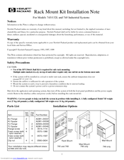
Rack Mount Kit Installation Note for Models 745/132L and 748 Industrial Systems
Brand:
HP
| Category:
Racks & Stands
| Size: 0.06 MB
HP Model 745 - VME Workstation Declaration Of Conformity (1 page)
PCI Module - 4 Slot Declaration of Conformity
Brand:
HP
| Category:
Accessories
| Size: 0.01 MB
Table of Contents
Manufacturer Information
1
Product Information
1
Specifications
1
Supplementary Information
1
HP Model 745 - VME Workstation Declaration Of Conformity (1 page)
ATM Adapter Declaration of Conformity
Brand:
HP
| Category:
Adapter
| Size: 0.01 MB
HP Model 745 - VME Workstation Declaration Of Conformity (1 page)
PMC Bridge Declaration of Conformity
Brand:
HP
| Category:
Accessories
| Size: 0.01 MB
Advertisement
Related Products
HP Model 748 - VME Workstation
HP Model 743 PC
HP Model 743 - Workstation
HP Model 715/64 - Workstation
HP Model 715/80 - Workstation
HP Model 715/50 - Workstation
HP Model 712/60 - Workstation
HP Model 712/80 - Workstation
HP Model 712/100 - Workstation
HP Model 715/33 - Workstation
HP Categories
Desktop
Laptop
Server
Monitor
Switch
More HP Manuals
Login
Sign In
OR
Sign in with Facebook
Sign in with Google
Upload manual
Upload from disk
Upload from URL