Sign In
Upload
Manuals
Brands
Frick Manuals
Control Panel
QUANTUM
Frick QUANTUM Manuals
Manuals and User Guides for Frick QUANTUM. We have
6
Frick QUANTUM manuals available for free PDF download: Maintenance Manual, Operation Manual, Operation
Frick QUANTUM Maintenance Manual (116 pages)
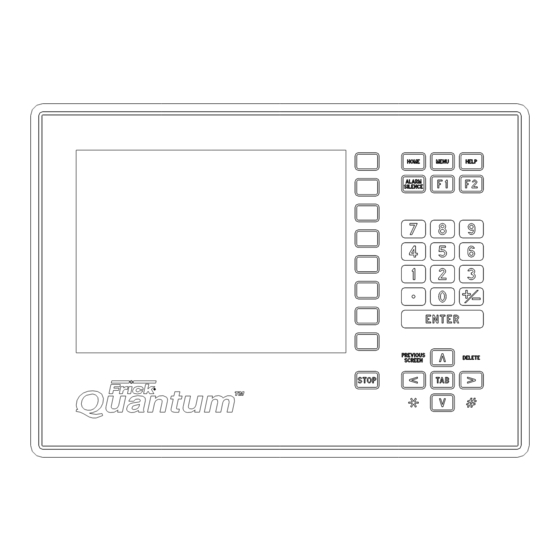
HD COMPRESSOR CONTROL PANEL
Brand:
Frick
| Category:
Control Panel
| Size: 8 MB
Table of Contents
Table of Contents
2
Section 1 - Control System
5
Control Panel Enclosure
6
General Information
6
Introduction
6
What to Do before Calling the Factory
7
Section 2 - Quantum ™ Hd Operator Interface
9
Description
10
Display Assembly
10
Figure 1. LCD Display Assembly & Mounting
10
Table 1. Q5 Processor Board Display Jumpers
10
Table 2. Keyboard Mapping
11
Touchscreen Description
11
Using an External Usb Style Keyboard or Mouse
11
Section 3 - Q5 Processor Board & Interface
13
Features
14
Figure 2. Q5 Processor Board Photo
14
Introduction
14
What if the Operating Status Screen Is Not Shown
14
What Should Occur When Applying Power
14
Battery Function and Replacement
15
Figure 3. Interface Board Photo
15
Interface Board Description
15
Figure 4. Q5 Processor Board Diagram
16
Q5 Processor Board Jumpers, Led's and Connectors
17
Table 3. Q5 Board Jumper Settings
17
Table 4. Q5 Board LED Definitions
17
Table 5. Q5 Board Connector Pinouts
17
Figure 5. Interface Board Diagram
18
Figure 6. Pinouts and Jumper Locations
18
Table 6. JP1 System Settings
18
Table 7. Comms 1 & 2 Jumper Settings
18
Figure 7. Q5 Processor Board Interconnections
19
Figure 8. Q5 Processor Board Mounting
20
Section 4 - Power Supply
21
Description
22
Figure 9. Power Supplies
22
Measuring Voltages
22
Power Distribution
22
Figure 10. Power Supply Adjustment
23
Section 5 - Digital Board
25
Power Supply Replacement
23
Communications Led's
26
Connections to the Quantum™ Hd
26
Digital Board Description
26
Figure 11. Return Lead
26
Information
26
Logic Voltage (Power) Led
26
Active Led
27
Checking the Digital Inputs and Outputs
27
Digital Inputs
27
Digital Outputs
27
Figure 12. Digital Input Modules - Side View
27
Figure 13. Digital Output Module - Side View
27
Figure 14. Signal Connections
27
Fuse Testing and Replacement
28
Input and Output Module Testing and Replacement
28
Replacing a Defective Digital Board
28
Troubleshooting an Input
28
Troubleshooting an Output
28
Figure 15. Digital I/O Board #1
29
Figure 16. Digital I/O Board #2
30
Digital Board Settings
31
Table 8. Communication Settings
31
Table 9. Dipswitch Settings
31
Section 6 - 614 Analog Board
33
Analog Board Description
34
Communications Led's
34
Connections to the Quantum™ Hd
34
Figure 17. Return Lead
34
Logic Voltage (Power) Led's
34
Overview
34
Active Led
35
Analog Inputs
35
Table 10. Analog Board Input Configuration Table
35
Analog Outputs
36
Figure 18. Signal Connections
36
Replacing a Defective Analog Board
36
Table 11. Resistor Values
36
Troubleshooting the Analog Inputs and Outputs
36
Figure 19. PHD Connections (Analog Board #1)
37
Phd Vibration Analysis
37
Current Transformer (Motor Amps)
38
Figure 20. Current Transformer
38
Figure 21. Analog Board #1
39
Figure 22. Analog Board #2
40
Analog Board Settings
41
Table 12. Communications
41
Table 13. Dipswitch Settings (Used to Set Board Address)
41
Table 14. Analog Board Jumper Settings
41
Section 7 - Service Screens
43
Service - Oil Pump
44
Service - Maintenance (Factory)
45
Service - Maintenance (User Defined)
46
Service - Communications
47
Service - Diagnostics
48
Figure 23. USB Plug-In Locations
49
Service - Software
49
Status - Filter Info
52
Status - Vyper Info
52
Status - Panel (Analog)
53
Status - Panel (Digital)
53
Status - Panel (Comms 1-3)
54
Status - Panel (Io Comms)
54
Status - Panel (Comm 1-3 Log)
55
Status - Panel (Io Comms Log)
55
Status - Dbs Starter Info
56
Status - Panel (Modbus Tcp Log)
56
About
57
Configuration - Drive (Motor)
57
Section 8 - Troubleshooting
59
Troubleshooting Chart for Frick Quantum Hd Control Panel
60
Quantum ™ Hd Drawings
65
Table 15. Quantum HD Drawings List
65
Figure 24. Quantum HD Panel Assembly
66
Figure 25. RXF Wiring Diagram (Capacity Slide Transmitter)
70
Figure 26. RWFII Wiring Diagram (Capacity Slide Transmitter)
76
Figure 27. RXF/RXB Wiring Diagram (Cap. Slide Potentiometer)
82
Figure 28. RWBII Wiring Diagram (Cap. Slide Potentiometer) (1/6
88
Figure 29. RDB Wiring Diagram
94
Figure 30. Phd Wiring Diagram
100
Figure 31. Digital I/O Board #2 Wiring Diagram
101
Figure 32. Analog I/O Board #2 Wiring Diagram
103
Figure 33. HD AC Power Harness
105
Figure 33A. HD AC Power Harness (Digital Board #2)
106
Figure 34. Isolater Repeater Module
107
Figure 35. Communications Wiring Diagrams
108
Figure 36. Point-To-Point Field Wiring Diagram
109
Table 16. Pressure Transducer Conversation Data
111
Tables
111
Table 17. Compressor Volume Ratio & Capacity Information
112
Control Panel Replacement Parts List
113
Section 11 - Replacement Parts List
113
Table 18. HD Compressor Control Replacements Parts List
113
Remanufactured Parts
114
Table 19. Remanufactured Parts
114
Advertisement
Frick QUANTUM Operation Manual (112 pages)
Compressor Control Panel
Brand:
Frick
| Category:
Control Panel
| Size: 2 MB
Table of Contents
Table of Contents
2
Overview of Operator Interface
4
Common Terminology
4
Operator Access
4
Keys and Key Functions
5
Keypad Keys
5
To Change Setpoints
6
Screen Description - Operating Status
7
Compressor Data Box
7
Compressor Alarm Status Box
7
Setpoint Box
8
Status Box of Oil Lubrication Devices
8
Motor Indication Box
8
Communications Box
8
Capacity Control Box
8
Sensor Indication Box
9
Slide Valve and Slide Stop (or Capacity) Status Box
9
Screen Key Descriptions
11
Operating Status
11
Compressor
12
Operating Status - 2
13
Main Menu
14
Main Menu - Screen Key Set
14
Alarms/Shutdowns
15
Alarms/Shutdowns History
16
Operating Status -- Freeze
16
Control Setup
17
Capacity Control Setpoints
18
Suction Pressure Control
18
Process Temperature Control
20
User Selectable Control Setup
21
Compressor Safeties Setpoints
22
Discharge Safeties
22
Suction Safeties
23
Entering Process Safeties
24
Motor Control
25
Varispeed
26
Electric - VFD
27
Engine
28
RAM DBS Motor Starter
29
RAM DBS Motor Starter - Fault History
31
Oil Setpoints
32
Liquid Injection Cooling Setpoints
34
Main Oil Injection Setpoints
34
Filter Pressure Setpoints
35
Slide Valve Setpoints
36
Economizer Setup
37
Setback Schedule
38
Control Setup
39
Options Setup
40
Auxiliary Setup
41
Auxiliary Analog (Temperatures & Pressures)
42
Pumpdown/DX Circuit
43
PID Setup
44
Setting up a PID Channel
45
Overview to Tuning a PID Controller
46
Digital Output #18 Control
47
Condenser Control
47
Compressor Sequence Control (MODE 1)
50
Compressor Sequence Overview (Mode 1)
52
Compressor Sequence Control (MODE 2)
54
Compressor Sequence Overview (Mode 2)
56
Compressor Interlock
58
Input Module Selection
59
Auxiliary Setup
60
Pull down
61
Vibration Monitoring
62
Security Setup
63
Calibration and Setup
64
Analog Calibration
65
Pressure Calibration
66
Calibrate Motor Current
67
Temperature Calibration
67
Calibrate Slide Stop
68
Calibrate Slide Valve
69
Calibrate Slide Valve Position
70
Remote Control Calibration
70
Calibrate Auxiliary Analog
71
Calibrate Level Position
71
Calibrate Auxiliary Analog (Pressure)
72
Analog Output Setup
73
Analog Output Setup
74
Kilowatt Monitor Calibration
75
Change Current Time and Date
76
Panel Setup
76
Pressure Units -- PSIA, PSIG, or si
77
Temperature Units -- Degrees Fahrenheit or Celsius
77
Change Communications
78
Language
78
Capacity Control Options
79
Selectable Options
80
Selectable Options (Page 2)
81
Selectable Options
82
Selectable Options
83
Screen Settings
84
Real Time Trending
85
Real Time Trending Screen (Data Log View)
86
History Trending
87
Service Screen (Analog Board)
88
Service Screen (Digital Board)
88
Scheduled Maintenance
89
Alpha Select
90
Compressor Start-Up Procedure
91
Compressor Stopping Procedure
91
Initial Setup Procedure
91
Operation Overview
91
Remote Control of the Compressor
91
Setup for Automatic Control
91
Alarms/Shutdowns Messages
93
Oil Safety Logic
99
Part 1: Missing Oil Pressure
99
Part 2: Insufficient Main Oil Pressure During Low Differential
99
Part 3: Oil Circuit Pressure Drop
100
Part 4: Oil Pressure Filter Drop
101
Index
107
Frick QUANTUM Maintenance Manual (82 pages)
COMPRESSOR CONTROL PANEL
Brand:
Frick
| Category:
Control Panel
| Size: 4 MB
Table of Contents
Table of Contents
2
Quantum Identification
5
Quantum 3
5
Quantum 4
5
Troubleshooting
5
The Quantum Control Panel
5
General Information
5
What to Do before Calling the Factory
6
What Should Occur When Powering up the Panel
6
What if the "Operating Status" Screen Is Not Shown
6
Display Assembly Component Replacement Guide
8
Quantum 3
8
Quantum 4
8
Troubleshooting Analog and Digital Problems
9
About" Screen
9
Diagnosing an Analog or Digital Board Problem
9
Service Screen" - Digital Board Inputs and Outputs
10
Troubleshooting Digital Inputs and Outputs
10
Troubleshooting Analog Inputs and Outputs
11
Adding and Replacing Boards
12
Quantum
12
Analog and Digital Boards
12
Display Replacement
13
Troubleshooting a Problem that Appears Unexplainable
14
Compressor Model Differences
18
Jumper and Dipswitch Settings
19
Digital Board
19
Digital I/O Board Communications Settings
19
Digital I/O Board Dipswitch Settings
19
Analog Board
19
Analog Board Communications Settings
19
Analog Board Dipswitch Settings
19
Analog Board #1
20
Analog Board #2
21
Quantum 3
22
Communications Settings Com-1
22
Communications Settings Com-2
22
Communications Settings Com-3
22
Quantum 4
23
Communications Settings Com-1
23
Communications Settings Com-2
23
Setpoint Data Sheets
24
Factory Setup
24
Panel Setup
26
Calibration
28
Capacity Control Setpoints
29
Suction Pressure Control Mode #1
29
Suction Pressure Control Mode #2
30
Process Temp Control Mode #1
30
Process Temp Control Mode #2
31
Discharge Pressure Control Mode #1
31
Discharge Pressure Control Mode #2
32
Discharge Temp Control Mode #1
32
Discharge Temp Control Mode #2
33
Compressor Safeties
33
Discharge Safeties
33
Suction Safeties
34
Entering Process Temperature
34
High Level Shutdown Delay
34
Motor Control
34
Power Failure Restart
34
Ram Dbs Motor Starter
35
Oil Setpoints
35
Main Oil Injection
35
Liquid Injection
35
Filter Pressure Setpoints
35
Slide Valve Setpoints
36
Options
36
Setback Schedule
36
Condenser Control Setpoints
36
Analog Control
36
Compressor Sequence Setpoints
37
Auxiliary Inputs Setup
37
Suction Pull-Down
37
Auxiliary Analogs
38
Pumpdown/DX Circuits
38
Wiring Diagrams
39
Flow Diagram D.C. Voltage Harness
39
Point-To-Point Field Wiring Diagram
39
Quantum Panel DC Power Supply Diagram (Condor)
40
Quantum Panel D.C. Power Supply Diagram (Power-One)
40
Quantum 3 Main Processor Board
41
Quantum 4 Main Processor Board
42
Digital I/O Board #1
43
Digital I/O Board #2
44
Analog Board #1
45
Analog Board #2
46
Quantum 3 Control Center Assembly
47
Quantum 3 Control Center Assembly Rxf 12-50 Only
49
Quantum 4 Control Center Assembly
51
Quantum 4 Control Center Assembly Rxf 12-50 Only
53
Wiring Diagram - Rwf
55
Wiring Diagram - Rwb II
59
Wiring Diagram - Rxf (12-50)
63
Wiring Diagram - Rxf (58-101) - Rxb
67
Wiring Diagram - Rdb
71
Wiring Diagram Quantum Digital I/O Board 2
75
Wiring Diagram Quantum Analog I/O Board 2
77
Quantum 3 Communications Wiring Diagrams
79
Quantum 4 Communications Wiring Diagrams
80
Pressure Transducer Conversion Data
81
Recommended Spare Parts
82
Advertisement
Frick QUANTUM Operation (84 pages)
CONTROL PANEL
Brand:
Frick
| Category:
Control Panel
| Size: 5 MB
Table of Contents
Table of Contents
2
Operation
4
Quick Overview of Graphic Displays
4
Overview of Operator Interface
5
Operator Access
5
Keys and Key Functions
6
Keypad Keys
6
Screen Keys
7
To Change Setpoints
7
Common Terminology
8
Operating Status" Screen
8
Operating Status" Screen - Screen Key Set
11
Operating Status - 2" Screen
12
Main Menu" Screen
13
Main Menu" Display - Screen Key Set
13
Main Menu Selection - "Alarms/Shutdowns" Screen
14
Main Menu Selection - "Alarms/Shutdowns History" Screen
15
Main Menu Selection - "Control Setup" Screen
15
Control Setup - Capacity Control Setpoints Screens
16
Process Temperature Control" Screen
19
Control Setup - Compressor Safeties Setpoints
19
Control Setup - Compressor Safeties - "Discharge Safeties" Screen
20
Control Setup - Compressor Safeties - "Suction Safeties" Screen
21
Control Setup - Compressor Safeties - "Entering Process Safeties" Screen
22
Control Setup - "Motor Control Setpoints" Screen
23
CONTROL SETUP - MOTOR CONTROL SETPOINTS - "Electric - VFD" SCREEN
24
Control Setup - Motor Control Setpoints - "Ram Dbs Motor Starter
25
CONTROL SETUP - MOTOR CONTROL SETPOINTS - "Turbine" SCREEN
26
Control Setup - Motor Control Setpoints - "Ram Dbs Motor Starter" Screen
28
Control Setup - "Oil Setpoints" Screen
29
Control Setup - "Slide Valve Setpoints" Screen
32
Control Setup - "Setback Schedule" Screen
33
CONTROL SETUP - "Options Setup" SCREEN
34
CONTROL SETUP - OPTIONS SETUP - "Condenser Control" SCREEN
34
CONTROL SETUP - OPTIONS SETUP - "Compressor Sequence Control" (MODE 1) SCREEN
36
Compressor Sequence Overview
39
CONTROL SETUP - OPTIONS SETUP - "Compressor Sequence Control" (MODE 2) SCREEN
40
Compressor Sequence Overview
43
CONTROL SETUP - OPTIONS SETUP "Compressor Interlock" SCREEN
45
CONTROL SETUP - OPTIONS SETUP - "Input Module Selection" SCREEN
46
CONTROL SETUP - OPTIONS SETUP - "Auxiliary Setup" SCREEN
47
Control Setup - "Suction Pressure Pull Down" Screen
48
Control Setup - "Auxiliaries 3 - 8 Setup" Screen
49
Control Setup - "Auxiliary Analog Temperatures & Pressures" Screen
50
Control Setup - "Pumpdown/DX Circuit Setup" Screen
51
MAIN MENU SELECTION - "Security Setup" SCREEN
52
MAIN MENU SELECTION - "Analog Calibration" SCREEN
53
ANALOG CALIBRATION - "Pressure Calibration" SCREEN
54
ANALOG CALIBRATION - "Temperature Calibration" SCREEN
55
ANALOG CALIBRATION - "Calibrate Motor Current" SCREEN
56
ANALOG CALIBRATION - "Calibrate Slide Stop" SCREEN
56
ANALOG CALIBRATION - "Calibrate Slide Valve" SCREEN
57
Analog Calibration - "Calibrate Remote Control Setpoint" Screen
58
ANALOG CALIBRATION - "Calibrate Slide Valve Position" SCREEN
59
ANALOG CALIBRATION - "Calibrate Level Position" SCREEN
59
ANALOG CALIBRATION - "Calibrate Auxiliary Analog" SCREEN
60
CONTROL SETUP - "Analog Output Setup" SCREEN
61
ANALOG CALIBRATION - "Kilowatt Monitor Calibration" SCREEN
62
MAIN MENU SELECTION - "Panel Setup" SCREEN
62
PANEL SETUP - "Change Current Time and Date" SCREEN
63
PANEL SETUP - "Pressure Units - PSIA, PSIG, or SI" SCREEN
63
PANEL SETUP - "Temperature Units - Degrees Fahrenheit or Celsius" SCREEN
63
PANEL SETUP - "Capacity Control Options" SCREEN
63
PANEL SETUP - "Language - English, Danish, German" SCREEN
63
PANEL SETUP - "Change Communications" SCREEN
63
PANEL SETUP - "Selectable Options" DISPLAY
64
PANEL SETUP - SELECTABLE OPTIONS - "Screen Settings" SCREEN
67
Main Menu" Selection - "Real Time Trending" Screen
68
Real Time Trending" Screen - Data Log View
69
Real Time Trending" Screen - Trending View
69
Real Time Trending - Operating Status View
70
Main Menu Selection - "History Trending" Screen
70
MAIN MENU" SCREEN - "Service Screen" SCREEN
71
Operation Overview
72
Initial Setup Procedure
72
Compressor Start-Up Procedure
72
Compressor Stopping Procedure
72
Setup for Automatic Control
72
Remote Control of the Compressor
72
Alarms/Shutdowns Messages
74
Flowcharts
74
QUANTUM AUTOMATIC CAPACITY CONTROL (Electric, VFD, Engine, Turbine) Version 3.5X
78
OIL PUMP STARTING LOGIC (Frick Prelube, Cycling, Demand)
80
OIL PUMP STARTING LOGIC (Frick no Pump )
81
OIL PUMP STARTING LOGIC (Frick Full Lube)
82
Frick QUANTUM Maintenance Manual (72 pages)
Brand:
Frick
| Category:
Control Panel
| Size: 4 MB
Table of Contents
Table of Contents
2
Troubleshooting
3
Adding and Replacing Boards
13
Display Replacement
13
Compressor Model Differences
14
Jumper and Dipswitch Settings
15
Digital Board
15
Digital I/O Board Communications Settings
15
Digital I/O Board Dipswitch Settings
15
Analog Board
15
Analog Board Communications Settings
15
Analog Board Dipswitch Settings
15
Analog Board #1
15
Analog Board #2
17
Main Board
18
Main Board Communications Settings Com-1
18
Main Board Communications Settings Com-2
18
Main Board D-Ram Settings
18
Setpoint Data Sheets
19
Factory Setup
19
Panel Setup
20
Calibration
22
Capacity Control Setpoints
24
Suction Pressure Control Mode #1
24
Suction Pressure Control Mode #2
24
Process Temp Control Mode #1
25
Process Temp Control Mode #2
25
Discharge Pressure Control Mode #1
26
Discharge Pressure Control Mode #2
26
Discharge Temp Control Mode #1
27
Discharge Temp Control Mode #2
27
Compressor Safeties
28
Discharge Safeties
28
Suction Safeties
28
Entering Process Temperature
28
High Level Shutdown Delay
28
Motor Control
29
Power Failure Restart
29
Ram DBS Motor Starter
29
Oil Setpoints
29
Main Oil Injection
30
Liquid Injection
30
Filter Pressure Setpoints
30
Slide Valve Setpoints
30
Options
30
Setback Schedule
30
Condenser Control Setpoints
30
Compressor Sequence Setpoints
31
Auxiliary Inputs Setup
31
Suction Pull-Down
31
Auxiliary Analogs
32
Pumpdown/DX Circuits
32
Flow Diagram D.C. Voltage Harness
33
Point-To-Point Field Wiring Diagram
33
Power Supply Diagram (Condor)
34
Power Supply Diagram (Power-One)
34
Main Processor Board
35
Digital I/O Board #1
36
Digital I/O Board #2
37
Analog Board #1
38
Analog Board #2
39
Control Center Assembly
40
Control Center Assembly RXF 12 - 50 Only
42
Wiring Diagrams Rwb II
48
Rxf (12-50)
52
Rxf (58-101) - Rxb
56
Rdb
60
Digital I/O Board 2
64
Digital I/O Board - RXF 12 - 50 Only
66
Analog I/O Board 2
68
Quantum Multicompressor Sequencing RS-485 Communications
70
Quantum/Rwb II/RDB/RXB/RXF Multicompressor Sequencing - RS-422 Communications
70
Pressure Transducer Conversion Data
71
Recommended Spare Parts
72
Frick QUANTUM Operation Manual (34 pages)
EVAPORATOR CONTROL PANEL
Brand:
Frick
| Category:
Control Panel
| Size: 0 MB
Table of Contents
Table of Contents
2
Quick Overview of Graphic Screens
3
Overview of Operator Interface
4
Operator Access
4
Keys and Key Functions
5
Keypad Keys
5
Screen Keys
6
To Change Setpoints
6
Initial Setup Procedure
7
Zone Overview" Screen
7
Graphic Screens
7
Zone Overview" Screen - Screen Key Set
8
Zone Overview - 2" Screen
9
Zone Selected - "Operating Status" Screen
10
Evaporator Data Box
10
Alarm Status Box
10
Evaporator I/O Status Box
11
Defrost & Heating Status Box
11
Analog Readings Box
11
Operating Status" Screen - Screen Key Set
12
Zone Selected - "Main Menu" Screen
13
Main Menu" Screen - Screen Key Set
13
Main Menu Selection - "Alarms/Shutdowns" Screen
14
Main Menu Selection - "Control Setup" Screen
15
Control Setup - "Temperature Setpoint" Screens
16
Control Setup - Temperature Setpoints - "Mode 1 Setpoints" Screen
16
Control Setup - "Time Schedule" Screen
19
Control Setup - "Defrost Schedule" Screen
20
Control Setup - "Defrost Setpoints" Screen
21
Control Setup - "Heating Setpoints" Screen
23
Control Setup - "Safety Setpoints" Screen
24
Main Menu Selection - "Analog Calibration" Screen
26
Analog Calibration - "Temperature Calibration" Screen
27
Analog Calibration - "Humidity Calibration" Screen
28
Analog Calibration - "Ammonia Calibration" Screen
28
Analog Calibration - "Calibrate Motor Current" Screen
29
Main Menu Selection - "Service Screen" Screen
30
Panel Setup" Screen
31
Panel Setup - "Change Current Time and Date" Screen
31
Panel Setup - "Temperature Units -- Degrees Fahrenheit or Celsius" Screen
31
Panel Setup - "Language - English, Spanish " Screen
31
Panel Setup - "Change Communications" Screen
31
Panel Setup - "Group Setup" Screen
32
Panel Setup - "Screen Settings" Screen
32
Security Setup" Screen
33
Alarms/Shutdowns Messages
34
Advertisement
Related Products
Frick QUANTUM LX Control Panel
Frick QUANTUM LX AcuAir
Frick QUANTUM HD
Frick QUANTUM Series
Frick Quantum ACUair
Frick QUANTUM LX EVAPORATOR
Frick QUANTUM HD UNITY
Frick RXF Plus
Frick Categories
Control Panel
Air Compressor
Industrial Equipment
Compressor
Air Conditioner
More Frick Manuals
Login
Sign In
OR
Sign in with Facebook
Sign in with Google
Upload manual
Upload from disk
Upload from URL