Sign In
Upload
Manuals
Brands
Delta Electronics Manuals
DC Drives
ASD-A2023-AB
Delta Electronics ASD-A2023-AB Manuals
Manuals and User Guides for Delta Electronics ASD-A2023-AB. We have
2
Delta Electronics ASD-A2023-AB manuals available for free PDF download: User Manual
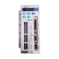
Delta Electronics ASD-A2023-AB User Manual (358 pages)
ASDA-AB Series Advanced AC Servo Drive for General Purpose Applocations
Brand:
Delta Electronics
| Category:
DC Drives
| Size: 9.65 MB
Table of Contents
Installation
3
Unpacking Check
3
Main Circuit Wiring
4
Maintenance and Inspection
4
Operation
4
Wiring
4
Table of Contents
6
User Information
12
Chapter 1 Unpacking Check and Model Explanation
14
Delta Standard Supplied Parts
14
Optional Parts
14
Unpacking Check
14
Model Explanation
15
Nameplate Information
15
ASDA-AB Series Servo Drive
15
ASMT Series Servo Motor
15
Model Name Explanation
16
ECMA Series Servo Motor
17
Servo Drive and Servo Motor Combinations
18
Servo Drive Features
19
Control Modes of Servo Drive
21
Chapter 2 Installation and Storage
22
Installation Conditions
23
Operating Temperature
23
Installation Procedure and Minimum Clearances
24
Drive Mounting
24
Minimum Clearances
24
Motor Mounting
24
Side by Side Installation
25
Connecting to Peripheral Devices
26
V Servo Drive
26
Installation and Storage
22
Installation Notes
22
Storage Conditions
22
Chapter 3 Connections and Wiring
26
110V Servo Drive
27
Servo Drive Connectors and Terminals
28
Wiring Notes
29
Single-Phase Power Supply
30
Wiring Methods
30
Motor Power Cable Connector Specifications
32
Encoder Connector Specifications
33
Cable Specifications for Servo Drive
34
Encoder Cable
35
Basic Wiring
36
Basic Wiring Schematic of 100W
36
Basic Wiring Schematic of 2Kw, 220V Models
37
Basic Wiring Schematic of 100W ~ 400W, 110V Models
38
Input / Output Interface Connector -CN1
39
CN1 Terminal Identification
39
The Layout of CN1 Drive Connector
39
CN1 Terminal Signal Identification
40
Signals Explanation of Connector CN1
41
General Signals
41
DO Signals
42
DI Signals
44
Source of Position Command
47
Source of Speed Command
47
Source of Torque Command
47
Default DI Signals and Control Modes
48
Default DO Signals and Control Modes
50
User-Defined DI and DO Signals
51
Wiring Diagrams of I/O Signals (CN1)
51
Speed / Torque Analog Signal Input
51
C2: Analog Monitor Output (MON1, MON2)
51
C4: Pulse Input (Line Driver)
52
CN2 Terminal Signal Identification
56
Encoder Connector CN2
56
The Layout of CN2 Drive Connector
56
Serial Communication Connector CN3
57
CN3 Terminal Layout and Identification
57
CN3 Terminal Signal Identification
57
Connection between PC and Connector CN3
58
Standard Connection Example
59
Position (Pt) Control Mode (220V Models)
59
Position (Pt) Control Mode (110V Models)
60
Position (Pr) Control Mode (220V Models)
61
Position (Pr) Control Mode (110V Models)
62
Speed Control Mode (220V Models)
63
Speed Control Mode (110V Models)
64
Torque Control Mode (220V Models)
65
Torque Control Mode (110V Models)
66
Description of the Digital Keypad
68
Chapter 4 Display and Operation
68
Display Flowchart
69
Keypad Operation
69
Status Display
70
Save Setting Display
70
Abort Setting Display
70
Fault Message Display
70
Monitor Setting Display
71
General Function Operation
73
Fault Code Display Operation
73
JOG Operation
74
Position Learning Operation
75
DO Force Output Diagnosis Operation
76
DI Diagnosis Operation
77
DO Diagnosis Operation
77
Inspection Without Load
78
Chapter 5 Trial Run and Tuning Procedure
78
Applying Power to the Drive
80
Turn the Power on
80
Over Voltage
81
Encoder Error
81
Emergency Stop Activated
81
Reverse Limit Switch Error
82
Forward Limit Switch Error
82
Overcurrent
83
Undervoltage
83
JOG Trial Run Without Load
84
Speed Trial Run Without Load
86
Position Trial Run Without Load
88
Tuning Procedure
91
Tuning Flowchart
92
Load Inertia Estimation Flowchart
93
Automode (PI) Tuning Flowchart
94
Automode (PDFF) Tuning Flowchart
96
Auto Mode Responsiveness Level
96
Manual Mode Tuning Flowchart
98
Speed Mode
99
Limit of Load Inertia Estimation
99
Relationship between Tuning Modes and Parameters
100
Gain Adjustment in Manual Mode
100
KPP, Parameter P2-00 Proportional Position Loop Gain
101
KVP, Parameter P2-04 Proportional Speed Loop Gain
101
KVI, Parameter P2-06 Speed Integral Compensation
101
DST, Parameter P2-26 External Anti-Interference Gain
102
PFG, Parameter P2-02 Position Feed Forward Gain
102
Control Modes of Operation
104
Chapter 6 Control Modes of Operation
104
Position Control Mode
105
Command Source of Position (Pt) Control Mode
105
External Pulse Input Type
105
Command Source of Position (Pr) Control Mode
106
Structure of Position Control Mode
107
P-Curve Filter for Position Control
108
Pulse Inhibit Input Function (INHP)
108
P-Curve Characteristics and Time Relationship (Acceleration)
109
P-Curve Characteristics and Time Relationship (Deceleration)
109
Deceleration Time
110
Accel /Decel S-Curve
110
Electronic Gear Ratio
111
Electronic Gear Ratio (1St Numerator) (N1)
111
Electronic Gear Ratio (Denominator)
111
Low-Pass Filter
112
Smooth Constant of Position Command
112
Timing Chart of Position (Pr) Control Mode
113
Position Loop Gain Adjustment
113
Proportional Position Loop Gain
114
Position Feed Forward Gain
114
Speed Control Mode
116
Command Source of Speed Control Mode
116
Structure of Speed Control Mode
117
Smoothing Strategy of Speed Control Mode
118
S-Curve Filter
118
Analog Speed Input Scaling
121
Max. Analog Speed Command / Limit
121
Timing Chart of Speed Control Mode
122
Speed Loop Gain Adjustment
122
Tuning Mode Selection
123
Manual Mode
123
Proportional Speed Loop Gain
124
Speed Integral Compensation
124
Speed Feed Forward Gain
124
Frequency Domain
125
Time Domain
126
Auto Mode (Continuous Adjustment))
127
Resonance Suppression
127
Notch Filter (Resonance Suppression)
127
Notch Filter Attenuation Rate
128
Low-Pass Filter Time Constant
128
Torque Control Mode
131
Command Source of Torque Control Mode
131
Structure of Torque Control Mode
132
Smoothing Strategy of Torque Control Mode
132
Smooth Constant of Analog Torque Command
132
Analog Torque Input Scaling
133
Max. Analog Torque Command / Limit
133
Timing Chart of Torque Control Mode
134
Control Modes Selection
135
Speed / Position Control Mode Selection
135
Pt-S Mode / Pr-S Mode
135
Speed / Torque Control Mode Selection
136
Torque / Position Control Mode Selection
136
Others
138
Speed Limit
138
Torque Limit
138
Command Source Selection of Speed Limit
138
Regenerative Resistor
139
Built-In Regenerative Resistor
139
Built-In Regenerative Resistor Specifications
139
External Regenerative Resistor
140
Regenerative Power Calculation Method
140
Simple Calculation Method
142
Analog Monitor
143
Analog Monitor Output
143
Pulse Output Polarity Setting
144
Analog Monitor Output Proportion 1 (CH1)
144
Analog Monitor Output Proportion 2 (CH2)
144
Analog Monitor Output Drift Adjustment (CH1)
144
Analog Monitor Output Drift Adjustment (CH2)
145
Electromagnetic Brake
146
BRKR Output Timing Explanation
146
Electromagnetic Brake Wiring Diagram
147
Servo Parameters
150
Definition
150
Abbreviation of Control Modes
150
Explanation of Symbols (Marked after Parameter)
150
Chapter 7 Parameters
150
Monitor Parameters
151
Parameters List by Group
151
Parameters Summary
151
Basic Parameters
152
Extension Parameters
154
Diagnosis Parameters
157
Monitor and General Use
158
Parameters List by Function
158
Smooth Filter and Resonance Suppression
159
Gain and Switch
160
Position Control
161
Digital I/O
165
Communication
166
Detailed Parameter Listings
169
Drive Fault Code
169
Firmware Version
169
Drive Status
170
Status Monitor 1
171
Block Data Read / Write Register 0
173
Block Data Read / Write Register 1
173
Servo Output Status Display
175
Control Mode and Output Direction
177
Speed and Torque Limit
178
1St Torque Command or Limit
181
3Rd Speed Command or Limit
181
1St Position Command for Rotation
182
2Nd Torque Command or Limit
182
1St Position Command for Pulse
183
2Nd Position Command for Pulse
183
2Nd Position Command for Rotation
183
3Rd Position Command for Pulse
184
4Th Position Command for Pulse
184
4Th Position Command for Rotation
184
5Th Position Command for Rotation
184
5Th Position Command for Pulse
185
6Th Position Command for Pulse
185
6Th Position Command for Rotation
185
7Th Position Command for Rotation
185
7Th Position Command for Pulse
186
8Th Position Command for Pulse
186
8Th Position Command for Rotation
186
Motor Type Selection
186
Motor Stop Mode Selection
187
Position Control Mode (Pr)
187
Acceleration Time
188
Target Motor Speed
190
Zero Speed Range Setting
190
Max. Analog Speed Command or Limit
191
Max. Analog Torque Command or Limit
191
On Delay Time of Electromagnetic Brake
191
OFF Delay Time of Electromagnetic Brake
192
Encoder Output Pulse Number
194
Homing Mode
195
1St Speed Setting of High Speed Homing
196
2Nd Speed Setting of Low Speed Homing
196
Homing Offset Pulse Number
196
Homing Offset Rotation Number
196
Maximum Speed Limit
197
Positioning Completed Width
197
Regenerative Resistor Capacity
197
Regenerative Resistor Value
197
Output Overload Warning Level
198
Position Loop Gain Switching Rate
200
Smooth Constant of Position Feed Forward Gain
201
Speed Loop Gain Switching Rate
201
Digital Input Terminal 1 (DI1)
204
Digital Input Terminal 2 (DI2)
204
Digital Input Terminal 3 (DI3)
204
Digital Input Terminal 4 (DI4)
205
Digital Input Terminal 5 (DI5)
205
Digital Input Terminal 6 (DI6)
205
Digital Input Terminal 7 (DI7)
205
Digital Output Terminal 1 (DO1)
206
Digital Output Terminal 2 (DO2)
206
Digital Output Terminal 3 (DO3)
206
External Anti-Interference Gain
208
Gain Switching Control Selection
208
Auxiliary Function
209
Gain Switching Condition
209
Gain Switching Time Constant
209
Easy Setting of Input Filter
212
Excessive Error Warning Condition
212
Overspeed Warning Condition
212
Moving Speed Setting of 1St Position
213
Moving Speed Setting of 2Nd Position
213
Moving Speed Setting of 3Rd Position
213
Moving Speed Setting of 4Th Position
213
Moving Speed Setting of 5Th Position
214
Moving Speed Setting of 6Th Position
214
Combination Output Signal Delay Time
215
Digital Output Mode Setting
215
Feed Step Number
215
Backlash Compensation of Feed Step Control
216
Position Deviation Clear Delay Time
216
Enable/Disable Jitter Suppression Function
217
Speed Detection Filter and Jitter Suppression
217
Speed Detection Filter Constant
217
Pulse Deviation Clear Mode
218
Servo on
219
Timer 0 of Auto Mode
219
Timer 1 of Auto Mode
219
Timer 2 of Auto Mode
219
Electronic Gear Ratio (3Rd Numerator) (N3)
221
Electronic Gear Ratio (4Th Numerator) (N4)
221
Proportion Value Setting
222
Torque Limit Mixed Mode
223
Bit2: Fast DI Contact Type
224
Bit3 ~ Bit4: Fast DI Function Definition
224
Special Function
224
Bit10: DI ZCLAMP Function Selection
225
Bit6: Abnormal Pulse Command Detection
225
Communication Address Setting
226
Transmission Speed
226
Communication Protocol
227
Transmission Fault Treatment
227
Communication Selection
228
Communication Time out Detection
228
Communication Response Delay Time
229
Digital Input Communication Function
229
Fault Record (N)
230
Fault Record (N-1)
230
Digital Keypad Input of Servo Drive
232
Force Output Control
232
Input Status or Force Input Control
232
Adjustment Function
233
Analog Speed Input Drift Adjustment 1
233
Output Status Display
233
Analog Speed Input Drift Adjustment 2
234
Analog Torque Drift Adjustment 1
234
Current Detector Drift Adjustment (V1 Phase)
234
Current Detector Drift Adjustment (V2 Phase)
235
Current Detector Drift Adjustment (W1 Phase)
235
Current Detector Drift Adjustment (W2 Phase)
235
IGBT NTC Calibration
235
Input Function Definition
238
Cable Connection
244
Communication Hardware Interface
244
Chapter 8 MODBUS Communications
244
Communication Parameter Settings
248
MODBUS Communication Protocol
252
Code Description
252
ASCII Mode
252
Data Format
252
11-Bit Character Frame (for 8-Bit Character)
253
RTU Mode
253
CRC (RTU Mode)
257
Communication Parameter Write-In and Read-Out
260
Basic Inspection
262
Chapter 9 Maintenance and Inspection
262
Life of Replacement Components
263
Smooth Capacitor
263
Relay
263
Maintenance
263
Cooling Fan
264
Fault Messages Table
266
Servo Drive Fault Messages
266
Chapter 10 Troubleshooting
266
Potential Cause and Corrective Actions
268
Overvoltage
268
Regeneration Error
269
Overload
269
Overspeed
269
Abnormal Pulse Control Command
269
Watch Dog Execution Time out
270
Adjustment Error
270
Reverse (CWL) Limit Switch Error
270
IGBT Temperature Error
271
Memory Error
271
DSP Communication Error
271
Serial Communication Error
271
Command Write-In Error
272
Input Power Phase Loss
272
Pre-Overload Warning
272
Internal Command Execution Time out
272
Clearing Faults
273
Chapter 11 Specifications
276
Specifications of Servo Drive (ASDA-AB Series)
276
Low Inertia Servo Motor
279
Specifications of Servo Motor (ECMA Series)
279
Medium / High Inertia Servo Motor
280
Servo Motor Speed-Torque Curves
282
Overload Characteristics
283
Overload Protection Function
283
Occasion of Overload
283
Chart of Load and Operating Time
283
Dimensions of Servo Drive
291
Dimensions of Servo Motor
295
Parameters Setting
298
Chapter 12 Application Examples
298
Position Control (Including Homing Function)
298
Roller Feeding
300
Connecting to Delta DVP-EH Series PLC
301
Connecting to Delta TP04 Series
306
Position Control Mode (Pr Mode)
308
Trigger Timing Charts
309
Timing Chart of Internal Position Register Selection
309
HOLD Timing Chart
309
Command Abort Timing Chart
310
Feed Step Control
311
Relevant Parameters Description
311
Digital I/O Signal Setting
312
Mode Functions
313
Timing Charts of DI/DO Signals Operation
316
Feed Step Control Mode
317
Manually Single Step Control Mode 1
318
Manually Single Step Control Mode 2
319
Manually Continuous Step Control Mode
320
Communication Control Example Explanation
321
Internal Auto Running Mode
322
Definitions of DO Signals (ON:1, OFF:0)
324
Homing Function
327
A: Home Sensor Type and Homing Direction
327
Homing Moving Method
328
Homing Enable Setting
328
Homing Stop Setting
329
Recommended Homing Modes
329
Homing Timing Charts
329
Timing Charts of Enable Homing Mode
329
External Controller Connection Examples
334
Connecting to Delta DVP-EH PLC
334
Connecting to Delta DVP-01PU
335
Connecting to Mitsubishi FX1PG
336
Connecting to Mitsubishi FX2N1PG
337
Connecting to Mitsubishi AD75
338
Power Connectors
340
Appendix A Accessories
340
Power Cables
341
Communication Cable between Drive and Computer (for PC)
347
I/O Signal Connector (CN1)
347
Terminal Block Module
347
Servo Drive, Servo Motor and Accessories Combinations
348
400W Servo Drive and 300W High Inertia Servo Motor
349
400W Servo Drive and 500W Medium Inertia Servo Motor
349
750W Servo Drive and 750W Low Inertia Servo Motor
349
1Kw Servo Drive and 1Kw Low Inertia Servo Motor
350
1Kw Servo Drive and 1Kw Medium Inertia Servo Motor
350
750W Servo Drive and 600W High Inertia Servo Motor
350
1.5Kw Servo Drive and 1.5Kw Medium Inertia Servo Motor
351
1Kw Servo Drive and 900W High Inertia Servo Motor
351
2Kw Servo Drive and 2Kw Medium Inertia Servo Motor
352
Other Accessories
352
Appendix B Molded-Case Circuit Breaker, Fuse Current and EMI Filters
354
Circuit Breaker and Fuse Current Values
354
Dimensions
357
Advertisement
Delta Electronics ASD-A2023-AB User Manual (343 pages)
Advanced AC Servo Drive for General Purpose Applications
Brand:
Delta Electronics
| Category:
Servo Drives
| Size: 14.13 MB
Table of Contents
Table of Contents
6
Chapter 1 Unpacking Check and Model Explanation
14
Unpacking Check
14
Model Explanation
15
Nameplate Information
15
Model Name Explanation
16
Servo Drive and Servo Motor Combinations
18
Servo Drive Features
19
Control Modes of Servo Drive
21
Chapter 2 Installation and Storage
22
Installation Notes
22
Storage Conditions
22
Installation Conditions
23
Installation Procedure and Minimum Clearances
24
Molded-Case Circuit Breaker and Fuse Current Recommended Value
26
EMI Filter Selection
26
Regenerative Resistor
30
Chapter 3 Connections and Wiring
36
Connections
36
Connecting to Peripheral Devices
36
Servo Drive Connectors and Terminals
38
Wiring Methods
40
Motor Power Cable Connector Specifications
42
Encoder Connector Specifications
43
Cable Specifications for Servo Drive
47
Basic Wiring
49
CN1 Terminal Identification
52
Signals Explanation of Connector CN1
54
Wiring Diagrams of I/O Signals - CN1
64
Encoder Connector CN2
69
Serial Communication Connector CN3
71
Connection between PC and Connector CN3
72
Standard Connection Example
73
Position (Pt) Control Mode (220V Models)
73
Position (Pt) Control Mode (110V Models)
74
Position (Pr) Control Mode (220V Models)
75
Position (Pr) Control Mode (110V Models)
76
Speed Control Mode (220V Models)
77
Speed Control Mode (110V Models)
78
Torque Control Mode (220V Models)
79
Torque Control Mode (110V Models)
80
Chapter 4 Display and Operation
82
Description of Digital Keypad
82
Display Flowchart
83
Status Display
84
Save Setting Display
84
Abort Setting Display
84
Fault Message Display
84
Polarity Setting Display
84
Monitor Setting Display
85
General Function Operation
87
Fault Code Display Operation
87
JOG Operation
88
Position Learning Operation
89
DO Force Output Diagnosis Operation
90
DI Diagnosis Operation
91
DO Diagnosis Operation
91
Chapter 5 Trial Run and Tuning Procedure
92
Inspection Without Load
92
Applying Power to the Drive
94
JOG Trial Run Without Load
98
Speed Trial Run Without Load
100
Position Trial Run Without Load
102
Tuning Procedure
105
Tuning Flowchart
106
Load Inertia Estimation Flowchart
107
Automode (PI) Tuning Flowchart
108
Automode (PDFF) Tuning Flowchart
110
Manual Mode Tuning Flowchart
112
Limit of Load Inertia Estimation
113
Relationship between Tuning Modes and Parameters
114
Gain Adjustment in Manual Mode
114
Chapter 6 Control Modes of Operation
118
Control Modes of Operation
118
Position Control Mode
119
Command Source of Position (Pt) Control Mode
119
Command Source of Position (Pr) Control Mode
120
Structure of Position Control Mode
121
P-Curve Filter for Position Control
122
Electronic Gear Ratio
125
Low-Pass Filter
126
Timing Chart of Position (Pr) Control Mode
127
Position Loop Gain Adjustment
127
Speed Control Mode
130
Command Source of Speed Control Mode
130
Structure of Speed Control Mode
131
Smoothing Strategy of Speed Control Mode
132
Analog Speed Input Scaling
135
Timing Chart of Speed Control Mode
136
Speed Loop Gain Adjustment
136
Resonance Suppression
141
Torque Control Mode
145
Command Source of Torque Control Mode
145
Structure of Torque Control Mode
146
Smoothing Strategy of Torque Control Mode
146
Analog Torque Input Scaling
147
Timing Chart of Torque Control Mode
148
Control Mode Selection
149
Speed / Position Control Mode Selection
149
Speed / Torque Control Mode Selection
150
Torque / Position Control Mode Selection
150
Others
152
Speed Limit
152
Torque Limit
152
Analog Monitor
153
Electromagnetic Brake
156
Chapter 7 Servo Parameters
160
Definition
160
List of Parameters
161
Parameter Description
168
Specifications of Servo Motor (ECMA Series)
271
Servo Motor Speed-Torque Curves
275
Overload Characteristics
276
Dimensions of Servo Drive
278
Dimensions of Servo Motor
282
Chapter 11 Application Examples
286
Position Control (Including Homing Function)
286
Roller Feeding
288
Connecting to Delta DVP-EH Series PLC
289
Connecting to Delta TP04 Series
294
Position Control Mode (Pr Mode)
296
Feed Step Control
299
Homing Function
315
External Controller Connection Examples
322
Appendix A Accessories
328
Appendix B Maintenance and Inspection
342
Advertisement
Related Products
Delta Electronics ASD-A2023LA
Delta Electronics ASD-A2023MA
Delta Electronics ASD-A0111-AB
Delta Electronics ASDA-A Series
Delta Electronics ASD-A0221LA
Delta Electronics ASD-A0721LA
Delta Electronics ASD-A3023LA
Delta Electronics ASD-A3023MA
Delta Electronics ASD-A1521MA
Delta Electronics ASD-A1021LA
Delta Electronics Categories
Power Inductor
Power Supply
Computer Hardware
Fan
Transceiver
More Delta Electronics Manuals
Login
Sign In
OR
Sign in with Facebook
Sign in with Google
Upload manual
Upload from disk
Upload from URL