Sign In
Upload
Manuals
Brands
Arbiter Systems Manuals
Measuring Instruments
1133A
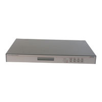
Arbiter Systems 1133A Power Measurement Manuals
Manuals and User Guides for Arbiter Systems 1133A Power Measurement. We have
2
Arbiter Systems 1133A Power Measurement manuals available for free PDF download: Operation Manual, Quick Setup Manual
Arbiter Systems 1133A Operation Manual (192 pages)
GPS-SYNCHRONIZED POWER QUALITY REVENUE STANDARD
Brand:
Arbiter Systems
| Category:
Recording Equipment
| Size: 4 MB
Table of Contents
Table of Contents
6
1 Unpacking the 1133A
21
Introduction
21
Precautions
21
Unpacking and Locating Accessories
22
Attaching Rack-Mount Ears to 1133A
22
Packaging of Accessories
22
Attaching Rack-Mount Ears
23
2 Front and Rear Panels
24
Introduction
24
Front Panel Controls and Indicators
24
Model 1133A Front Panel Description
24
Annunciator LED Definitions
25
Fault Indications and Definitions
25
Command Key Definitions
26
Rear Panel Connectors and Identification
26
Model 1133A Rear Panel Description
26
Antenna Connector
27
Antenna or IRIG-B Input
27
High Voltage Power Inlet
27
Low Voltage Power Inlet
27
Power Inlet
27
AC Current Inputs
28
AC Voltage Inputs
28
Current Input Connector
28
Event Input Connector
28
Event Inputs
28
Voltage Input Connector
28
Communication Ports
29
Communication Ports Connectors
29
Form C Contacts
29
IRIG-B Connector
29
IRIG-B Timing Output
29
Relay Contact Connector
29
3 Connecting Inlet Power, Input and Output Signals
30
Introduction
30
Connecting Inlet Power
30
Option 03, 110 to 350 VDC Terminal Power Strip, Surge Withstand
30
Option 03 Power Supply Inlet Connector
30
Option 04, 10 VDC to 60 VDC ONLY, Terminal Power Strip Surge Withstand
31
Fuse Locations and Types
31
Option 04 Power Supply Inlet Connector
31
Fuse Chart
31
Connecting Voltage and Current Signals
32
AC Voltage Inputs
32
AC Current Inputs
32
Electrical System Connection Diagrams
32
Connection Diagram - DSP Notation, 1Ph2W1E
33
Connection Diagram - DSP Notation, 1Ph2W1.5E
34
Connection Diagram - DSP Notation, 1Ph3W2E
35
Connection Diagram - DSP Notation, 3Ph3W2E
36
Connection Diagram - DSP Notation, 3Ph4W2.5E
37
Connection Diagram - DSP Notation, 3Ph4W3E
38
Relay Contact Outputs
39
Event Inputs
39
IRIG-B Output
39
Relay Contact Connector
39
Event Input Connector
39
Data Connections
40
Serial Interface Connections
40
Ethernet Interface Connections
40
IRIG-B Connector
40
Serial Cable Connector Pin Locations
40
Serial Interface Connector Description
40
4 GNSS Antenna and Cable Information
41
GNSS Antenna Installation
41
Mounting the Antenna
41
Optional Antenna Mounting Bracket
42
Antenna Assembly for Mounting
42
Antenna Mounting Bracket Parts List
42
Antenna Mounting Bracket
43
Antenna Mounting with AS0044600
43
Verifying Antenna and Cable Operation
44
Checking the Antenna Voltage
44
Power Supply Check
44
Checking the Antenna Resistance
44
GNSS Surge Arrester
44
Using the Antenna Surge Arrester
44
Technical Details on GNSS, Antennas and Cables
45
Antenna Cable
45
GNSS Cable Data and Accessory Information
46
5 Startup Operation and Indication
48
Startup
48
Startup Display Indications
48
Locked Indication
48
Initial Startup Screen
48
Copyright Startup Screen
48
GNSS Status Screen
48
Annunciator LED Startup Indications
49
Viewing Electrical Parameters
49
Overview of Command Keys
49
Voltage/Current Key
49
GNSS Locked Screen
49
Voltage/Current Display
49
Frequency/Time Deviation Key
50
Event Log Key
50
Status/Time Keys - Primary Functions
50
Freq./Time Dev. Display
50
Event Log Display
50
Status, Locked Display: GNSS or IRIG-B
50
Status, Location: Latitude and Longitude
51
Status, Date and Time
51
Status, 1133A Configuration
51
Status, 1133A Flash Memory
51
Status/Time Keys - Secondary Functions
52
Status, Program Information
52
Status, Calibration Information
52
Status, Ethernet; Address and Subnet Mask - Default Shown
52
Power Key
53
Energy Key
53
Status, Ethernet; TCP/UDP Port and Physical Address
53
Status, Serial Port Parameters
53
Harmonics Key
54
Flicker Key
54
Unlocked and System Fault Indication
54
Unlocked Indication
54
Fault Indication
54
Fault Indications
55
6 PSCSV Basics - Starting, Connecting and Logging in
56
Introduction
56
Getting Started
56
Triggering from the DSP, Power Quality, and from I/O Connections
56
C37.118 Phasor Broadcast
56
Power Quality, DNP and Modbus
57
Scheduled Data, Relays and KYZ Pulses
57
Menus, Toolbars, Buttons and Windows
57
Moving and Viewing Features
57
PSCSV Main Window
57
Toolbar and Button Definitions
58
Main Toolbar
58
Connection Toolbar
58
Broadcast Toolbar
58
Configuration Toolbar
59
Flash Toolbar
59
Input Toolbar
60
Flash Toolbar
60
Records Toolbar
61
View Menu
61
Edit Menu
61
Connecting with the 1133A
62
Introduction
62
Communication Ports
62
Rear Panel Description
62
Starting PSCSV
63
Checking Communication Parameters on the 1133A
63
Opening a Connection
63
Types and Uses of 1133A Serial Connections
63
Connection List Shows Ethernet Selected
64
Connection List Shows RS-232 Selected
64
Adding a TCP or UDP Connection
65
Renaming a TCP or UDP Connection
66
Removing a TCP or UDP Connection
66
Closing a Connection
66
Automatic Connection Closure
66
Special Note on 115200 Baud Rates
66
Logging in to the 1133A
66
Security Features, Login Window
66
Logging in Using Admin
67
Security, User Permissions Window
67
7 Configuring the Model 1133A
68
Introduction
68
1133A Configuration Options by Section
68
Basic Configuration Requirements
68
Configuring an 1133A Communication Port
68
To View COM Port Settings on the 1133A
69
Configure Ports - Communication Ports 1 and 2
69
Configuring COM1 Settings
69
Configure Ports - Ethernet
70
Configuring Ethernet Settings
70
Additional Information on Ethernet Connections
71
Check the Computer Network Settings with Ipconfig
71
Ping the 1133A Port
71
Configuring Measurement Parameters
71
Measurement Parameters Configuration Screen
72
CT Cal. Points
72
Configure Ports - IRIG-B
73
Configure IRIG-B Settings
73
Configure Ports - DNP 3.0 Protocol
74
Configuring Class 0 Data
74
Selecting DNP in COM Port 1 Setting
74
Configuring DNP Settings
75
DNP 3.0 Class 0 Definition Selection
75
Configure Ports - Modbus
76
Selecting MODBUS in COM 1 Settings
76
Configure Ports - C37.118 Synchrophasor Protocol
77
Setup
77
PMU Setup Terms and Definitions
77
Configuration
78
Window Functions
79
Setup Example - Ethernet
80
8-Cycle, Raised Cosine Rejection Plot and 6-Cycle Rolloff
80
Selecting Digital Channels in C37.118
80
Audible Frequency Alert, from Phasor Display
81
Broadcasting UDP Data
82
Transmitting UDP, Arbiter Protocol
82
Frequency Alert and Setup Window
82
Broadcasting UDP, C37.118 Synchrophasor Data
83
Shows PMU-1 Set to Broadcast UDP
83
UDP Configuration Frame Mode and Interval
83
Configuring Multimode Relays
84
Configuring User Schedule Mode
84
Configure Relay Parameters
84
Configuring Pulse-Per-Hour Mode
85
Configuring KYZ Pulse Metering
85
Configure Pulse-Per-Hour Mode
85
Configure KYZ Mode
85
Kp Register Scale Factors
86
Configure KYZ Scale Factors
86
Configuring Relays for Trigger Mode
87
Configuring and Using Communication Mode
87
Configuring Position and Time
87
Configure Relays for Trigger Mode
87
Configure Relays for Manual Override Mode
87
Configuring Scheduled Data
88
Configure Position and Time
88
Configuring Time Deviation
89
Configuring Scheduled Data Screen
89
Configuring Time Deviation Screen
89
1133A Security - Setting up User Accounts and Permissions
90
Introduction
90
Security Features
90
An Overview of 1133A Security
90
Security Specifications
91
Using Power Sentinel Security
91
Changing the Admin Password
91
Security Definitions
91
Permanent Login Information
91
Setting up New User Accounts
92
Deleting User Accounts
92
Security, User Permissions Window
92
How to Disable 1133A Security so that Everything Is Available
93
Flash Memory Management
93
Introduction
93
Flash Memory Functions
93
Flash Memory Security
94
Configuring Flash Memory
94
Checking Flash Memory Status
94
Configure Flash Window
94
Erasing Flash Memory
95
Downloading Scheduled Data
95
Flash Status Window
95
Erasing Scheduled Data
96
Downloading Event Data
96
Erasing Event Data
96
Uploading a Configuration
96
Create/Edit Uploadable Configuration
96
Erase Flash Window
96
Configure Choices
97
Uploading the New Configuration
97
Create/Edit Configuration File Menu
97
Upload Configuration Window
98
8 Working with Triggers and Downloading Event Records
99
Introduction to Triggers and Events
99
Configuring User (DSP) Triggers
99
User Trigger Parameter Definitions
100
User Trigger Setup Procedure
100
DSP Trigger Setup Screen
100
Configuring Power Quality Triggers
101
Power Quality Parameter Definitions
101
Power Quality Trigger Setup Procedure
102
Power Quality Trigger Setup Screen
102
Hysteresis Plot
103
Triggering from External Events
104
Configure External Event Inputs Screen
104
Logging Data When Triggers Occur
105
System Triggers
105
Configure Data Logged Screen
106
Configure Logging Parameters Screen
106
Data Logged" Procedure Details
106
Configuring Schulz-Laios Settings
107
Configure Data Items Screen
107
Configuring Event Notification
108
Downloading Triggered Events from Flash
108
Configuring Event Notification Screen
108
Concluded Event Record Download
109
List of Event Records
110
9 Working with Broadcast Data
111
Introduction
111
Filter Data Selection Tool
111
Basic Data Selection Screen
111
Broadcast Data Choices
112
Logging Basic Data
112
Broadcast Data Choices and Descriptions
112
Logging Energy Data
113
Basic Data Summary Screen
113
Basic Data Spreadsheet Screen
113
Energy Data Summary Screen
114
Energy Data Spreadsheet Screen
114
Logging Harmonic Data
115
Harmonic Data Summary Screen
115
Harmonic Data Spreadsheet Screen
115
Logging Harmonic Summary Data
116
Harmonic Data Spreadsheet Screen
116
Harmonic Data Summary Screen
116
Harmonic Summary Values
117
Harmonic Load Currents
118
Harmonic Summary Data
118
Logging Waveform Data
118
Waveform Data Screen
118
Logging Phasor Data
119
Logging Phase Data
120
Phasor Data Screen
120
Phasor-Frequency Plot Data Screen
120
Exporting Data in CSV Format
121
Phase Summary Data Screen
121
Phase Spreadsheet Data Screen
121
Exporting Data in PQDIF Format
122
Export CSV Format Data Screen
122
10 Working with Scheduled Data
123
Introduction
123
Topics Addressed in this Section
123
Protocols
123
Registered or Scheduled Data
123
Downloading Scheduled Data with PSCSV
124
Logging Data with KYZ Pulse Metering
124
Logging Scheduled Data Using Other Protocols
124
DNP 3.0 and Modbus Protocols
124
Checking the Flash Memory Status
124
Downloading Scheduled Data Using PSCSV
125
Flash Status Screen
125
Scheduled Data Download Specify Range
126
Scheduled Data Download Session
126
Configuring Scheduled Storage
127
Scheduled Data Summary View
127
Erasing Scheduled Data Using PSCSV
128
1133A Scheduled Data Values
128
Energy Values
128
Voltage Values
128
Sequence Values
129
Frequency Variation Values
129
Flicker
129
Harmonics
129
How Energy Is Totalized in the Model 1133A
129
Example, Totalizing Energy
130
11 Functional Description
131
Overview
131
GNSS Synchronization
131
Current Inputs
131
Voltage Inputs
132
Self Calibration
132
Error Analysis
132
Signal Sampling
132
Power and Energy
132
Power & Energy Error Analysis
133
Voltage and Current
134
CT and PT Compensation
134
Transformer Compensation
134
DC Offsets
135
Phase and Frequency
135
Harmonics
136
Flicker
137
Interruptions
137
Voltage Fluctuations
137
System Time Deviation
137
Phasor Measurements
137
Phase Balance
138
Load Balance
138
Flash Memory and Event Logging
138
Contact Outputs
139
Event Inputs
139
Serial Channels
139
Ethernet MMS Interface
140
Triggering in the Model 1133A
140
Detecting Oscillatory Transients and Other Anomalies
141
Signal Functions Available for Triggering
142
Trigger Channel Parameter Summary
143
Schulz-Laios Transient Detector Values
143
Trigger Channel Parameter Summary (32 Channels)
143
Schulz-Laios
143
12 Technical Specifications and Operational Parameters
144
Scope
144
Standard Options
145
1133A Standard Options
145
AC Voltage and Current Inputs
146
Input Configurations
146
Input Voltage
146
Input Current
146
Volt-Amps (VA), Watts (W), Volt-Amp-Reactance (VAR)
146
Compensating Constants and Ratios
146
Input Frequency Range
146
Input Connector Ratings
147
Instrument Interface
147
Front Panel Indicators and Controls
147
External Interface Connections
147
Programmable Contact Output Connections
147
Event Input Connections
148
Flash Memory Data Storage
149
DSP Configuration
149
IP Address
150
Ethernet (Physical) Address
150
Measurement Specifications
150
Power Quality Measurement Capability
151
Harmonic Measurements
151
Power Interruptions
151
Flicker
151
Limit Alarms
152
System Control and Monitoring
152
System Time, Phase and Frequency
152
Phasors
152
Synchronization
153
GNSS Information
153
GNSS Antenna & Cable Characteristics
153
Synchronization Output - IRIG-B
153
Time Base Error
154
Instrument Power Requirements
154
General Specifications
154
Physical Specifications
154
Environmental Specifications
154
Temperature and Humidity List
154
13 DNP 3.0 and MODBUS Data Structures
155
Introduction
155
Definitions and Conventions
155
Dnp 3.0
155
Modbus
155
32-Bit Numbers & Little Endian
156
Scale Factors
156
Voltage and Current Data Structure
157
Voltage and Current Register Values
157
Power Data Structure
158
Power Register Values
158
Frequency, Flicker and Relative Phase Data Structure
159
Frequency, Flicker and Relative Phase Register Values
159
Harmonic and Harmonic Summary Data Structure
161
Harmonic and Harmonic Summary Register Values
161
Individual Harmonic Voltages and Currents
162
Energy Register Values
163
Energy Values
163
Trigger Status
164
Trigger Status Values
164
14 Event Input Voltage Settings
165
General Information
165
Event Input Specifications
165
Standard Event Input Voltage, 24 - 240 VDC
165
Optional Event Input Voltage, 5 VDC, Logic Level
165
15 Accurate CT Calibration for the Model 1133A
167
Overview
167
Calibration Process
167
Calibrated Reference CT
167
Excitation Current Source
168
Comparison Technique
168
Accessories
169
Selection of the Current Calibration Points
170
Conclusion
170
A Working with Ethernet Connections
171
Checking the Computer Network Settings
171
Setting an IP Address on the Computer
172
Setting an IP Address on the 1133A
172
B Using Surge Arresters
173
Introduction
173
Description
173
Installation
174
Mounting Location
174
Ground Connection
174
Antenna and Clock Connections
174
Weather Sealing the Connections
174
Suggested Mounting
174
Physical Dimensions
175
C IRIG-B Primer
176
Introduction
176
Modulated and Unmodulated IRIG-B
176
IRIG-B Type Codes
177
IRIG-B C37.118 Extension
177
Connecting the IRIG-B Output
178
Screw Terminals
178
How Far Can I Run IRIG-B Cabling
178
Synchronizing Multiple Ied's from One Masterclock Output
178
Connecting Unmodulated IRIG-B
179
Wire Losses
179
Cable Delays
179
Solutions
180
D CE Mark Certification
181
Introduction
181
E Vorne Output Values
183
Introduction
183
Vorne Protocol in Use
183
Description of Vorne Protocol
183
Advertisement
Arbiter Systems 1133A Quick Setup Manual (4 pages)
Brand:
Arbiter Systems
| Category:
Measuring Instruments
| Size: 0 MB
Table of Contents
Unpacking
1
Attach Rack-Mount Ears
1
Installing GNSS Antenna
1
Inlet Power Connection
2
System Ground
2
Confirming Basic Operation
2
Communication Cable Connections
3
Setting up PSCSV Software
3
Starting PSCSV
3
Security
3
Configuring the Connected System
4
Downloading Data
4
Additional Help
4
Advertisement
Related Products
Arbiter Systems 1092A
Arbiter Systems 1092B
Arbiter Systems 1092C
Arbiter Systems 1093A
Arbiter Systems 1093C
Arbiter Systems 1093B
Arbiter Systems 1073A
Arbiter Systems 1084A
Arbiter Systems 1084C
Arbiter Systems 1088B
Arbiter Systems Categories
Clock
Measuring Instruments
Amplifier
Antenna
Multimeter
More Arbiter Systems Manuals
Login
Sign In
OR
Sign in with Facebook
Sign in with Google
Upload manual
Upload from disk
Upload from URL