Sign In
Upload
Manuals
Brands
Arbiter Systems Manuals
Clock
1084A
Arbiter Systems 1084A Manuals
Manuals and User Guides for Arbiter Systems 1084A. We have
2
Arbiter Systems 1084A manuals available for free PDF download: Operation Manuals, Manual
Arbiter Systems 1084A Operation Manuals (256 pages)
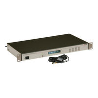
SATELLITE-CONTROLLED CLOCK
Brand:
Arbiter Systems
| Category:
Clock
| Size: 4.44 MB
Table of Contents
Table of Contents
7
1 Unpacking the Clock
21
Introduction
21
Precautions
21
Unpacking and Locating Accessories
21
Attaching Rack-Mount Ears to 1084A/B/C Series Clocks
22
Mounting Instructions
22
Packaging of Accessories
22
Attaching Rack-Mount Ears
23
2 Front and Rear Panels
25
Introduction
25
Front Panel Controls and Indicators
25
Annunciator LED Definitions
26
Command Key Definitions
26
Model 1084A/B/C Front Panel Description
26
LED Status Indicators
27
LCD Display
27
Front Panel Keys
27
Rear Panel Identification and Connectors
28
Power Inlet
28
Model 1084A/B/C Rear Panel Description
28
Antenna Input
29
Event Input
29
Option 07 Power Supply Inlet Connector
29
Option 08 Power Supply Inlet Connector
29
Option 10 Power Supply Inlet Connector
29
GPS Antenna Connector
29
Antenna and Cable Information
29
And RS-485 Communication Ports
30
Form C, Relay Contacts
30
Standard Input/Outputs
30
Communications Port Connector
30
Relay Contact Connectors
30
Standard Input/Output Connectors
30
3 Connecting Inlet Power, Input and Output Signals
31
Physical Configuration
31
Option 07, IEC-320 Power Inlet Module
32
Cordsets and Plug Styles for Option 07
32
Option 07, Connecting Power to the 1084A/B/C
32
Option 07 Power Supply Inlet Description
32
Option 08, 10 to 60 VDC Power with Terminal Power Strip and Surge Withstand
33
Option 08, Connecting Inlet Power
33
Option 10, 110 to 350 VDC Terminal Power Strip, Surge Withstand
33
Option 10, Connecting Inlet Power
33
Option 08 Power Supply Inlet Description
33
Option 10 Power Supply Inlet Description
33
Fuse Types and Locations
34
Replacing Fuses
34
Connecting Output Signals
34
Connecting Input Signals
34
Fuse Chart
34
Connecting an Event Input at P3 or Main RS-232 Port
35
4 GPS Antenna and Cable Information
37
GPS Antenna Installation
37
Mounting the Antenna
37
Optional Antenna Mounting Kit
38
Antenna Assembly for Mounting
38
Antenna Mounting Bracket Parts List
38
Antenna Mounting Bracket
39
Antenna Mounting with AS0044600
39
Verifying Antenna and Cable Operation
40
Checking the Antenna Voltage
40
Power Supply Check
40
Checking the Antenna Resistance
40
GPS Surge Arrester
40
Using the GPS Surge Arrester
40
Technical Details on GPS, Antennas and Cables
41
Antenna Cable
41
5 Setting Internal Jumpers
45
Introduction
45
Input/Output, Function Selection
45
Output Function at P1, no Jumper
46
JMP1, I/O Connector Used as Input
46
Model 1084A/B/C Main Board
46
JMP2, Fiber Optic Output (Option 20)
47
JMP3, Digital Output at P3
47
JMP4, Relay Control Output
47
JMP5, Receiver Battery (Option 02) Obsolete
47
JMP6, Output Enable
48
JMP7, Model 1089A/B/C Timing Input Selection Obsolete
48
JMP9, P2 Output Selection
48
JMP10, RS-232 DSR or Prog. Pulse Output Selection
48
JMP11, Model 1089A/B/C Obsolete
48
6 The Setup Menus
49
Setup Menus
50
To Begin Configuring
50
Numeric Data Entry Mode
51
Default Firmware Settings
51
To Exit Setup Menus
51
Setting the Main RS-232C Port
52
Main RS-232C Setup
52
Setting Port Parameters
53
Setting the Broadcast Mode from Main RS-232
53
Port Parameter Setup
53
Broadcast Setup
53
Set Local Hour
54
Examples
54
Local Hour Setup
54
Set Daylight Saving Time (DST)
55
Auto Daylight Saving Setup
55
Set out of Lock
56
Out-Of-Lock Setup
56
Set Back Light
57
Back Light Setup
57
Set System Delays
58
Cable Delay
58
Clock Offset
58
System Delay Setup
58
Set Programmable Pulse Mode
59
Entering Numerical Values
59
Programmable Pulse Setup
59
Prog Pulse, Seconds-Per-Pulse Mode
60
Seconds-Per-Pulse Setup
60
Prog Pulse, Pulse-Per-Hour Mode
61
Pulse-Per-Hour Setup
61
Prog Pulse, Pulse-Per-Day Mode
62
Pulse-Per-Day Setup
62
Prog Pulse, Single Trigger
63
Single Trigger Setup
63
Prog Pulse, Slow Code
64
Slow Code Setup
64
Prog Pulse - Pulse Polarity
65
Pulse Polarity Setup
65
Set IRIG Time Data
66
IRIG-B Time Data Setup
66
Set the Event or Deviation Modes
67
Arming the Event Input
67
Event/Deviation Mode Setup
67
Arming the Event Mode from Front Panel
67
Set the Auto Survey Mode
68
Number of Fixes
68
Survey Mode Setup
68
Set Position Hold on or off
69
Edit Position Data
69
Position Hold Mode Setup
69
Set Option Control
70
Option Control Setup
70
7 Timing, IRIG-B and Pulses
71
Introduction
71
Timing Output Description
71
Standard Inputs/Outputs
72
Digital Drivers
72
Analog Driver
72
Rear Panel Descriptions
72
Drive Current Vs. Voltage
72
Output Signal Description
73
IRIG-B Description
73
Modulated and Unmodulated IRIG-B
73
IRIG-B Time Code Types Available
73
IRIG-B IEEE 1344 Extension
74
Pulse-Per-Second (1 PPS)
74
IRIG-B Waveforms
74
Connecting Outputs
75
Programmable Pulse (PROG PULSE)
75
Attaching Cables to Screw Terminals
75
How Far Can I Run IRIG-B Cabling
75
Programmable Pulse Types
75
Synchronizing Multiple Ied's from One Masterclock Output
76
Connecting Unmodulated IRIG-B
76
Connecting Modulated IRIG-B
76
Wire Losses
77
Voltage Matching for Modulated IRIG-B
77
Cable Delays
78
Solutions
78
Relay Contacts and Event Inputs
79
Relay Contacts, out of Lock and Fault
79
Introduction
79
Out-Of-Lock Relay Operation
79
Fault Relay Operation
79
Failsafe Operation
79
Relay Contact Connectors
79
Event Inputs
80
Event Timing Input
80
Event Timing Latency
80
Deviation Measurement
80
Measurement Principle
80
Event Timer Input Channel Configuration
81
Firmware Setup
81
Displaying Data
81
RS-232C Event Trapping
82
Event Trapping Setup
82
9 Serial Communication and Command Set
83
Introduction
83
Command Set
83
Broadcast Mode Commands
85
Event Mode Commands
89
Status Mode Commands
91
Local / Daylight Savings Time Setup Commands
95
Front Panel Control Commands
96
IRIG-B Data Output Commands
97
Position Data Commands
98
Survey Mode Commands
100
Date and Time Commands
101
Programmable Pulse Output Commands
102
Antenna System Delay Commands
104
Out-Of-Lock Commands
104
Miscellaneous Commands
104
Option Control Settings
105
Communication Port Information
106
Main RS-232C Port Pin Definitions
106
10 Startup and Basic Operation
107
Initial Startup Sequence
107
Clock Time, Startup Mode - 1084B/C
107
Front Panel Indication - 1084B/C
108
Display Indication at Startup
108
Other Display Indications When Unlocked
108
Status Display Indications
109
Event/Deviation Display
109
IRIG-B Time Data
110
Clock Status Display Mode
110
Time Display Modes - 1084B/C
110
Date and Time Display, Universal Time Coordinated (UTC)
111
Time of Year Display, UTC
111
Date and Time Display, Local Time
111
Time of Year Display, Local Time
111
Daylight Saving-Summer Time
112
Position Display Modes - 1084B/C
112
Longitude Display
112
Latitude Display
112
Elevation Display
113
A Technical Specifications and Operating Parameters
115
Scope
115
Receiver Characteristics
115
Input Signal
115
Timing Accuracy
115
Internal Oscillator, Stability
115
Allen Variance
115
Position Accuracy (Rms)
116
Satellite Tracking
116
Acquisition
116
I/O Configuration
116
I/O Connectors
116
Standard Output Signals
116
Relay Contacts
117
Programmable Pulse Output
117
Event a Input - Alternate Function
117
Antenna System
117
Antenna Cable
117
Operator Interface
117
Setup Methods
117
Setup Functions
118
Display
118
Display Functions
118
Annunciators
118
Setup Functions Listed
118
System Interface
119
RS-232C Interface
119
Data Formats
119
Physical Specifications
119
Dimensions
119
Weight
120
Power Requirements
120
Power Connector
120
Electro-Magnetic Interference (EMI)
120
Temperature and Humidity
120
Temperature and Humidity List
120
B Using Surge Arresters
121
Introduction
121
Description
121
Installation
121
Mounting Location
121
Ground Connection
121
Antenna and Clock Connections
122
Weather Sealing the Connections
122
Suggested Mounting
122
Physical Dimensions
122
Suggested Mounting of the AS0094500 Surge Arrester
123
C Options List
125
Introduction
125
Option 01: Backlighted LCD Display
126
General Description - 1084B/C Only
126
Specifications
126
Configuration
126
Option 02: GPS Battery Backup - Obsolete
127
General Description
127
Specifications
127
Option 03: Four Additional Outputs - Obsolete
128
General Description
128
Specifications
128
Digital Outputs
128
C.4 Option 03: Four Additional Outputs – Obsolete
129
Option 03 Jumper Configuration
130
Output Connector Jumper Settings
131
Option 04: ON/OFF Switch
132
Model 1084A/B/C Clocks
132
Option 06: Parallel BCD Output (1 Millisecond Resolution)
133
General Description
133
Option 06 Firmware Setup
134
Specifications
135
C.6.3 Specifications
135
Digital Outputs
136
Option 06, Connector Pin Designation
137
Option 06 Output Connector
138
Configuration
139
C.6.6 Configuration
139
Option 06 Output Jumper Settings
142
Option 06 Board Layout and Jumper Locations
143
Option 07: Inlet Power Supply Description
144
85 To 264 Vac, 47 to 440 Hz, 110 to 370 VDC, IEC-320 Connector
144
Specifications
144
Option 07 Power Supply Inlet Connector
144
Option 08: Inlet Power Supply Description
145
10 To 60 VDC ONLY, Terminal Power Strip, SWC
145
Specifications
145
Option 08 Power Supply Inlet Connector
145
Option 10: Inlet Power Supply Description
146
110 To 350 VDC, 85 to 250 Vac, 47 to 440 Hz Terminal Power Strip, SWC
146
Specifications
146
Option 10 Power Supply Inlet Connector
146
Option 17: Parallel BCD Output and Second RS-232C Port
147
General Description
147
Option 17 Firmware Setup Procedure
148
Option 17 Firmware Setup
148
Specifications
149
C.10.3 Specifications
149
Digital Outputs
150
Option 17, Connector Pin Designation
152
Option 17 Output Connector
153
Configuration
154
C.10.6 Configuration
154
Option 17 Output Jumper Settings
157
Option 17 Board Layout and Jumper Locations
158
Option 19: Second RS-232C Interface
159
General Description
159
Specification
159
Option 20: Fiber Optic Output, Type ST 820Nm
160
Purpose
160
Specifications
160
Output Jumper Configuration (JMP2)
160
Option 20A: Four Fiber Optic Outputs
161
Option 20A Jumper Locations
163
Option 23, COMTRADE Sample Rate Generator
164
General Description
164
Principles of Operation
164
Other Features
164
Specifications
165
C.14.4 Specifications
165
Performance
166
Outputs
166
Drive Capability
166
Setup
166
Option 23, Front Panel Setup
167
Option 23 Front Panel Setup
167
C.14.10Changing Hardware Settings Via Internal Jumpers
168
Option 23 Internal Jumper Setup
170
Option 27: 8-Channel High Drive
171
General Description
171
Specifications
171
Option Setup
171
Option 27 Jumper Locations
172
Output Load and Loop Example - Unmodulated IRIG-B
173
Connecting Load(S) to Output Bus
174
Output Loading (Modulated IRIG-B)
175
Option 28: Power System Time, Frequency and Phase Monitor
176
General Description
176
Discussion
176
System Reference Connection
176
Firmware Configuration
176
Calibration
178
Phase Calibration
178
Amplitude Calibration
178
Option 28 Firmware Setup Procedure
179
Option 28 SpecifiC RS-232 Commands
180
C.16.10Option 28 Commands
181
Option 29: Four Additional Outputs; Dry Contacts; +25/50 VDC
186
General Description
186
Specifications
186
Firmware Configuration
188
C.17.3 Firmware Configuration
188
Output Jumper Setting Changes
189
Option 29 Jumper Locations
189
Option 29 Connector Signal Locations
190
Option 32/33: NTP Server - Obsoleted by Opt34
191
General Description
191
Option 32/33 Rear Panel
191
Jumper Settings
193
Option 32/33 Board, Jumper Locations
193
Firmware Configuration
194
C.18.3 Firmware Configuration
194
General Configuration
196
Basic Parameters
196
NTP Server Parameters
196
C.18.4 General Configuration
196
Option 34: NTP/PTP Server
198
General Description
198
Option 34 Setup
199
Startup Page
203
System Configure Page
204
Configure HTTPS
204
C.24 System Configure
204
Configure System Password
205
Update System Firmware Package
205
Rebooting the System
205
Checking Network Status
206
Configure Network Settings
207
Configure VLAN Network Settings
207
View Operation
208
View SNMP Operation
208
SNMP Configuration Page
209
C.34 SNMP Configuration
209
PTP Status Page
210
PTP Configuration Page
211
C.36 PTP Configuration
211
NTP Status Page
212
NTP Configure Page
213
C.38 NTP Configure
213
NTP Authentication Page
214
Contact and Version Information
215
SSH Console Interface
216
SSH Console Interface - Startup Screen
216
System Configure Page Using SSH
217
Configure System Password Using SSH
218
Checking Network Status Using SSH
219
Configure Network Settings Using SSH
220
View Operation Using SSH
221
View SNMP Operation Using SSH
221
PTP Status Page Using SSH
222
NTP Status Page Using SSH
222
NTP Configure Page Using SSH
223
NTP Authentication Page Using SSH
224
Contact and Version Information Pages Using SSH
225
SNMP Support
226
Specifications
238
C.19.5 Specifications
238
HTTPS/SSL Certificate
239
Time Zone Format Strings
241
Option 36: Four Configurable Outputs
242
General Description
242
Specifications
242
Changing Outputs Via Internal Settings
242
Option 36 Jumper Configuration
244
IRIG-B Waveforms and 1 Pulse Per Second
244
C.53 Option 36 Jumper Configuration
244
D CE Mark Certification
247
Introduction
247
E Statement of Compliance
251
Introduction
251
Advertisement
Arbiter Systems 1084A Manual (5 pages)
GPS Satellite-Controlled Clock
Brand:
Arbiter Systems
| Category:
Clock
| Size: 1.72 MB
Advertisement
Related Products
Arbiter Systems 1084B
Arbiter Systems 1084C
Arbiter Systems 1088B
Arbiter Systems 1088A
Arbiter Systems 1094B
Arbiter Systems 1095A
Arbiter Systems 1095C
Arbiter Systems 1201B
Arbiter Systems 1205B
Arbiter Systems 1205C
Arbiter Systems Categories
Clock
Measuring Instruments
Amplifier
Antenna
Multimeter
More Arbiter Systems Manuals
Login
Sign In
OR
Sign in with Facebook
Sign in with Google
Upload manual
Upload from disk
Upload from URL