Table of Contents
Advertisement
Quick Links
MODEL 1133A QUICK SETUP GUIDE
Introduction
This document covers the initial set up of the Model 1133A. For complete details covering the
Model 1133A please consult the operation manual. Download from www.arbiter.com. On the
website, search under
on the product page locate the file under
Unpacking
Several accessories are included with the 1133A inside the packing material. These accessories
include the GNSS antenna, a 50-ft antenna cable assembly, two rack-mount ears and this quick
setup guide. Handle the GNSS antenna carefully, as it may be damaged if dropped.
Attach Rack-Mount Ears
Each rack-mount ear is attached with two M5 10 mm flat head screws; one rack-mount ear on
each side of the clock. To mount them, first remove the two pan head screws securing the clock
cover on one side of the clock. Place a rack mount ear against that side of the clock. Insert the
two screws in the two lower holes on that side of the clock and tighten. Repeat with the other rack
mount ear on the opposite side.
Installing GNSS Antenna
The GNSS antenna included with the clock is designed to be threaded onto a piece of 3/4 in pipe
nipple. Follow these instructions to mount the antenna. Make sure to mount the antenna so that it
has a clear view of the sky in all directions of the compass. If this is not possible, partial sky views
can result in normal operation but with the possibility of unlocked conditions if satellites cannot
be acquired. For additional details on antenna mounting see Chapter 4 in the manual.
1. Refer to the figure below. Pass the antenna cable through the pipe nipple and attach the
cable to the antenna. Tighten connector nut by hand, and do not spin the antenna onto
the cable connector, as it may damage the antenna connector.
2. Thread the pipe nipple into the base of the antenna and snug by hand.
Products
Synchronized Power Measurements
Documentation
GNSS Antenna
Operate LED
Figure 1: Suggested Antenna Mounting Assembly
.
3/4" Pipe Nipple
(not included)
Mounting Point
1
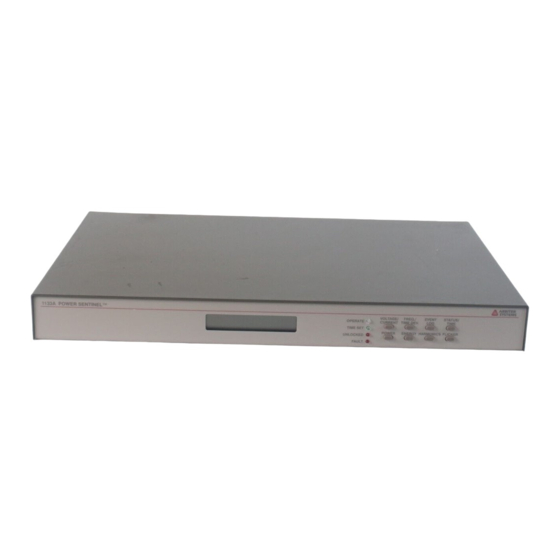
Model 1133A Power Sentinel
RG-6 Cable
Advertisement
Table of Contents

Related Manuals for Arbiter Systems 1133A


Summary of Contents for Arbiter Systems 1133A
- Page 1 MODEL 1133A QUICK SETUP GUIDE Introduction This document covers the initial set up of the Model 1133A. For complete details covering the Model 1133A please consult the operation manual. Download from www.arbiter.com. On the website, search under Products Synchronized Power Measurements Model 1133A Power Sentinel on the product page locate the file under...
- Page 2 Inlet power is supplied from an AC or DC power source to the three-terminal block at the right rear of the 1133A. Identification marks are there for assignment of correct polarity. Caution: Polarity markings are especially important for DC power sources.
- Page 3 Choose a cable/connector to match the specific port being used. Use a network cable to connect to the Ethernet port. There are at least four serial connection options available to the 1133A. A special RS-232 cable and adapter are included: RJ-11 phone cable and RJ-11 to DB-9F adapter.
- Page 4 Before connecting the measured electrical system to the 1133A, consult the operation manual in Chapter 3, which provides a number of common system configurations. Caution: Verify that any input to the 1133A does not exceed maximum ratings - see Chapter 12 for Technical Specifications and Operating Parameters.
Need help?
Do you have a question about the 1133A and is the answer not in the manual?
Questions and answers