Sign In
Upload
Manuals
Brands
Allen-Bradley Manuals
Control Systems
1394C-SJT10-D
Allen-Bradley 1394C-SJT10-D Manuals
Manuals and User Guides for Allen-Bradley 1394C-SJT10-D. We have
1
Allen-Bradley 1394C-SJT10-D manual available for free PDF download: Installation Manual
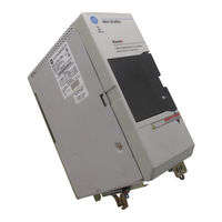
Allen-Bradley 1394C-SJT10-D Installation Manual (131 pages)
Multi-Axis Motion Control System
Brand:
Allen-Bradley
| Category:
Control Systems
| Size: 5.14 MB
Table of Contents
Table of Contents
3
Contents of this Manual
7
Purpose of this Manual
7
Related Documentation
7
Who Should Use this Manual
7
1394 Product Receiving and Storage Responsibility
9
Conventions Used in this Manual
9
Allen-Bradley Support
10
Local Product Support
10
Technical Product Assistance
10
Appendix C Chapter Objectives
11
Chapter Objectives
11
Chapter 1
11
Installing Your 1394 SERCOS Interface System
11
Complying with European Union Directives
12
EMC Directive
12
Low Voltage Directive
12
Before Mounting Your System
13
Storing Your 1394 before Installation
13
Unpacking Modules
13
System Mounting Requirements
14
Determining Your System Mounting Hole Layout
15
Mounting Your 1394 through the Back of the Cabinet
17
Bonding Your System
17
Bonding Modules
17
Bonding Multiple Subpanels
19
Mounting Your 1394 SERCOS Interface System
19
Mounting External Shunt Modules for 22 Kw System Modules
22
Shunt Module Mounting Orientation
23
Shunt Module Mounted Outside the Cabinet
24
Shunt Module Mounted Inside the Cabinet
25
Mounting the Shunt Module
26
Mounting the External Shunt Resistor for
22
Chapter 2
27
Chapter Objectives
27
Connecting Your 1394 SERCOS Interface System
27
Understanding Basic Wiring Requirements
27
Routing High and Low Voltage Cables
28
System Module Wire Sizes
29
Shielding
29
EMI/RFI Shielding
29
EMI/RFI Bonding
29
Input Power Conditioning
30
Determining Your Type of Input Power
31
Grounded Power Configuration
31
Ungrounded Power Configuration
32
Setting the Ground Jumper in a 5 or 10 Kw System Module for Ungrounded Power Configurations
33
Setting the Ground Jumper in a 22 Kw System Module for Ungrounded Power Configurations
34
Grounding Your 1394 SERCOS Interface System
36
Grounding Your System to the Subpanel
36
Grounding Multiple Subpanels
37
Connecting System Module Power
37
Connecting Ground Wires
37
Connector Locations for 5 and 10 Kw System Modules
38
Terminal Block Locations for 22 Kw System Modules
39
Required Tools and Equipment
40
Connecting Power Wiring for 5 and 10 Kw System Modules
40
Connecting Power Wiring for 22 Kw System Modules
41
Connecting Motor Power to Axis Modules
42
Connecting Thermal and Brake Leads to Axis Modules
43
Required Tools and Equipment
44
Wiring Motor Power, Thermals and Brakes
44
Connecting Feedback to System Modules
47
Required Tools and Equipment
48
Connecting Feedback Cables
49
Connecting Your Motor Cables to Motors
52
Scanport Adapter
52
Understanding I/O Connections
53
I/O Signal Pin-Outs
53
I/O Signal Descriptions
55
Wiring I/O Connections
56
Connecting Your SERCOS Fiber Optic Cables
57
Connecting Your Internal Shunt Resistor
58
Connecting Your External Shunt Resistor
59
Connecting Your Shunt Module
60
Required Tools and Equipment
60
Wiring the Shunt Module Power
60
Wiring Shunt Module Fan Power
65
Appendix A
67
Chapter Objectives
67
Specifications
67
System Specifications
67
Certification
67
System Modules
68
AC Line Filters
68
Contact Ratings
69
Axis Modules
69
User-Supplied Contactor (M1
70
User-Supplied Line Input Fusing
70
User-Supplied 24V Logic Input Power
71
Input Transformer for 24V Control Power
71
Circuit Breakers
72
External Shunt Resistor Kit for 5 and 10 Kw Systems
74
1394 Shunt Module for the 22 Kw System
74
Environmental Specifications
75
Power Dissipation
75
System Modules
76
Axis Modules
76
Internal Shunt Resistor for the 5 and 10 Kw System
76
Communication Specifications
77
Dedicated I/O Specifications
77
Dimensions
77
1394 System Module Dimensions
78
Axis Module Dimensions
79
AC Line Filter Dimensions
81
External Shunt Dimensions
83
Motor Dimensions
86
Servo Motor Performance Data
96
MP-Series Performance Data
96
1326AB Performance Data
97
1326AS Performance Data
98
1394 SERCOS Interface Interconnect Diagrams
99
1394 SERCOS Interconnections
100
Appendix B
99
Chapter Objectives
99
Interconnect Diagrams
99
Thermal and Brake Interconnect Diagrams
105
Understanding Motor Thermal Switches
105
Wiring
105
Thermal Switch Interconnect Diagrams
105
Brake Interconnect Diagrams
110
Motor Cable Pin-Outs
114
MP-Series Motor Feedback Cables
114
1326 Motor Feedback Cables
115
MP-Series Motor Power Cables
116
1326 Motor Power Cables
117
Grounding for 1394 CE Requirements
119
1394 System Modules
121
1394 Axis Modules
122
AC Line Filters
122
External Shunt Modules
122
SERCOS Interface Fiber Optic Cables
123
Motor Cables and Connector Kits
124
Miscellaneous Accessories
126
Advertisement
Advertisement
Related Products
Allen-Bradley 1394C-SJT05-D
Allen-Bradley 1394C-SJT22-D
Allen-Bradley 1394 SERCOS
Allen-Bradley 1734-8CFG
Allen-Bradley 1756-RM
Allen-Bradley 1756-RMXT
Allen-Bradley ControlLogix 1756-ENBT
Allen-Bradley 1756-EWEB
Allen-Bradley ControlLogix 1756-CNBR
Allen-Bradley 1756-CNBD
Allen-Bradley Categories
Control Unit
Controller
I/O Systems
Power Supply
Switch
More Allen-Bradley Manuals
Login
Sign In
OR
Sign in with Facebook
Sign in with Google
Upload manual
Upload from disk
Upload from URL