User Manuals: Aerotech ANT130LZ Series Stage
Manuals and User Guides for Aerotech ANT130LZ Series Stage. We have 2 Aerotech ANT130LZ Series Stage manuals available for free PDF download: Hardware Manual

Aerotech ANT130LZ Series Hardware Manual (52 pages)
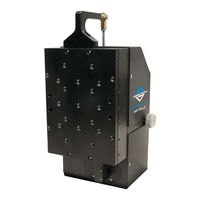
Single-Axis Z Direct-Drive Nanopositioning Stage
Brand: Aerotech
|
Category: Lifting Systems
|
Size: 1 MB
Table of Contents
Advertisement
Aerotech ANT130LZ Series Hardware Manual (40 pages)
Brand: Aerotech
|
Category: Industrial Equipment
|
Size: 1 MB