Table of Contents
Advertisement
Quick Links
Advertisement
Table of Contents

Related Manuals for Aerotech ANT130LZ-035


Summary of Contents for Aerotech ANT130LZ-035
-
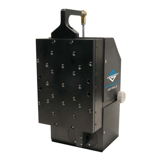
Page 1: Ant130Lz Hardware Manual
ANT130LZ Hardware Manual Revision: 1.01.00... - Page 2 This manual contains proprietary information and may not be reproduced, disclosed, or used in whole or in part without the express written permission of Aerotech, Inc. Product names mentioned herein are used for identification purposes only and may be trademarks of their respective companies.
-
Page 3: Table Of Contents
3.3. Motor and Feedback Specifications 3.4. Limits, Marker, and Machine Direction 3.5. Motor and Feedback Phasing Chapter 4: Maintenance 4.1. Service and Inspection Schedule 4.2. Cleaning and Lubrication 4.3. Troubleshooting Appendix A: Warranty and Field Service Appendix B: Revision History Index www.aerotech.com... -
Page 4: List Of Figures
Counterbalance Pressure vs. External Payload Figure 3-1: Motor and Feedback Wiring [-CN1 option] Figure 3-2: Motor and Feedback Wiring [-CN2 option] Figure 3-3: Machine Direction Figure 3-4: Hall Phasing Figure 3-5: Analog Encoder Phasing Reference Diagram Figure 3-6: Encoder Phasing Reference Diagram (Standard) www.aerotech.com... -
Page 5: List Of Tables
Table 1-2: Environmental Specifications Table 1-3: ANT130LZ Series Specifications Table 3-1: Motor and Feedback Pinouts (-CN1 option) Table 3-2: Motor Pinouts (-CN2 option) Table 3-3: Feedback Pinouts (-CN2 option) Table 3-4: Feedback Specifications Table 3-5: Motor Specifications Table 3-6: Encoder Specifications www.aerotech.com... -
Page 6: Safety Procedures And Warnings
Danger or Warning symbol in this manual. If you do not obey these precautions, injury to you or damage to the equipment can occur. If you do not understand the information in this manual, contact Aerotech Global Technical Support. This product has been designed for light industrial manufacturing or laboratory environments. The protection provided by the equipment could be impaired if the product is used in a manner not specified by the manufacturer. -
Page 7: Eu Declaration Of Incorporation
ANT130LZ Hardware Manual Table of Contents EU Declaration of Incorporation Manufacturer: Aerotech, Inc. 101 Zeta Drive Pittsburgh, PA 15238-2811 herewith declares that the product: ANT130LZ is intended to be incorporated into machinery to constitute machinery covered by the Directive 2006/42/EC as amended;... - Page 8 Table of Contents ANT130LZ Hardware Manual This page intentionally left blank. www.aerotech.com...
-
Page 9: Chapter 1: Overview
Overview Chapter 1: Overview N O T E : Aerotech continually improves its product offerings; listed options may be superseded at any time. All drawings and illustrations are for reference only and were complete and accurate as of this manual’s release. Refer to www.aerotech.com for the most up-to-date information. -
Page 10: Environmental Specifications
Indoor use only 1.2. Accuracy and Temperature Effects Aerotech products are designed for and built in a 20°C (68°F) environment. Extreme temperature changes could cause a decrease in performance or permanent damage to the ANT130LZ. At a minimum, the environmental temperature must be controlled to within 0.25ºC per 24 hours to ensure the ANT130LZ specifications are repeatable over an extended period of time. -
Page 11: Basic Specifications
Overview 1.3. Basic Specifications N O T E : Aerotech continually improves its product offerings; listed options may be superseded at any time. All drawings and illustrations are for reference only and were complete and accurate as of this manual’s release. Refer to www.aerotech.com for the most up-to-date information. -
Page 12: Air Requirements
1.4. Air Requirements It is important to the operation of the ANT130LZ that the air supply meets Aerotech specifications. The air must be filtered to 0.25 microns, dry to 0°F dew point, and oil free (nitrogen at 99.99% purity is recommended). -
Page 13: Chapter 2: Mechanical Specifications And Installation
Allowing it to stabilize to room temperature will ensure that all of the alignments, preloads, and tolerances are the same as they were when tested at Aerotech. Use compressed nitrogen or clean, dry, oil-less air to remove any dust or debris that has collected during shipping. -
Page 14: Dimensions
Mechanical Specifications and Installation ANT130LZ Hardware Manual 2.2. Dimensions Figure 2-2: ANT130LZ Dimensions Chapter 2 www.aerotech.com... -
Page 15: Securing The Stage To The Mounting Surface
Typical tightening torque for an M4 x 0.7 socket head cap screw is 2.0 N·m. b. NOTE: Do not use the two mounting holes located directly below the pneumatics cylinder. 4. Reattach the pneumatics cover by reversing steps used to remove it. Figure 2-3: Mounting Hole Pattern (and Pneumatics Cylinder Clearance) www.aerotech.com Chapter 2... -
Page 16: Setting Up The Pneumatic Counterbalance
Pc = Required counterbalance pressure in MPa (maximum 0.6 MPa allowed) mp = mass of external payload in kg. This relationship is shown graphically in Figure 2-4. Figure 2-4: Counterbalance Pressure vs. External Payload Chapter 2 www.aerotech.com... - Page 17 2. Gently push the carriage down to the bottom of travel until the mechanical shock engages. 3. Turn off the counterbalance pressure. Once the counterbalance pressure has completely bled out, release the hand pressure on the carriage. To change the payload on the stage (add or remove mass), refer to Section 2.4. www.aerotech.com Chapter 2...
-
Page 18: Attaching The Payload To The Stage
N O T E : If your ANT130LZ was purchased with Aerotech controls, it might have been tuned with a representative payload based on the information provided at the time of order. If the ANT130LZ is started up without a payload, the servo gains provided by Aerotech with the shipment may not be appropriate and servo instability can occur. -
Page 19: Chapter 3: Electrical Specifications And Installation
Aerotech motion control systems are adjusted at the factory for optimum performance. When the ANT130LZ is part of a complete Aerotech motion control system, setup usually involves connecting the ANT130LZ to the appropriate drive chassis with the cables provided. Labels on the system components usually indicate the appropriate connections. -
Page 20: Motor And Feedback Connectors
Stages equipped with standard motors and encoders come from the factory completely wired and assembled. N O T E : Refer to the other documentation accompanying your Aerotech equipment. Call your Aerotech representative if there are any questions on system configuration. -
Page 21: Table 3-1: Motor And Feedback Pinouts (-Cn1 Option)
Motor Thermistor Hall Effect sensor, phase B Signal shield connection Motor Phase A Motor Phase B Motor Phase C Case Signal shield connection (to case) Mating Connector Aerotech P/N Third Party P/N Backshell ECK00656 Amphenol #17E-1726-2 Connector ECK00300 FCI DB25S064TLF www.aerotech.com... -
Page 22: Table 3-2: Motor Pinouts (-Cn2 Option)
Motor Phase A Motor Phase B Motor Phase C Reserved Reserved Reserved Reserved Reserved Frame Ground (motor protective ground) Mating Connector Aerotech P/N Third Party P/N Backshell ECK00656 Amphenol #17E-1726-2 Sockets [QTY. 4] ECK00659 ITT Cannon #DM53744-6 Connector ECK00657 ITT Cannon #DBM9W4SA197 Chapter 3 www.aerotech.com... -
Page 23: Table 3-3: Feedback Pinouts (-Cn2 Option)
+5 V power supply Sine Sine-N Reserved Common ground Common ground Reserved Reserved Signal indicating maximum travel produced by negative/CCW stage direction Reserved Mating Connector Aerotech P/N Third Party P/N Backshell ECK00656 Amphenol #17E-1726-2 Connector ECK00300 FCI DB25S064TLF www.aerotech.com Chapter 3... -
Page 24: Motor And Feedback Wiring
All motor and controller manufacturers have their own designations for motor phases A/B/C and Hall signals A/B/C (refer to Section 3.5. for motor phasing). Shielded cables are required for the motor and feedback connections. Figure 3-1: Motor and Feedback Wiring [-CN1 option] Chapter 3 www.aerotech.com... -
Page 25: Figure 3-2: Motor And Feedback Wiring [-Cn2 Option]
ANT130LZ Hardware Manual Electrical Specifications and Installation Figure 3-2: Motor and Feedback Wiring [-CN2 option] www.aerotech.com Chapter 3... -
Page 26: Motor And Feedback Specifications
Requires external pull-up to +5 V (10 kΩ recommended) Notes: If the ANT130LZ is driven beyond the electrical limit, it will encounter a mechanical stop. Impacting the mechanical stop could cause damage to the stage even at low speeds. Chapter 3 www.aerotech.com... -
Page 27: Table 3-5: Motor Specifications
5. All performance and electrical specifications ±10% 6. Maximum winding temperature is 125°C. 7. Ambient operating temperature range 0 °C - 25 °C; consult Aerotech for performance in elevated ambient temperatures 8. All Aerotech amplifiers are rated Apk; use force constant in N·m/Apk when sizing. -
Page 28: Limits, Marker, And Machine Direction
ANT130LZ Hardware Manual 3.4. Limits, Marker, and Machine Direction Aerotech stages are configured to have positive and negative "machine" directions. The machine direction defines the phasing of the feedback and motor signals and is dictated by the stage wiring (refer to Section 3.5. -
Page 29: Motor And Feedback Phasing
ANT130LZ Hardware Manual Electrical Specifications and Installation 3.5. Motor and Feedback Phasing Motor phase voltage is measured relative to the virtual wye common point. Figure 3-4: Hall Phasing www.aerotech.com Chapter 3... -
Page 30: Figure 3-5: Analog Encoder Phasing Reference Diagram
Electrical Specifications and Installation ANT130LZ Hardware Manual Figure 3-5: Analog Encoder Phasing Reference Diagram Figure 3-6: Encoder Phasing Reference Diagram (Standard) Chapter 3 www.aerotech.com... -
Page 31: Chapter 4: Maintenance
Re-tighten loose connectors. Replace or repair damaged cables. Clean the ANT130LZ and any components and cables as needed. Repair any damage before operating the ANT130LZ. Inspect and perform an operational check on all safeguards and protective devices. www.aerotech.com Chapter 4... -
Page 32: Cleaning And Lubrication
W A R N I N G : Further disassembly of the stage is not recommended because proper assembly and calibration can only be done at the factory. In addition, a laser interferometer is required for post assembly verification to maintain warranties. Contact Aerotech for more information. -
Page 33: Troubleshooting
Encoder (sine and cosine) signal connections (refer to Chapter 3 Stage moves Controller documentation). uncontrollably Motor Connections (refer to Chapter 3 and the Controller documentation). Gains misadjusted (refer to the Controller documentation). Stage oscillates or squeals Encoder signals (refer to the Controller documentation). www.aerotech.com Chapter 4... - Page 34 Maintenance ANT130LZ Hardware Manual This page intentionally left blank. Chapter 4 www.aerotech.com...
-
Page 35: Appendix A: Warranty And Field Service
Aerotech makes no warranty that its products are fit for the use or purpose to which they may be put by the buyer, whether or not such use or purpose has been disclosed to Aerotech in specifications or drawings previously or subsequently provided, or whether or not Aerotech’s... - Page 36 Aerotech's approval. On-site Warranty Repair If an Aerotech product cannot be made functional by telephone assistance or by sending and having the customer install replacement parts, and cannot be returned to the Aerotech service center for repair, and if Aerotech determines the problem could be warranty-related, then the following policy applies:...
-
Page 37: Appendix B: Revision History
ANT130LZ Hardware Manual Revision History Appendix B: Revision History Revision General Information 1.01.00 The pneumatic c'balance has been updated to account for pressure drop across the regulator. 1.00.00 New manual / Product update www.aerotech.com Appendix B... - Page 38 Revision History ANT130LZ Hardware Manual This page intentionally left blank. Appendix B www.aerotech.com...
-
Page 39: Index
Pitch Protection Rating Flatness protective ground connection Force Repeatability Global Technical Support Resolution Roll Hall-Effect Sensors Specifications Humidity serial number service schedule In-Position Stability shimming inspection schedule solvents Inspection Schedule Speed isopropyl alcohol stabilizing stage stage label distortion www.aerotech.com Index... - Page 40 Index ANT130LZ Hardware Manual stabilizing Support Technical Support Thermistor Specifications Travel Vibration Warranty and Field Service Index www.aerotech.com...
Need help?
Do you have a question about the ANT130LZ-035 and is the answer not in the manual?
Questions and answers