Sign In
Upload
Manuals
Brands
Aerotech Manuals
Industrial Equipment
ANT130LZS-060
Aerotech ANT130LZS-060 Manuals
Manuals and User Guides for Aerotech ANT130LZS-060. We have
2
Aerotech ANT130LZS-060 manuals available for free PDF download: Hardware Manual
Aerotech ANT130LZS-060 Hardware Manual (52 pages)
Brand:
Aerotech
| Category:
DC Drives
| Size: 1.85 MB
Table of Contents
Table of Contents
3
List of Figures
4
List of Tables
5
EU Declaration of Incorporation
6
Safety Procedures and Warnings
7
Installation and Operation
8
Electrical Warnings
9
Motor-Related Warnings
10
Pinch Points
11
Magnetic Hazards
12
Handling and Storage
13
Chapter 1: Overview
15
Figure 1-1: GEN2 Vs GEN1 Visual Comparison
15
Table 1-1: Model Numbers and Ordering Options
15
Environmental Specifications
16
Accuracy and Temperature Effects
16
Table 1-2: Environmental Specifications
16
Basic Specifications
17
Table 1-3: ANT130LZS Series Specifications
17
Air Requirements
18
Figure 1-2: Counterbalance Air Flow Vs. Counterbalance Pressure
18
Figure 1-3: Air Inlet Location
18
Chapter 2: Installation
19
Dimensions
19
Figure 2-1: ANT130LZS Dimensions
19
Figure 2-2: Mounting Plate (MP) Dimensions
20
Securing the Stage to the Mounting Surface
21
Table 2-1: Stage Mounting Surface Flatness Requirement
21
Figure 2-3: Mounting Hole Pattern
22
Table 2-2: Stage to Mounting Surface Hardware
22
Setting up the Pneumatic Counterbalance
23
Figure 2-4: Counterbalance Pressure Vs. External Payload
23
Attaching the Payload to the Stage
25
Table 2-3: Payload to Stage Surface Hardware
25
Figure 2-5: Load Orientations
26
Figure 2-6: Cantilevered Load Capabilities
27
Chapter 3: Electrical Installation
29
Motor and Feedback Connectors
30
Table 3-1: 25-Pin Motor and Feedback Connector Pinout (-CN1)
31
Table 3-2: 25-Pin Mating Connector Part Numbers
31
Table 3-3: 4-Pin Motor Connector Pinout (-CN2 Option)
32
Table 3-4: 4-Pin Motor Mating Connector Part Numbers
32
Table 3-5: 25-Pin Feedback Connector Pinout (-CN2 Option)
33
Table 3-6: 25-Pin Feedback Mating Connector Part Numbers
33
Motor and Feedback Wiring
34
Figure 3-1: ANT130LZS Motor and Feedback Wiring [-CN1 Option]
34
Figure 3-2: ANT130LZS Motor and Feedback Wiring [-CN2 Option]
35
Motor and Feedback Specifications
36
Table 3-7: Hall-Effect Sensor Specifications
36
Table 3-8: Thermistor Specifications
36
Table 3-9: Encoder Specifications
36
Table 3-10: Limit Switch Specifications
36
Table 3-11: ANT130LZS Motor Specifications
37
Table 3-12: Encoder Resolution
37
Limits, Marker, and Machine Direction
38
Figure 3-3: Machine Direction
38
Motor and Feedback Phasing
39
Figure 3-4: Hall Phasing Diagram
39
Figure 3-5: Encoder Phasing Reference Diagram (Standard/Square Wave)
40
Figure 3-6: Encoder Phasing Reference Diagram (Analog/Sine Wave)
40
Chapter 4: Maintenance
41
Service and Inspection Schedule
41
Cleaning and Lubrication
42
Counterbalance Maintenance
44
Troubleshooting
45
Appendix A: Warranty and Field Service
47
Appendix B: Revision History
49
Index
51
Advertisement
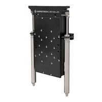
Aerotech ANT130LZS-060 Hardware Manual (46 pages)
Brand:
Aerotech
| Category:
Industrial Equipment
| Size: 4.25 MB
Table of Contents
ANT130LZS Hardware Manual
1
Table of Contents
3
List of Figures
4
List of Tables
5
Safety Procedures and Warnings
6
EU Declaration of Incorporation
7
Chapter 1: Overview
9
Figure 1-1: ANT130LZS
9
Table 1-1: ANT130LZS Model Numbering System
9
Accuracy and Temperature Effects
10
Environmental Specifications
10
Table 1-2: Environmental Specifications
10
Basic Specifications
11
Table 1-3: ANT130LZS Series Specifications (-035 and -060)
11
Table 1-4: ANT130LZS Series Specifications (-110 and -160)
12
Air Requirements
13
Figure 1-2: Counterbalance Air Flow Vs. Counterbalance Pressure
13
Chapter 2: Mechanical Specifications and Installation
15
Unpacking and Handling the Stage
15
Figure 2-1: Shipping Clamps
15
Dimensions
16
Figure 2-2: ANT130LZS Dimensions
16
Securing the Stage to the Mounting Surface
17
Figure 2-3: Mounting Hole Pattern
18
Figure 2-4: Mounting Pattern
19
Setting up the Pneumatic Counterbalance
20
Figure 2-5: Counterbalance Pressure Vs. External Payload
20
Attaching the Payload to the Stage
22
Figure 2-6: Load Orientations
23
Figure 2-7: Cantilevered Load Capabilities
24
Chapter 3: Electrical Specifications and Installation
25
Motor and Feedback Connectors
26
Table 3-1: Motor and Feedback Pinouts (-CN1 Option)
27
Table 3-2: Motor Pinouts (-CN2 Option)
28
Table 3-3: Feedback Pinouts (-CN2 Option)
29
Motor and Feedback Wiring
30
Figure 3-1: Motor and Feedback Wiring [-CN1 Option]
30
Figure 3-2: Motor and Feedback Wiring [-CN2 Option]
31
Motor and Feedback Specifications
32
Table 3-4: Feedback Specifications
32
Table 3-5: Motor Specifications
33
Table 3-6: Encoder Specifications
33
Limits, Marker, and Machine Direction
34
Figure 3-3: Machine Direction
34
Motor and Feedback Phasing
35
Figure 3-4: Hall Phasing
35
Figure 3-5: Analog Encoder Phasing Reference Diagram
36
Chapter 4: Maintenance
37
Service and Inspection Schedule
37
Cleaning and Lubrication
38
Troubleshooting
39
Appendix A: Warranty and Field Service
41
Appendix B: Revision History
43
Index
45
Advertisement
Related Products
Aerotech ANT130LZS Series
Aerotech ANT130LZS-035
Aerotech ANT130LZS-160
Aerotech ANT130LZS-110
Aerotech ANT130LZ-035
Aerotech ANT130LZ Series
Aerotech ANT130LZ-060
Aerotech ANT130R-360
Aerotech ANT130R-020
Aerotech ANT130R-180
Aerotech Categories
Industrial Equipment
DC Drives
Controller
Engine
Valve Positioners
More Aerotech Manuals
Login
Sign In
OR
Sign in with Facebook
Sign in with Google
Upload manual
Upload from disk
Upload from URL