Sign In
Upload
Manuals
Brands
ADLINK Technology Manuals
Control Unit
HSL-4XMO
ADLINK Technology HSL-4XMO Manuals
Manuals and User Guides for ADLINK Technology HSL-4XMO. We have
1
ADLINK Technology HSL-4XMO manual available for free PDF download: User Manual
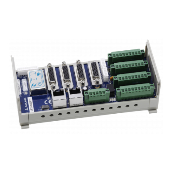
ADLINK Technology HSL-4XMO User Manual (112 pages)
High Speed Link 4-Axis Motion Control Module
Brand:
ADLINK Technology
| Category:
Control Unit
| Size: 1 MB
Table of Contents
Table of Contents
5
List of Tables
8
1 Introduction
11
Features
12
Specifications
13
Supported Software
15
Programming Library
15
Motion Creator on Linkmaster Utility
15
2 Installation
17
Package Contents
17
Pin Assignments and Jumper Settings
18
Figure 2-1: HSL-4XMO-CG-N/P Mechanical Drawing
18
Table 2-1: CN1 Pin Assignments: External Power Input
19
Table 2-2: CN2 Pin Assignments: Emergency Input and General Input Common
19
Table 2-3: HS1-HS2 Pin Assignments: HSL Communication Signal (RJ-45)
19
Table 2-4: HS3 Pin Assignments: HSL Communication Signal
19
Table 2-5: CM1-CM4 Pin Assignments: Servo Interface
20
Table 2-6: IOIF1-4 Pin Assignments: Mechanical I/O and GPIO Signal Connector
20
Figure 2-2: S1: Switch Setting for HSL Slave ID
21
Figure 2-3: JP1: HSL Communication Speed Selection Jumper Set
21
Figure 2-4: P2-3: HSL Full Duplex/Half Duplex Jumper Setting
22
Figure 2-5: JP4: HSL Termination Resistor Jumper Setting
22
3 Signal Connections
23
Pulse Output Signals out and dir
24
Figure 3-1: out and dir Signals on the 4 Axes
24
Figure 3-2: Non-Differential Type Wiring Example
25
Encoder Feedback Signals EA, EB and EZ
26
Figure 3-3: EA, EB, and EZ Signals
26
Table 3-1: Encoder Power / External Resistor
27
Figure 3-4: Connection to Line Driver Output
27
Origin Signal ORG
28
Figure 3-5: Connection to Open Collector Output
28
Figure 3-6: Origin Signal ORG
28
End-Limit Signals PEL and MEL
29
Ramping-Down & Position Latch
29
Figure 3-7: End-Limit Signals PEL and MEL
29
In-Position Signal INP
30
Figure 3-8: Ramping-Down & Position Latch
30
Figure 3-9: In-Position Signal INP
30
Alarm Signal ALM
31
Deviation Counter Clear Signal (ERC)
31
Figure 3-10: Alarm Signal ALM
31
General-Purpose Signal SVON
32
General-Purpose Signal RDY
32
Figure 3-11: Deviation Counter Clear Signal (ERC)
32
Figure 3-12: General-Purpose Signal SVON
32
Position Compare Output CMP
33
Emergency Stop Input EMG
33
Figure 3-13: General-Purpose Signal RDY
33
Figure 3-14: Position Compare Output CMP
33
General-Purpose Input
34
General-Purpose Output
34
Figure 3-15: Emergency Stop Input EMG
34
Figure 3-16: General-Purpose Input
34
Figure 3-17: NPN Type General Purpose Output
35
Figure 3-18: PNP Type General Purpose Output
35
4 Operation Theory
37
Communication Block Diagram
37
Host Command
37
Figure 4-1: Communication Block Diagram
37
Command Delivering Time
38
Table 4-1: Base Scan Times
39
Figure 4-2: Single Command Timing
39
Command Dispatching in DSP
40
Figure 4-3: DSP Multi-Tasks
40
The Role of DSP and Motion ASIC
41
Motion Control Modes
41
Pulse Command Output
41
Table 4-2: Pulse Command Output
41
Figure 4-4: Single Pulse Output Mode (OUT/DIR Mode)
42
Velocity Mode Motion
43
Figure 4-5: Dual Pulse Output Mode (CW/CCW Mode)
43
Trapezoidal Motion
44
Figure 4-6: Velocity Mode Motion
44
Figure 4-7: Trapezoidal Motion
45
S-Curve Profile Motion
47
Figure 4-8: Encoder Diagram
47
Figure 4-9: S-Curve Profile Motion
48
Figure 4-10: Automatic Velocity Decrease
49
Linear Interpolation for 2-4 Axes
50
Table 4-3: Single Axis Motion Functions
50
Figure 4-11: 2 Axes Linear Interpolation
51
Figure 4-12: 3-Axis Linear Interpolation
52
Circular Interpolation for 2 Axes
54
Figure 4-13: Circular Interpolation for 2 Axes
54
Circular Interpolation with Acc/Dec Time
55
Relationship between Velocity and Acceleration Time
56
Figure 4-14: Circular Interpolation with Acc/Dec Time
56
Figure 4-15: Velocity and Acceleration Time a
57
Figure 4-16: Velocity and Acceleration Time B
58
Home Return Mode
59
Figure 4-17: Home_Mode=0
60
Figure 4-18: Home_Mode=1
61
Figure 4-19: Home_Mode=3
61
Figure 4-20: Home_Mode=4
62
Figure 4-21: Home_Mode=5
63
Figure 4-22: Home_Mode=6
63
Figure 4-23: Home_Mode=7
63
Figure 4-24: Home_Mode=8
64
Figure 4-25: Home_Mode=9
64
Figure 4-26: Home_Mode=10
65
Figure 4-27: Home_Mode=11
66
Figure 4-28: Home_Mode=12
66
Figure 4-29: Home Search Example
67
The Motor Driver Interface
69
Inp
69
Alm
70
Erc
70
SVON and RDY
71
The Limit Switch Interface and I/O Status
72
Sd/Ltc
72
Org
73
The Counters
74
Command Position Counter
74
Feedback Position Counter
75
Figure 4-30: 90° Phase Difference Signals
76
Position Error Counter
77
General Purpose Counter
77
Target Position Recorder
78
Table 4-4: Counter Summary
78
Multiple HSL-4XMO Operations
79
Table 4-5: Multiple HSL-4XMO Operations
79
Change Position or Speed on the Fly
80
Change Speed on the Fly
80
Figure 4-31: Change Speed on the Fly
80
Figure 4-32: Hsl_M_V_Change() Theory
82
Table 4-6: Hsl_M_V_Change() Example
83
Figure 4-33: Velocity Suggestions a
83
Figure 4-34: Velocity Suggestions B
84
Figure 4-35: Velocity Example
84
Figure 4-36: Velocity Profile Example
85
Change Position on the Fly
86
Figure 4-37: Change Position on the Fly
86
Figure 4-38: Theory of Hsl_M_P_Change()
87
Position Compare
88
Comparators of the HSL-4XMO
88
Table 4-7: Hsl_M_P_Change() Constraints
88
Table 4-8: HSL-4XMO Comparators
88
Position Compare
89
Figure 4-39: Continuously Comparison with Trigger Output
90
Backlash Compensator and Vibration Suppression
92
Figure 4-40: Vibration Suppression
92
Software Limit Function
93
Point Table Management
93
Motion Script Download
94
5 Motion Creator in Linkmaster
95
Execute Motion Creator in Linkmaster
95
About Motion Creator in Linkmaster
95
Figure 5-1: HSL Master Utility
96
Motion Creator Form Introducing
97
Main Menu
97
Figure 5-2: Main Menu
97
Interface I/O Configuration Menu
98
Figure 5-3: Interface I/O Configuration Menu
98
Pulse IO Configuration Menu
99
Figure 5-4: Pulse IO Configuration Menu
100
Operation Menu
101
Figure 5-5: Operation Menu
102
Figure 5-6: Show Velocity Curve
103
Figure 5-7: Home Mode Configuration
104
6 Appendix
109
HSL-4XMO Commmand Executuion Time
109
Table 6-1: Commmand Executuion Classifications
109
Table 6-2: HSL-4XMO Commmand Executuion Times
109
Warranty Policy
111
Advertisement
Advertisement
Related Products
ADLINK Technology HSLink HSL-DI32
ADLINK Technology HSLink HSL-DO32
ADLINK HSLink HSL-AO4
ADLINK Technology HSLink HSL-R8DI16
ADLINK Technology HSLink HSL-DI16DO16
ADLINK Technology HSLink HSL-AI16
ADLINK Technology HDV62A
ADLINK Technology HPERC-KBL-MH
ADLINK Technology HPERC-IBR-MC
ADLINK Technology HPERC-IBR-MH
ADLINK Technology Categories
Computer Hardware
Motherboard
PCI Card
Control Unit
Desktop
More ADLINK Technology Manuals
Login
Sign In
OR
Sign in with Facebook
Sign in with Google
Upload manual
Upload from disk
Upload from URL