ABB TTH300 Series Manuals
Manuals and User Guides for ABB TTH300 Series. We have 9 ABB TTH300 Series manuals available for free PDF download: Commissioning Instructions, Operating Instruction, Instructions Manual, User Manual, Safety Instructions, Operating Instructions Manual

ABB TTH300 Series Commissioning Instructions (284 pages)
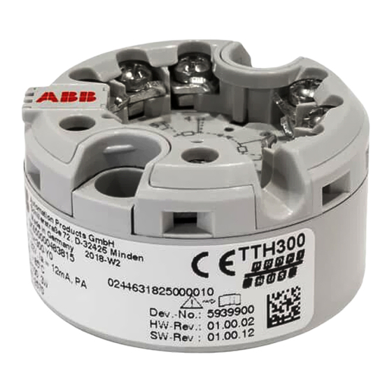
Head mounted Temperature Transmitter
Brand: ABB
|
Category: Transmitter
|
Size: 3 MB
Table of Contents
Advertisement
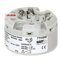
ABB TTH300 Series Operating Instruction (64 pages)
Head-mount temperature transmitter
Brand: ABB
|
Category: Transmitter
|
Size: 2 MB
Table of Contents

ABB TTH300 Series Operating Instruction (74 pages)
Head mounted Temperature Transmitter
Brand: ABB
|
Category: Transmitter
|
Size: 1 MB
Table of Contents
Advertisement

ABB TTH300 Series Operating Instruction (76 pages)
Head-mount temperature transmitter
Brand: ABB
|
Category: Transmitter
|
Size: 2 MB
Table of Contents
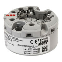
ABB TTH300 Series Operating Instructions Manual (20 pages)
Head-mount temperature transmitter
Brand: ABB
|
Category: Transmitter
|
Size: 0 MB
Table of Contents

ABB TTH300 Series Instructions Manual (26 pages)
Brand: ABB
|
Category: Transmitter
|
Size: 0 MB
Table of Contents

ABB TTH300 Series User Manual (24 pages)
H Series temperature transmitter
Brand: ABB
|
Category: Transmitter
|
Size: 1 MB
Table of Contents

ABB TTH300 Series Safety Instructions (22 pages)
Brand: ABB
|
Category: Temperature Controller
|
Size: 1 MB
Table of Contents

ABB TTH300 Series Safety Instructions (24 pages)
Temperature Transmitter, SILl 2 / 3
Brand: ABB
|
Category: Transmitter
|
Size: 2 MB
Table of Contents
Advertisement