
Related Manuals for Nikon Eclipse LV100DA-U


Summary of Contents for Nikon Eclipse LV100DA-U
- Page 1 M421 E 07.5.NF.1 (2/3) Universal Design Microscope UDM ECLIPSE LV100DA-U Instructions...
-
Page 3: Warning And Caution Symbols Used In This Manual
Microscope UDM ECLIPSE LV100DA-U. To ensure correct usage, read this manual carefully before operating the product. • It is prohibited to reproduce or transmit this manual in part or whole without Nikon’s expressed permission. • The contents of this manual are subject to change without notice. -
Page 4: Warning
Nikon TE2-PS100W Power Supply (model name: TE2-PS100W) This power supply is connected to the lamp house for the episcopic illumination to turn on the episcopic illumination and the diascopic illumination simultaneously. If you wish to buy these lamps, please contact your nearest Nikon representative. - Page 5 LV-UEPI2A epi illuminator. • Light source Nikon Inensilight C-HGFIE HG Precentered Illuminator (model name: C-HGFIE, electric operation type) or X-Cite 120 PC (electric operation type) made by EXFO Electro Optical Engineering Inc. If a manual operation type light source is attached, you cannot control the shutter and the brightness on the microscope.
-
Page 6: Caution
If water enters a component, immediately suspend use of this product, disconnect the power cord from the outlet, and contact your nearest Nikon representative. 3. Weak electromagnetic waves The product emits weak electromagnetic waves. The accuracy of any precision electronic equipment may be adversely affected if positioned too close. - Page 7 CAUTION 7. Cable routing Make sure the cables are routed properly. Do not bring the cables into contact with the lamp house for the diascopic illumination. If a cable comes into contact with the lamp house, the cable sheath may melt and it results in an electrical shock or fire. 8.
-
Page 8: Table Of Contents
CONTENTS WARNING and CAUTION Symbols Used in This Manual ......... 1 Meaning of Symbols Used on the Product ............1 WARNING ......................2 CAUTION ......................4 Part Name ..................... 8 1 Configuration of the Product and Control Names .............. 8 2 To Perform Epi/Dia Simultaneous Illumination ............... - Page 9 CONTENTS 16 Analyzer Slider ......................... 60 17 PA Block ........................... 61 18 Lambda Plate Slider for the Episcopic Illumination ............62 19 Lambda Plate Slider for the Diascopic Illumination ............63 20 DIC Prism (For the Episcopic Illumination/Senarmont Method) ........64 21 DIC Prism (For the Episcopic Illumination/Prism Slide Method) ........
-
Page 10: Part Name
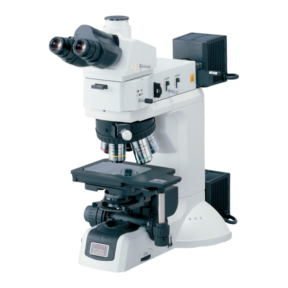
Configuration of the Product and Control Names Front left side of the microscope This drawing depicts the ECLIPSE LV100DA-U microscope configured with the LV-UEPI2A epi illuminator, the LV-TT2 eyepiece tube, the LV-NU5AI motorized nosepiece, the 3x2 stage, the glass slide holder, the diascopic illumination condenser (the slide condenser), the lamp house for the episcopic illumination, the lamp house for the diascopic illumination, and attachments for the DIC microscopy. - Page 11 I. Part Name Front right side of the microscope Clamp screw for Optical path selector lever various adapters Analyzer slider Eyepiece Polarizer slider Dummy slider Diopter adjustment ring Connection cable for the LV-UEPI2A Microscopy method indicator F . S T O Aperture diaphragm centering screw DF FL1 FL2...
-
Page 12: To Perform Epi/Dia Simultaneous Illumination
To Perform Epi/Dia Simultaneous Illumination The drawing below depicts the LV100DA-U microscope configuration to use the episcopic illumination and the diascopic illumination simultaneously. To turn on the both illumination simultaneously, the lamp house for the episcopic illumination must be connected to an external power supply (TE2- PS100W). -
Page 13: Operation Panel
I. Part Name Operation Panel On the operation panel, there are switches to operate electric operation parts in the microscope. EPI switch EPI brightness level indicator CUBE switch EPI brightness switch OBJ.switch DIA brightness level indicator A.S. OBJ. CUBE DIA brightness switch A.S. -
Page 14: Rear View
I. Part Name Rear View This drawing depicts the Eclipse LV100DA-U microscope configured with the LV-UEPI2A epi illuminator, the LV-TT2 eyepiece tube, the 3x2 stage, the lamp house for the episcopic illumination, and the lamp house for the diascopic illumination “CAUTION for heat”... -
Page 15: Microscopy Method
Microscopy Method CAUTION Before performing microscopy • Before using the microscope, please set up the LV100DA-U using “LVSetup” on a PC contained in “LV Series Support Tools.” • In this chapter, the microscopy is described with the interlock control of LVSetup set to the Default mode. - Page 16 Microscopy methods list See the table below for the microscopies available with the product, as well as the optional accessories required for each microscopy. Microscopy Microscopy Required accessories (optional) Method Bright-field microscopy under p.15 — the epi-illumination Dark-field microscopy under p.17 BD objective the epi-illumination...
-
Page 17: Bright-Field Microscopy Under The Epi Illumination
II. Microscopy Method Bright-field Microscopy under the Epi Illumination Turn on the power switch. When the power to the microscope is turned on, the Turn on the power. microscope starts initialization. And then, the power Achr Power indicator on the microscope base is lit. (See Page 34.) indicator OBJ . - Page 18 Adjust the angle of the binocular eyepiece. Adjust the angle of the (for the LV-TT2) binocular eyepiece. (See Page 48.) Adjust the diopter and the interpupillary F. ST OP distance. Adjust the DF FL1 FL2 diopter and the UEP I2A (See Page 49.) interpupillary distance.
-
Page 19: Dark-Field Microscopy Under The Epi Illumination
II. Microscopy Method Dark-field Microscopy under the Epi Illumination Attach the accessories required for the dark-field microscopy under the epi illumination. The following accessories must be attached to perform the dark-field microscopy under the epi illumination. • BD objective (See Page 93.) * Set up the microscope according to the “LVSetup”... -
Page 20: Polarization Microscopy Under The Epi Illumination (Simplified/Sensitive Color)
Polarization Microscopy under the Epi Illumination (Simplified/Sensitive Color) Attach the accessories required for the polarization microscopy under the epi illumination. The following accessories must be attached to the LV-UEPI2A to perform the polarization microscopy under the epi illumination. • Polarizer slider (See Page 83.) •... - Page 21 II. Microscopy Method Return to the bright-field microscopy under the epi illumination. 1 Pull out the analyzer slider and move the F. ST OP analyzer away from the optical path. DF FL1 FL2 (See Page 60.) UEP I2A 2 Pull out the polarizer slider and move the RS2 32C polarizer away from the optical path.
-
Page 22: Differential Interference Contrast Microscopy Under The Epi Illumination (Senarmont Method)
Differential Interference Contrast Microscopy under the Epi Illumination (Senarmont Method) Methods of the differential interference contrast (DIC) microscopy vary among the nosepiece configuration. For the standard LV-NU5AI nosepiece, the Senarmont method is used for the DIC microscopy under the epi illumination. Attach the accessories required for the Senarmont method of the DIC microscopy . - Page 23 II. Microscopy Method 5 Rotate the rotation ring of the polarizer slider to adjust the contrast. (See Page 57.) The polarizer slider is equipped with the 1/4 lambda plate so that the contrast can be adjusted by adjusting the orientation of the polarizer. 6 To perform the sensitive color microscopy, push in the lambda plate slider to place the lambda plate into the optical path.
-
Page 24: Differential Interference Contrast Microscopy Under The Epi Illumination (Prism Slide Method)
Differential Interference Contrast Microscopy under the Epi Illumination (Prism Slide Method) Methods of the differential interference contrast (DIC) microscopy vary among the nosepiece configuration. For motorized universal quintuple nosepieces, the LV-NU5A and the LV-NU5AC, the prism slide method is used for the DIC microscopy under the epi illumination. Attach the accessories required for the prism slide method of the DIC microscopy under the episcopic illumination. - Page 25 II. Microscopy Method 5 Set the prism selector knob of the DIC slider to the position (A or B) indicated on the body of the Set the prism selector CF Plan objective. (See Page 65.) 10X/ knob to the position 0.30 /0 BD DIC indicated on the objective.
-
Page 26: Epi-Fl Microscopy
Epi-fl Microscopy Attach the accessories required for the epi-fl microscopy. The following accessories must be attached to perform the epi-fl microscopy. • Filter cube for the epi-fl microscopy (attached to the LV-UEPI2A) (See Page 84.) • External light source (Intensilight C-HGFIE or EXFO X-Cite 120 PC, used when the brightness of the halogen lamp is insufficient.) (See Page 89.) * If only the simplified polarization microscopy is performed, the PA block (LV-PAB) can be used instead of the analyzer and the polarizer. - Page 27 II. Microscopy Method Return to the bright-field or dark-field microscopy under the epi illumination. 1 Press the CUBE switch on the operation panel F. ST OP and light up the “BF (bright-field)” or “DF (dark-field)” position of the microscopy method DF FL1 FL2 UEP I2A indicator.
-
Page 28: Bright-Field Microscopy Under The Dia Illumination
Bright-field Microscopy under the Dia Illumination Turn on the power switch. When the power to the microscope is turned on, the Turn on the power. microscope starts initialization. And then, the power Achr Power indicator on the microscope base is lit. (See Page 34.) indicator OBJ . - Page 29 II. Microscopy Method Place the specimen onto the stage and focus on it. Set the specimen onto the stage and adjust the focus. 1 Lower the stage by turning the coarse/fine focus knobs. (See Page 46.) Achr 2 Set the specimen onto the stage. To use the glass slide, be sure to set the specimen in place with the cover glass facing up.
-
Page 30: Polarization Microscopy Under The Dia Illumination (Simplified/Sensitive Color)
Polarization Microscopy under the Dia Illumination (Simplified/Sensitive Color) Attach the accessories required for the polarization microscopy under the dia illumination. The following accessories must be attached to perform the simplified/sensitive color polarization microscopy under the dia illumination. • Diascopic slider (See Page 94.) •... -
Page 31: Dark-Field Microscopy Under The Dia Illumination
II. Microscopy Method Dark-field Microscopy under the Dia Illumination Attach the accessories required for the dark-field microscopy under the dia illumination. The following accessories must be attached to perform the simplified/sensitive color dark-field microscopy under the dia illumination. • Universal condenser (dry) and dark-field annular diaphragm (See Page 78 and the LV-CUD instruction manual.), or dark-field condenser (See Page 78.) Focus on the specimen with the bright-field microscopy under the diascopic illumination. -
Page 32: Phase Contrast Microscopy Under The Dia Illumination
Phase Contrast Microscopy under the Dia Illumination Note on the phase contrast microscopy under the Diascopic illumination The view of a phase contrast image depends on the phase contrast characteristics or the shape of the specimen and the characteristic of the objective. For details about the phase contrast microscopy, refer to the LV-CUD Instruction manual. - Page 33 II. Microscopy Method Return to the bright-field microscopy under the diascopic illumination. 1 Press the OBJ. switch on the operation panel and locate the objective of a desired magnification into the optical path. (See Page 43.) 2 Rotate the condenser turret of the universal F.
-
Page 34: Differential Interference Contrast Microscopy Under The Dia Illumination
Differential Interference Contrast Microscopy under the Dia Illumination The Senarmont method is used for the DIC microscopy under the dia illumination. Attach the accessories required for the DIC microscopy under the dia illumination. The following accessories must be attached to perform the DIC microscopy under the dia illumination. •... - Page 35 II. Microscopy Method 8 Adjust the field diaphragm and the aperture diaphragm. • Generally, decrease the size of the aperture diaphragm to approximately 70 to 80% of the numerical aperture of the objective. (See Page 54.) • Decrease the size of the field diaphragm so that it inscribes or circumscribes the viewfield. (See Page 54.) 9 Adjust the orientation of the polarizer by rotating the rotatable polarizer for the diascopic illumination and adjust the contrast of DIC contrast images.
-
Page 36: Operation Of Each Part
Operation of Each Part CAUTION • Before using the microscope, please set up the entire system of the microscope with a PC using “LVSetup” contained in “LV Series Support Tools.” • For details about operations of the “LVSetup,” see “LV Series Support Tools software manual.”... - Page 37 III. Operation of Each Part Power supply of the external power supply When the lamp house is connected to the external power supply (TE2-PS100W), please turn on the power as follows. 1 Check that the lamp house has been properly POWER Power connected to the external power supply.
-
Page 38: Setting Up The Microscope
Setting Up the Microscope When you use the product for the first time and when an objective or a device of the product is changed, you must connect a PC to the product and perform the setup work with the designated software for various settings. -
Page 39: Selecting The Microscopy Method
III. Operation of Each Part Selecting the Microscopy Method Switching between the epi illumination and the dia illumination To switch between the epi illumination and the dia illumination, operate the EPI switch and the DIA EP I EP I OB J. switch of the operation panel. - Page 40 Details on the microscopy methods under the episcopic illumination The following microscopy methods can be performed with this microscope. f - t e i f r c i – u l l o i t l i f r e t l i i c i t e t l...
- Page 41 III. Operation of Each Part Details on the microscopy methods under the diascopic illumination The following microscopy methods can be performed. f - t f - t i t a i t a f - t i t a f i l f - t i t a a t t...
- Page 42 Interlock control linked to the microscopy method CAUTION To perform the interlock function properly, you must register the microscope configuration and the objective information correctly. The interlock control is a function to change the electrically-driven devices of the microscope to the pre-determined condition referring to the microscopy method and the objective when the microscopy method or the objective is changed.
-
Page 43: Illumination
III. Operation of Each Part Illumination NIS-Elements compatible Illumination on/off Power indicator Use the EPI switch and the DIA switch on the operation panel to turn on and off the illumination. The EPI switch and the DIA switch turn on/off the episcopic illumination EP I EP I and diascopic illumination respectively. - Page 44 Brightness control NIS-Elements compatible To control the brightness, use the EPI or DIA brightness switch. Independent switches are available each for the episcopic illumination and diascopic illumination to control the brightness, and the current EP I brightness is indicated with the eight-step level EP I OB J.
-
Page 45: Objective
III. Operation of Each Part Objective NIS-Elements compatible Rotating the nosepiece To change the objective by rotating the electrical nosepiece, press the OBJ. switch on the operation panel. The OBJ. switch is divided into two parts. Press the upper switch to rotate the electrical nosepiece in the clockwise direction (when seen from above), and press the lower button to rotate the electrical nosepiece in the counterclockwise direction (when... -
Page 46: Filter
Filter Filter for the episcopic illumination Two filter sliders are located near the rear side of the epi illuminator. Each slider can hold two filters. Push in or pull out the filter sliders to locate the desired filters. See Page 83 for the filter attaching method. Filters Usage NCB11... -
Page 47: Stage
III. Operation of Each Part Stage Stage operation The 3x2 stage, the 6x4 stage, the 6x6 stage, the rectangular stage, and the rotatable rectangular stage are equipped with stage fine movement knobs. The upper knob is used for the Y-axis and the lower knob Fine movement knob is used for the X-axis. -
Page 48: Coarse Focus Knob And Fine Focus Knob
Coarse Focus Knob and Fine Focus Knob Knob rotation and stage vertical movement The relationship between the direction of coarse/fine focus knob rotation and the stage vertical movement is shown in the right figure. • One revolution of the coarse focus knob drives the stage approximately 14.0 mm. - Page 49 III. Operation of Each Part Coarse focus stopper The coarse focus stopper restricts the movement of the coarse focus knob so that the stage cannot be raised higher than the position the operator specifies. When the coarse focus stopper ring is rotated in the direction of the arrow (labeled “CLAMP →”) on the microscope base, the stage cannot move higher than that position.
-
Page 50: Eyepiece Tube
Eyepiece Tube Optical path selection The distribution of light for the binocular part and the vertical tube can be selected with the optical path selector lever. Distribution of light Distribution of light Lever Lever position position Binocular part Vertical tube Binocular part Vertical tube 100 % 100 %... -
Page 51: Diopter Adjustment
III. Operation of Each Part Diopter Adjustment Diopter adjustment compensates for the difference in visual acuity between the right and left eyes. This adjustment improves binocular observation and minimizes focal deviation when switching objectives. Make sure to adjust the diopter adjustment rings on both eyepieces. 1 Rotate the diopter adjustment rings of the eyepieces and align their engraved lines with the edges of the outer tubes of the eyepieces (They are the standard positions for the diopter rings.) 2 Follow the procedure described in Pages 15 and 16 for the bright-field microscopy under the... -
Page 52: Adjustment For The Episcopic Illumination (Field Diaphragm And Aperture Diaphragm)
Adjustment for the Episcopic Illumination (Field Diaphragm and Aperture Diaphragm) Field diaphragm The field diaphragm restricts the illumination light to the area on the specimen to be observed. The field diaphragm Image of the open/close lever changes the opening of the field field diaphragm diaphragm. - Page 53 III. Operation of Each Part Aperture diaphragm Pupil of the objective NIS-Elements compatible The aperture diaphragm controls the numerical aperture of the illumination system, closely related to the 70% to 80% 70% to 80% 70% to 80% resolution of the optical image, contrast, and depth of focus.
- Page 54 • Interlock control of the aperture diaphragm for the episcopic illumination When the interlock control is enabled with “LVSetup,” the opening of the aperture diaphragm for the episcopic illumination is changed in connection with the microscopy switching and the objective switching. When the interlock control is set to the “Default mode,”...
-
Page 55: Adjustment For The Diascopic Illumination (Focusing And Centering The Condenser And Adjusting The Field Diaphragm And Aperture Diaphragm)
III. Operation of Each Part Adjustment for the Diascopic Illumination (Focusing and Centering the Condenser and Adjusting the Field Diaphragm and Aperture Diaphragm) Focusing and centering the condenser When this microscope is used for the first time or after the condenser lens is replaced, focus and center the condenser so that the light through the condenser is focused on the correct position of the specimen surface (at the center of the optical path). -
Page 56: Aperture Diaphragm
Field diaphragm Image of the field diaphragm The field diaphragm restricts the illumination light to the area on the specimen to be observed. The field diaphragm control on the right side of the microscope changes the opening of the field diaphragm. Adjust the opening of the diaphragm until it circumscribes the field of view. - Page 57 III. Operation of Each Part Slide condenser When the slide condenser is used, vignetting in the field is seen with the 2.5x objective: therefore, the slider 0. 8 0. 7 Ach r N.A = 0.9 0.5 0.4 JAPAN 0.3 0.2 0.1 should be kept inserted.
-
Page 58: Polarizer Slider (For The Episcopic Illumination)
Polarizer Slider (for the Episcopic Illumination) Polarizer sliders The three polarizer sliders as shown below can be used for the product. Polarizer Application Remark Polarization microscopy under the episcopic illumination (simplified/sensitive color) LV-PO polarizer DIC microscopy under the episcopic illumination (prism slide method) DIC microscopy under the episcopic Equipped with the 1/4 LV-UPO polarizer... - Page 59 III. Operation of Each Part Placing the polarizer into the optical path • Attaching the polarizer: Remove the vertically First clickstop position Second clickstop position oriented cover at the right side of the illuminator. And then, insert the polarizer slider into the rear slot with Polarizer rotating dial its orientation indication facing toward the eyepieces.
-
Page 60: Polarizer For The Diascopic Illumination
Polarizer for the Diascopic Illumination Polarizer for the diascopic illumination The following two types of polarizers for the diascopic illumination can be used for the product. Polarizer Application Remark C-SP polarizer for the Polarization microscopy under the diascopic Provided with the swing-out diascopic illumination illumination (simplified/sensitive color) mechanism... - Page 61 III. Operation of Each Part Attaching the D-DP polarizer for the diascopic illumination and adjusting the orientaion Rotatable polarizer for Place the rotatable polarizer for the diascopic illumination the diascopic illumination over the field lens at the microscope base with the polarizer index facing the front and secure it with the clamp screw.
-
Page 62: Analyzer Slider
Analyzer Slider The polarization microscopy under the episcopic illumination First clickstop position Second clickstop position can be performed when the analyzer slider is used with the polarizer slider for the episcopic illumination, and the polarization microscopy under the episcopic illumination can be performed when the analyzer slider is used with the polarizer for the diascopic illumination. -
Page 63: Pa Block
III. Operation of Each Part PA Block When the microscopy under the episcopic illumination is Analyzer performed, even if the polarizer slider and the analyzer slider are not used, crossed Nicols position can easily be L V - P obtained by placing LV-PAB PA block into the optical path. -
Page 64: Lambda Plate Slider For The Episcopic Illumination
Lambda Plate Slider for the Episcopic Illumination The sensitive color polarization microscopy under the First click-stop position episcopic illumination can be performed when the Second click-stop position lambda plate slider is inserted into the slot on the epi illuminator and the lambda plate is placed into the optical path in the configuration of the polarization microscopy under the episcopic illumination. -
Page 65: Lambda Plate Slider For The Diascopic Illumination
III. Operation of Each Part Lambda Plate Slider for the Diascopic Illumination The sensitive color polarization microscopy under Lambda plate the diascopic illumination can be performed when the lambda plate slider is inserted into the slot on the nosepiece and the lambda plate is placed into the optical path in the configuration of the polarization microscopy under the diascopic illumination. -
Page 66: Dic Prism (For The Episcopic Illumination/Senarmont Method)
DIC Prism (For the Episcopic Illumination/Senarmont Method) When the DIC microscopy under the episcopic illumination is performed, applicable microscopy method differs depending on the used nosepiece. When the LV-NU5AI is used, the Senarmont method is applicable. * Use the objectives for industrial microscopes marked with “LU.” To perform the Senarmont method of the DIC microscopy under the episcopic illumination, attach the polarizer slider for the episcopic illumination (LV-UPO) equipped with the 1/4 lambda plate and the analyzer slider and set them at the crossed Nicols position and then attach the DIC prism... -
Page 67: Dic Prism (For The Episcopic Illumination/Prism Slide Method)
III. Operation of Each Part DIC Prism (For the Episcopic Illumination/Prism Slide Method) When the DIC microscopy under the episcopic illumination is performed, applicable microscopy method differs depending on the used nosepiece. When the motorized universal quintuple nosepiece (LV-NU5A or LV-NU5AC) is used, the Prism Slide method is applicable. * Use the objectives for the industrial microscope marked with “LU.”... -
Page 68: Dic Prism For The Diascopic Illumination
DIC Prism for the Diascopic Illumination To perform the DIC microscopy under the diascopic illumination, set the rotatable polarizer for the diascopic illumination equipped with the 1/4 lambda plate and the analyzer slider at the crossed Nicols position, and then insert the DIC prism into the front and back of the specimen. To perform the sensitive color DIC microscopy under the diascopic illumination, insert the lambda plate slider into the slot on the nosepiece in the configuration of the DIC microscopy under the diascopic illumination. - Page 69 III. Operation of Each Part Combination of the DIC prisms for the DIC microscopy under the diascopic illumination and the objectives The combination of the DIC prisms differs depending on the used objective. Be careful that the DIC contrast images cannot be obtained or the contrast is reduced excessively if the combination is wrong.
-
Page 70: Filter Cube For Fluorescence Observation
* Please take note that if an external light source is attached onto this microscope, the microscope system will not be treated as a UL-listed product. Nikon recommends that the light source to be installed onto this microscope should have been tested by a safety certification organization. - Page 71 III. Operation of Each Part Selecting the barrier filter (BA filter) A barrier filter transmits only fluorescent lights emitted by the specimen but blocks the excitation lights. This filter makes it possible to observe the fluorescent image without unnecessary light (that is, on a dark background).
- Page 72 Replacing excitation light filters, barrier filters, and dichroic mirrors The excitation light filter, the barrier filter, and the dichroic mirror in the filter cube can be replaced with other elements. When handling these elements, put on gloves and do not touch the surface of filters and mirrors with bare hands.
-
Page 73: Excitation Light Balancer
III. Operation of Each Part Excitation Light Balancer When the illuminator LV-UEPI2A is used, the optional D-FB excitation light balancer can be attached for the epi-fl microscopy to observe a specimen labeled with D -F B multiple wavelengths. The excitation light balancer enables the continuous change of the wavelength Excitation light balancer characteristics for the excitation light without replacing... - Page 74 III. Operation of Each Part Details on the excitation light balancer : Effective diameter on the aperture diaphragm surface Transmittance 100% TRITC FITC DAPI Texas-Red Wavelength The transmittance for the FITC is designed to keep approximately 100%, because the FITC is usually dark fluorescent image.
-
Page 75: Assembly
Assembly WARNING • Before assembling the product, be sure to read the WARNING and CAUTION at the beginning of this instruction manual and follow the instructions written therein. • To prevent electrical shocks and fire, turn off the power switch (flip it to the “ ” side) when assembling the microscope. - Page 76 LV-LH50PC Precentered Lamp House (both for the episcopic illumination and for the diascopic illumination) • Lamp: LV-HL50W 12V 50W LONGLIFE halogen lamp, or non-Nikon 12V 50W SHORTLIFE halogen lamp (model name: OSRAM HLX 64610, OSRAM HLX 64611, or PHILIPS 7027).
- Page 77 IV. Assembly Assembling the ECLIPSE LV100DA-U Assemble each part according to the following figure. LV-TT2 eyepiece tube Dummy slider Polarizer Eyepiece Lambda plate slider *1 slider Excitation light balancer Analyzer slider Filter slider (two pieces) Filter cube Various filters (Two cubes max.)
-
Page 78: Assembling The Stage Unit
Assembling the Stage Unit 1. Attaching the stage • 3x2 stage, 6x4 stage, and 6x6 stage: Four M4 hexagonal socket head bolts (pro- When the LV-S32 3x2 stage, the LV-S64 6x4 vided with the product) stage, or the LVS6 6x6 stage is used with this product, attach the stage to the attaching hole of the substage and fix it with four M4 screws provided with the product. - Page 79 IV. Assembly 2. Attaching the stage glass or the glass slide holder The 3x2 stage comes with a stage glass as standard equipment. When a glass slide or a high NA condenser is used for the observation of the specimen, an optional glass slide holder must be attached in place of the stage glass.
-
Page 80: Attaching The Condenser
Attaching the Condenser Attach the condenser as described below. Condenser 1 Rotate the coarse focus knob until the stage is focus knob raised to the uppermost position. 2 Turn the condenser focus knob until the condenser holder is lowered to the limit position. 3 Insert the condenser into the condenser holder 0. -
Page 81: Attaching The Nosepiece
IV. Assembly Attaching the Nosepiece 1. Attaching the motorized nosepiece The motorized universal quintuple nosepiece (LV-NU5AI) is used for this microscope. The nosepiece must be attached before attaching the epi illuminator. 1 Remove the two M4 screws at the top of the microscope arm by using a hexagonal wrench and remove the cover at the connection port. - Page 82 3. Attaching the lambda plate slider for the diascopic illumination To perform the sensitive color polarization microscopy under the diascopic illumination or the sensitive color DIC microscopy under the diascopic illumination, attach the lambda plate (LV-LP lambda plate) to the special slot on the nosepiece. The lambda plate is also called “wave plate” and improves the color contrast to perform the sensitive color polarization microscopy or the sensitive color DIC microscopy.
- Page 83 IV. Assembly 4. Attaching the DIC prism Methods of the differential interference contrast (DIC) microscopy vary among the nosepiece configuration. For details on selecting the DIC slider, see “20. DIC Prism (For the Episcopic Illumination/ Senarmont Method),” “21. DIC Prism (For the Diascopic Illumination/Prism Slide Method),” and “22.
-
Page 84: Attaching The Epi Illuminator
Attaching the Epi Illuminator 1. LV-UEPI2A main unit 1 Loosen sufficiently the illuminator clamp screw on the front of the product arm using the hexagonal screwdriver. 2 Mount the LV-UEPI2A main unit onto the microscope arm and fix it by tightening the illuminator clamp screw. - Page 85 IV. Assembly 2. Sliders (analyzer slider, polarizer slider, and dummy slider/lambda plate slider) On the right side of the LV-UEPI2A, there are slider slots for an analyzer slider, polarizer slider, and so on. To use sliders, remove the covers on the slider slots and insert the sliders. Note that the slots for the polarizer slider and the dummy slider/lambda plate slider share a single cover.
- Page 86 4. Filter cubes The filter cube turret of the LV-UEPI2A can accommodate two optical components such as filter cubes for the epi-fl microscopy or PA blocks (LV-PAB). CAUTION To attach the filter cubes, the product must be turned on with the LV-UEPI2A attached.
-
Page 87: Attaching The Lamp House And Replacing Lamps
(for at least 30 minutes after the lamp is turned off), before replacing lamps. • Use the Nikon LV-LH50PC Halogen Lamp House for the lamp house. • Use the Nikon LV-HL50W 12V 50W LONGLIFE Halogen Lamp or non-Nikon 12V 50W SHORTLIFE halogen lamp (model OSRAM HLX 64610, OSRAM HLX 64611, or PHILIPS 7027) for the lamp. - Page 88 1. Attaching the lamp house Before performing the following procedures, turn off the power supply for the microscope (press the “ ” side) and unplug the power cord from the wall outlet. 1 Loosen the clamp screw sufficiently on the upper side of the lamp house connector by using the hexagonal screwdriver provided with the microscope.
-
Page 89: Replacing The Lamp
IV. Assembly 2. Replacing the lamp Lamps can be replaced without having to detach the lamp house from the microscope. Before performing the following procedures, turn off the power supply for the microscope (press the “ ” side) and unplug the power cord from the wall outlet. And check that the lamp and the lamp house are sufficiently cooled down. - Page 90 For this purpose, the optional power supply, Nikon TE2-PS100W, must be connected to the lamp house for the episcopic illumination.
-
Page 91: Attaching The Optical Fiber Adapter And An External Light Source
IV. Assembly Attaching the Optical Fiber Adapter and an External Light Source To perform the epi-fl microscopy, the brightness of the specified halogen lamp may be less than the desired brightness. In this case, either of the following external light sources must be connected. When the optional LV-HGFA HG optical fiber adapter is attached to the light source mount part, these external light sources can be connected via the light guide fiber. - Page 92 2. Connecting the RS-232C cable Connect the RS-232C cable to the product and to the external light source (Intensilight C-HGFIE or EXFO X-Cite 120 PC). With this connection, you can control the shutter and the brightness on the light source by operating the switches on the microscope. 1 Check that the power supplies for the microscope and Light guide the light source are turned off.
- Page 93 IV. Assembly 3. Attaching the compensation filter A designated compensation filter comes with the HG fiber adapter. The compensation filter is used to compensate the color balance and brightness. If this filter is not used with, extremely strong light will be radiated during the bright-field microscopy.
-
Page 94: Attaching The Double Light Source Adapter
Attaching the Double Light Source Adapter To perform the microscopy under the episcopic illumination, attach the LVUEPI2-DLS double light source adapter. The standard halogen lamp and the external light source can be attached together and switched with the light sources lit. CAUTION Before using the double light source adapter, make sure that the clamp screws on each part are tightened securely. -
Page 95: Attaching The Eyepiece Tube
IV. Assembly Attaching the Eyepiece Tube Fully loosen the eyepiece tube clamp screw on the epi illuminator with the hexagonal screwdriver. Attach the eyepiece tube onto the mount part on the epi illuminator and fix it with eyepiece tube clamp screw using the hexagonal screwdriver. LV-TT2 eyepiece tube F .S TO Eyepiece tube... -
Page 96: Attaching The Polarizer For The Diascopic Illumination
Attaching the Polarizer for the Diascopic Illumination There are two types of polarizers for the diascopic illumination. One is the C-SP polarizer for the diascopic illumination equipped with a polarizer only. And another is the D-DP rotatable polarizer for the diascopic illumination equipped with a polarizer and a 1/4 lambda plate. The C-SP polarizer is used for the polarization microscopy under the diascopic illumination. -
Page 97: Attaching Eye Level Risers
IV. Assembly Attaching Eye Level Risers Optional eye level risers can be used for the adjustment of the height of the eyepiece tube to fit the observer's eye point. Up to two eye level risers can be attached in piles. When one eye level riser is attached, the eyepiece height rises 25 mm. -
Page 98: Connecting A Pc
Connecting a PC To use this product, connect a PC after assembling this product and perform the setup works (various settings) for the microscope system with the setup software, “LVSetup.” Use the universal serial bus (USB) interface to connect with the PC. After assembling and connecting the microscope, connect the USB cable between the PC and the microscope and perform the setup works for the microscope. -
Page 99: Connecting The Ds-L2
IV. Assembly Connecting the DS-L2 When a camera is attached to the vertical tube and the DS-L2 is connected to the microscope for the camera control, the DS-L2 can be used to control the microscope. The USB interface is used for the communication between the DS-L2 and the microscope. Connect the USB cable between the USB connectors of the DS-L2 and the microscope. -
Page 100: Connecting The Power Cord
IV. Assembly Connecting the Power Cord WARNING Make sure to use the specified power cord. Using a wrong power cord may result in malfunctions or fire. This microscope is classified as subject to Class I protection against electrical shock. Make sure it is connected to an appropriate ground terminal (protective earth terminal). -
Page 101: Troubleshooting
Troubleshooting Improper use of the microscope may adversely affect performance, even if the microscope is not damaged. If any of the problems listed in the table below arise, take the countermeasures indicated. Viewing Problems and Control Problems Problem Cause Countermeasure The lamp is not attached correctly. - Page 102 Problem Cause Countermeasure Dirt or dust is seen in The aperture diaphragm is stopped Open the diaphragm to a suitable size. the viewfield. down too far. (p. 51 and 54) Dirt or dust exists on the lens, eyepiece, Clean the components. (p.
- Page 103 V. Troubleshooting Problem Cause Countermeasure The NCB11 filter is not used. Locate the NCB 11 filter into the The image is tinged optical path. (p. 44) yellow. The lamp voltage is too low. Increase the brightness with the brightness control switch, and then adjust the brightness with ND filters.
- Page 104 Problem Cause Countermeasure The coarse focus knob The coarse torque adjustment ring is Loosen the torque adjustment ring is heavy in rotation. tightened too much. adequately. (p. 46) The coarse focus stopper ring is locked Turn the coarse focus stopper ring to to restrict the upper limit.
-
Page 105: Electrical Problems
V. Troubleshooting Electrical Problems At turn-on Problem Cause Countermeasure There is no power even The power cord is not connected at all, or Connect the power cord correctly. though the power switch is not connected securely. (p. 98) is on. Lamp Problem Cause... - Page 106 Lamp (continued) Problem Cause Countermeasure The brightness of the The lamp information is not registered Perform the setup works for the correctly. microscope. (p. 36) lamp does not change even though the brightness control switch is pressed. The brightness of the The information of the external power Perform the setup works for the lamp does not change...
- Page 107 V. Troubleshooting LV-UEPI2A Problem Cause Countermeasure The cable for the LV-UEPI2A is Connect it properly. (p. 82) The aperture diaphragm for the not connected correctly. episcopic illumination does not change even though the aperture diaphragm open/close switch is pressed. The cable for the LV-UEPI2A is Connect it properly.
-
Page 108: Care And Maintenance
Care and Maintenance Nikon recommends daily care and maintenance for maintaining the performance as long as possible. Do not let dust, fingerprint, etc. get on the lenses. Dirt on the lenses, filters, and the like will adversely affect the optical performance of the microscope. -
Page 109: Cleaning Lenses And Filters
• Before putting on the dust-proof cover, turn off the power switch of the microscope (flip it to the “ ” position) and wait until the lamp house gets cool sufficiently. Regular Inspections Periodical inspections of this product are recommended in order to maintain peak performance. Contact your nearest Nikon representative for details. -
Page 110: Specifications
Specifications LV100DA-U Model name ECLIPSE LV100DA-U CFI60 system (chromatic aberration free infinity optics system) Optical system Illumination Episcopic illumination: Built-in type lamp power supply, NCB11, ND4, and ND16 are installed. (exchangeable) Specified illuminator: LV-UEPI2A Motorized Universal Epi Illuminator 2A Diascopic illumination: Built-in type lamp power supply, fly’s eye lens, NCB11 and... - Page 111 VII. Specifications Operating condition Temperature: 0°C to +40°C Humidity: 85% relative humidity maximum (no condensation) Altitude: 2000 m maximum Pollution degree: Degree 2 Installation category: Category II Electric shock protection class: Class I Indoor use only Storage condition Temperature: -20°C to +60°C Humidity: 90% relative humidity maximum (no condensation) Safety standards...
- Page 112 LV-UEPI2A Model name LV-UEPI2A Motorized Universal Epi Illuminator 2A CFI60 system (chromatic aberration free infinity optics system) Optical system Light source 1 (rear) connection Illumination Köhler illumination Field number Bright-field, dark-field, differential interference contrast*, simplified polarization*, sensitive Illumination method color polarization*, epi-fl* (* needs options) Four port turret rotation in conjunction with a shutter to provide dazzling light Illumination selection method...
- Page 113 VII. Specifications LV-NU5AI LV-NU5AI U5AI Motorized Nosepiece Model name Mountable objective number Rotating the motorized nosepiece Objective switching Nosepiece drive device: center motor method Switching time: approximately 0.5 seconds Dimensions Overall height: 88.9 mm Outer diameter: 127 mm Inclination angle: 15°...
- Page 114 LV-NU5A, LV-NU5AC LV-NU5A Motorized Universal Quintuple Nosepiece Model name LV-NU5AC Motorized Universal Quintuple Centerable Nosepiece Mountable objective number Objective switching Rotating the motorized nosepiece method Nosepiece drive device: center motor Switching time: approximately 0.5 seconds Dimensions Overall height: 88.9 mm Outer diameter: 127 mm Inclination angle angle:...
- Page 115 VII. Specifications TE2-PS100W TE2-PS100W power supply Model name 100 to 240 VAC, 2.4 A, 50/60 Hz Input ratings Power cord When the supply voltage is 100 V to 120 V: UL Listed detachable cord set, 3 conductor grounding Type (3 conductor grounding Type SVT, NO.18 AWG, 3m long maximum, rated at 125 VAC minimum) When the supply voltage is 220 V to 240 V: Power cord set approved according to EU/EN standards, 3...
Need help?
Do you have a question about the Eclipse LV100DA-U and is the answer not in the manual?
Questions and answers