Shure DCS 6000 User Manual
Digital conference system conferencing and discussion systems
Hide thumbs
Also See for DCS 6000:
- User manual (72 pages) ,
- User manual (51 pages) ,
- User manual (66 pages)
Table of Contents
Advertisement
Quick Links
Download this manual
See also:
User Manual
Advertisement
Table of Contents

Related Manuals for Shure DCS 6000


Summary of Contents for Shure DCS 6000
-
Page 1: User Guide
Conferencing and Discussion Systems CU 6110 Central Unit USER GUIDE @2015 Shure Incorporated User Manual CU 6110 rev H.docx... -
Page 2: Table Of Contents
Navigate through the menu ....23 Your DCS 6000 Conference System ..7 Web Browser Setup and Control ..24 The DCS 6000 system with CU 6110 ..7 CU 6110 Setup (browser) ......24 System components ......8 CU 6110 Mic. Control (browser) .....40 Central equipment etc. - Page 3 DCS 6000 Digital Conference System User Manual Voting control (only CU 6110) ....54 External Commands to CU 6110 ....63 Voting results ........54 Commands from CU 6110 to External ..65 Microphone Control ......56 Voting Control ........67 External Commands to CU 6110 .... 56 External Commands to the CU 6110 ..67...
-
Page 4: Important
DCS 6000 Digital Conference System Important Important Important Safeguards Read these instructions - All the safety Do not install the unit in a place and operating instructions should be read exposed to direct sunlight, excessive before the apparatus or system is operated. -
Page 5: Labels
DCS 6000 Digital Conference System User Manual not sure of the type of power supply you is damaged, liquid has been spilled or plan to use, consult your appliance dealer or objects have fallen into the apparatus, local power company. For apparatuses... -
Page 6: Compliance
Changes or modifications not expressly approved equipment off and on, the user is encouraged to by Shure Incorporated could void your authority try to correct the interference by one or more of to operate this equipment. -
Page 7: Your Dcs 6000 Conference System
CU browser or using SW 6000 software The DCS 6000 system used with CU 6110 has the • Added functionality and comprehensive following main features: features provided by SW 6000 software •... -
Page 8: System Components
System components mounted) with, Chip-card and 5 The CU 6110 Central Unit supports all available voting buttons units in the DCS 6000 series: CM/DM 6680 F Conference Unit (flush mounted) with one built-in Central equipment etc. channel selector, Chip-card and... -
Page 9: Getting Started
DCS 6000 Digital Conference System User Manual Getting Started Setting up the system the first time When setting up the system for the first time please follow the instruction given in this section in General Guidelines’ for details. sequence. Connect power to the PS CU Power Unpack the CU 6110 Central Unit and Supply. -
Page 10: General Guidelines
(for rack check that other units in the rack will allow this. mounting) are supplied. Connect the CU 6110 to the various DCS 6000 When installing in a 19” rack the supplied 19” units using shielded CAT5e (F/UTP or U/FTP) -
Page 11: Max. Number Of Units To Be Connected
DCS 6000 Digital Conference System User Manual Max. number of units to be connected The following tables shows the maximum number Conference Unit and the ‘Interconnecting Cable of units, which can be connected to a CU 6110 is defined as the cable connecting two Central Unit. - Page 12 DCS 6000 Digital Conference System User Manual IS 6132 P Interpreter Units CS 6340 F Channel Selector Length of Feeding Length of inter- Max. number of units Length of Length of Inter- Total cable Max. number Cable, connecting Cables, All ON ½ ON 1/3 ON...
-
Page 13: Using Multiple Dcs-Lan Chains
DCS 6000 Digital Conference System User Manual Using multiple DCS-LAN chains The following table shows the maximum number of units, which can be connected to the DCS-LAN using multiple chain outputs simultaneously. Note: If only one chain is used the information in section ‘Using only one DCS-LAN chain’... -
Page 14: Cu 6110 Central Unit
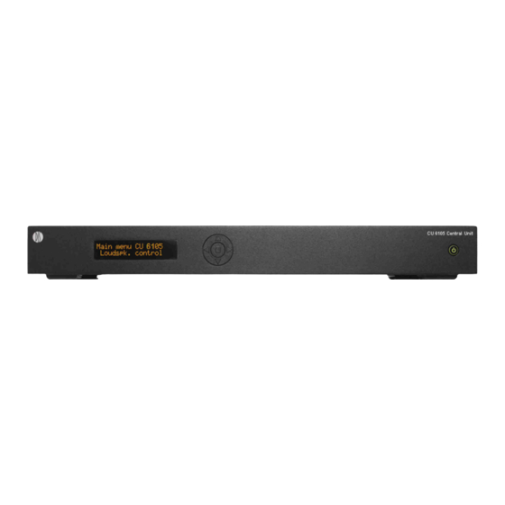
User Manual CU 6110 Central Unit Overview The CU 6110 Central Unit for the DCS 6000 is the 1. Menu display – A 2x20 character OLED- heart of the system. One CU 6110 is needed in display is used as an interactive display for each DCS 6000 system. -
Page 15: Simplified Audio Schematic
DCS 6000 Digital Conference System User Manual 3. LAN (TCP/IP) connector – A RJ45 connector ‘In 2’ is also used for connection of an for connection to local area network (LAN). ‘Emergency Evacuation Message (EEM)’ This connector is used to connection to the audio signal. -
Page 16: Connecting Units
When using JB 6104 Junction boxes, the Please refer to the ‘User Manual JB 6104’ for conference units can be connected and further details. disconnected without interrupting the conference. Figure 0-B Connecting DCS 6000 conference units using JB 6104 Junction Boxes. -
Page 17: Connecting A Pc
Opening the browser in the PC or on the iPad gives the option of configuring the system and Figure 0-D Connecting the DCS 6000 Digital Conference System to a PC and an iPad Connecting an audio recorder... -
Page 18: Connecting An Audio Mixer
Figure 0-E Connecting the DCS 6000 Digital Conference System to an audio recorder. Connecting an audio mixer The CU 6110 is connected to the Conference Units Use the ‘Group’ selection for the eight outputs using EC 6001-xx Cat5e cables. -
Page 19: Connecting Interpretation Units
All four the DCS-LAN chain connectors on the CU 6110 can be used for connecting the Conference Audio from the Interpreter Units can then be Units. heard in the headphones connected to the Chairman and Delegate Units. Figure 0-G DCS 6000 Digital Conference System with interpretation functionality. -
Page 20: Using Wireless Language Distribution
‘Floor’ Units can then be heard in the headphones and the interpreter channels. Refer to section ‘Web Browser Setup and Control’’ item #8. Figure 0-H DCS 6000 Digital Conference System with interpretation and wireless distribution, Floor, Ch.1 to Ch.7... -
Page 21: Using Rp 6004 Repeater
680m. Figure 0-I DCS 6000 Digital Conference System with RP 6004 Repeater. Using PS 6001 DCS-LAN Power Kit The PS 6001 is a kit consisting of a PS CU Power Supply and a PI 6000 Power Inserted. The kit can be inserted in the DCS-LAN chains at any point, where additional power is needed. -
Page 22: Connecting To Sw 6000
Chairman or a Technician. Please refer to the SW 6000 User Manuals for more information. Figure 0-K DCS 6000 Digital Conference System with basic SW 6000 setup Figure 0-L DCS 6000 Digital Conference System with advanced SW 6000 setup... -
Page 23: Connecting An Emergency Signal
DCS 6000 Digital Conference System User Manual Connecting an emergency signal To use the emergency signal function, a switch distributed to all output channels, overriding all (normally-open) must be connected to the other audio inputs. emergency switch connector. When the switch is Important: The level of the signal must be closed an “Emergency Evacuation Message (EEM)”... -
Page 24: Web Browser Setup And Control
DCS 6000 Digital Conference System User Manual Web Browser Setup and Control Important: The ‘CU 6110 Web Browser Control’ has CU 6110 Setup (browser) been tested with the following browsers: All configurations and operation options of the CU IE8/9+, Firefox 10+, Safari and Chrome 6110 can be set using a web browser in a PC, Other browsers might work but have not been tested. - Page 25 DCS 6000 Digital Conference System User Manual Menu Settings Description Unit Count – Shows the number of connected units on each chain. Unit Status – Shows the connected Conference units with Serial Number and Type of units. The ‘State’ field shows if a unit is ‘Active’...
- Page 26 DCS 6000 Digital Conference System User Manual Menu Settings Description CU hostname – A host name can be assigned to the CU 6110. This name can be used to connect to the CU 6110 with a browser instead of using the IP- address.
- Page 27 DCS 6000 Digital Conference System User Manual Menu Settings Description Language – Selecting the browser interface language. English language is default. Interpretation Setup – Used to set the number of Interpreter Channels in use (0 to 31). When set to value ‘0’ no interpretation channels are present in the system.
- Page 28 DCS 6000 Digital Conference System User Manual Menu Settings Description Language setup – The “Language setup” menu shows the number of channels according to the ‘Interpreter Channels’ settings. The language for each channel can be selected used the drop down list.
- Page 29 DCS 6000 Digital Conference System User Manual Menu Settings Description Auto Floor – When set to ON a language channel with no interpretation will have the Floor sound. Interpreter Lock – The Interlock settings are used to setup the interlock between the Interpretation channels.
- Page 30 DCS 6000 Digital Conference System User Manual Menu Settings Description Delegate Setup - All units connected are shown in this list with a ‘Seat Number’ and a ‘Delegate name’. When a unit is connected for the first time, it will be assigned the next ‘Seat...
- Page 31 DCS 6000 Digital Conference System User Manual Menu Settings Description Unit to Seat Relation – All units connected are shown in this list with ‘Serial Number’ and ‘Seat Number’. When a unit is connected for the first time, it will be assigned the next available ‘Seat Number’...
- Page 32 DCS 6000 Digital Conference System User Manual Menu Settings Description Activating the ‘Arrow Down’ button in the right upper corner reveals a window with options to change settings for a range of seats. Reset to Factory Defaults – When the reset button is...
- Page 33 DCS 6000 Digital Conference System User Manual Menu Settings Description Input Control – The Gain of ‘Audio In 1 & 2’ can be set to ‘0 dB’ or ‘10 dB’. When set to ‘10 dB’ the input signal is amplified 10 db.
- Page 34 DCS 6000 Digital Conference System User Manual Menu Settings Description Audio Output – The ‘Source’ can be selected for each of the eight outputs (the graphics is only showing four of the eight outputs). The choices using the dropdown menu are:...
- Page 35 DCS 6000 Digital Conference System User Manual Menu Settings Description Group Setup – The Conference units can be assigned individually to eight groups (the graphics is only showing four of the eight groups). ‘Group A’ is always used as the source to the built-in loudspeakers.
- Page 36 DCS 6000 Digital Conference System User Manual Menu Settings Description Ambient Microphone – Used to enable/disable a connected AM 6040 Ambient Microphone Unit. When ‘enabled’, the Ambient Noise Microphone is active. When ‘Audio In 1 or 2’ is routed to ‘Loudspeaker’’ and ‘Audio In Volume’...
- Page 37 DCS 6000 Digital Conference System User Manual Menu Settings Description Delegate Setup – The number of ‘Max speakers: Total’ defines the maximum number of participants, which can speak at the same time. This includes both delegate and chairman units. The number of ‘Max speakers: Delegates’...
- Page 38 ‘unwanted’ noise will only make the microphone to open a few seconds. “Last Mic Stays Open” feature is used when the DCS 6000 system is used for video or audio conferences where equipment with echo- canceling feature is in use.
- Page 39 DCS 6000 Digital Conference System User Manual Menu Settings Description Report – If a report is needed for factory diagnostic purposes. The report can be printed using an installed printer on the PC or saved to a html file. Figure 0-B...
-
Page 40: Cu 6110 Mic. Control (Browser)
DCS 6000 Digital Conference System User Manual CU 6110 Mic. Control (browser) The microphone control screen is selected by clicking the ‘Microphone Control’ button in the ‘CU 6110 Setup’ screen. Figure 0-D shows the screens available with a description of the functionality for each screen. - Page 41 DCS 6000 Digital Conference System User Manual Screen Description Speakers – Shows the list of active speakers. The number of list lines are defined by the setting in ‘Max. Total Speakers’. A speaker is turned off by clicking the speaker name.
-
Page 42: Using Web Browser In Pc
DCS 6000 Digital Conference System User Manual Using Web browser in PC Opening the ‘CU 6110 Setup’ in one window and the ‘CU 6110 Microphone Control’ in another window or tab makes it easy to switch between the two screens. To get Full Screen mode press F11. -
Page 43: Operation Modes
‘Speak’ button. Most DCS 6000 conference units have a Note: Manual mode is normally never selected/used ‘Function’ button, which as default is configured on CU 6110 if a Browser, AMX ®, Crestron ® or with ‘Mute’... -
Page 44: Delegate Interrupt Mode
DCS 6000 Digital Conference System User Manual ‘Manual + Reply’ mode be opened. Pressing the microphone buttons will not turn on the microphone but 3 The delegate enters into the ‘Reply List’ by flashes in the green LED will indicate, that pressing the Reply button on his user interface. -
Page 45: Troubleshooting
DCS 6000 Digital Conference System User Manual Troubleshooting In this chapter a simple fault-finding guide is given. This is intended to be used to remedy the consequences of incorrect installation. If more serious faults or problems arise the installer should contact a qualified technician. - Page 46 DCS 6000 Digital Conference System User Manual The CU 6110 browser application Check the IP address using the interactive menu on the CU: will not open in a PC or iPad ‘LAN setup/IP address setup/IP address’. Use this IP address in...
-
Page 47: Firmware Update
DCS 6000 Digital Conference System User Manual Firmware Update If firmware update of the CU 6110 Central Unit is needed for maintenance, this is done using the browser interface. Type the ‘IP address’ or ‘Host Name’ followed by ‘/cgi-bin/update.cgi’ into the browser as shown in Figure 0-A. - Page 48 DCS 6000 Digital Conference System User Manual Figure 0-C Update is finalized...
-
Page 49: Technical Specifications
DCS 6000 Digital Conference System User Manual Technical Specifications System Specification Overall system characteristics Temperature range The microphone system conforms to IEC 60914, the To guarantee specified performance ... 5 Deg C. to 40 international standard for Conference systems. Deg C. -
Page 50: Connection Details
DCS-LAN Chain Pair 4: Pin 7 & 8 The DCS 6000 system uses shielded Cat5e, Cat6 The phase of the pairs must be correct and the or Cat7 F/UTP or U/FTP cables with shielded RJ45 wiring spec. as stated in Cat5e (EIA 568-B) connectors. -
Page 51: Accessories
DCS 6000 Digital Conference System User Manual Connect the emergency switch to pin 1 and 2. Accessories Gooseneck Microphones Headphones GM 6523 ....Gooseneck Microphone, 40 cm DH 6021 ......Stereo headphones GM 6524 ..... Gooseneck Microphone, 50 cm Expansion units GM 6525 ..... -
Page 52: External Control Protocol
If the CU 6110 is assigned IP address supplementing the control functionality available 192.168.1.100, the external application must through the DCS 6000 Browser interface and the connect the TCP/IP socket to the address CU 6110 interactive display, however some 192.168.1.100:3142. -
Page 53: Cmd Structure (External To Cu 6110)
DCS 6000 Digital Conference System User Manual Cmd structure (External to CU 6110) To control the CU an External Control sends commands to CU 6110 included in command lines. Commands lines are build up in a very simple manner: <command><SP><data><CR>... -
Page 54: Retrieving System Status
DCS 6000 Digital Conference System User Manual -Speak list is already full (‘max_speakers’), and delegate interrupt is not ‘on’. Retrieving system status The CU supports streaming of status. When an External Control issues a ‘mic_status’, ‘audio_status’, ‘reply_status’ or ‘voting_status’ command, the CU responds by sending the status. Hereby, it is possible for an External Control to synchronize with the CU status. - Page 55 DCS 6000 Digital Conference System User Manual 5-button voting sessions the following alternatives apply: ‘+ +’ ‘+’ ‘0’ ‘-‘ ‘- -‘ Example: Voting Assume, that the CU 6110 is not controlled by SW 6000 ExtCtrl ----------------------------------> voting_status ----------------------------------> <---------------------------------- voting_configuration 1 3-button voting...
-
Page 56: Microphone Control
DCS 6000 Digital Conference System User Manual Microphone Control External Commands to CU 6110 Turn on microphone mic_on <seat no><CR> Instruct the CU to turn on microphone at seat_no. If the CU turns on the microphone, it will reply with a ‘mic_on’ command. And, if the microphone appeared in the request list, it is taken out of the request list, which makes the CU issue a ‘mic_request_off’... - Page 57 DCS 6000 Digital Conference System User Manual Turn on microphone from request list mic_on_from_request xCR> Turns on microphone x from the request list. If a microphone is turned on, the CU sends a ‘mic_on’ command and a ‘mic_request_off’ command. Place microphone in request list mic_request_on <seat no><CR>...
- Page 58 DCS 6000 Digital Conference System User Manual Set max replies max_replies <max replies><CR> Maximum number of delegates allowed in the reply list. <max replies> Can be set to “0” to “250”. The CU responds by sending a 'max_replies’ command. Set max requests max_requests <max requests><CR>...
- Page 59 DCS 6000 Digital Conference System User Manual The CU responds by sending microphone system status. The status is a list of commands from the CU: mic_status (for all units in the system) seat_state (for all units in the system) mic_priority...
-
Page 60: Cu 6110 Commands To External
DCS 6000 Digital Conference System User Manual CU 6110 Commands to External Microphone on mic_on <seat no> <name> <CR> A microphone is turned on. <seat no>: The seat number <name>: The seat name or delegate name. The seat name is name that can be edited by the web interface when the CU is standalone. - Page 61 DCS 6000 Digital Conference System User Manual Microphone off mic_off <seat no><CR> A microphone is turned off. Microphone in reply list mic_reply_on <seat no> <reply position> <reply #> <name> <CR> A microphone is inserted into reply list. <seat no>: The seat number <reply position>...
- Page 62 DCS 6000 Digital Conference System User Manual Max delegate speakers max_speakers <max speakers><CR> Maximum number of delegates allowed to speak. <max speakers> "1" to "8" Max replies max_replies <max replies><CR> Maximum number of delegates allowed in the reply list. <max replies> "0" to "250".
-
Page 63: Audio Control
DCS 6000 Digital Conference System User Manual • When the external control application requests microphone status (mic_status). • When a microphone unit becomes lost or found <seat number> The seat number identification of a microphone unit. An integer ranging from 1 to 65535. - Page 64 DCS 6000 Digital Conference System User Manual Set line input 2 level line_input_level_2 <level><CR> Adjust the level of line input signal. <level> The level of line input 2 ranges from -41 to 0. The value -41 indicates Off, whereas values from -40 to 0 indicates attenuation in dB.
-
Page 65: Commands From Cu 6110 To External
DCS 6000 Digital Conference System User Manual The CU responds to this command by returning an ‘audio_path’ command. Set Individual Speaker Attenuation This command is only available on CU 6110 mic_speaker_attenuation <seat_number> <Attenuation><CR> This command sets the speaker attenuation of a microphone. - Page 66 DCS 6000 Digital Conference System User Manual Level of line input 1 signal. <level> The level of line input 1 ranges from -41 to 0. The value -41 indicates Off, whereas values from -40 to 0 indicates attenuation in dB.
-
Page 67: Voting Control
DCS 6000 Digital Conference System User Manual Individual Speaker Attenuation mic_speaker_attenuation <seat_number> <Attenuation><CR> Indicates the speaker attenuation of a microphone. Only available on CU 6110. <seat_number> The microphone that has been adjusted <Attenuation>: The desired speaker attenuation. Possible values: 0 to 7. -
Page 68: Cu 6110 Commands To External
DCS 6000 Digital Conference System User Manual Cancel a voting session cancel_voting<CR> Used to cancel an ongoing voting session in the CU. If the voting session is cancelled, the CU replies with ‘voting_cancelled’. Start attendance check session start_attendance_check<CR> Used to start an attendance check session in the CU. If an attendance check session is started, the CU replies with ‘attendance_check_started’. - Page 69 DCS 6000 Digital Conference System User Manual <result_id> With SW 6000 connected values [1 to 9] corresponding to the 9 result columns in the SW 6000 ‘Voting Configurations’. For a standalone CU 6105 this is the button numbers [1 to 5].
- Page 70 DCS 6000 Digital Conference System User Manual Voting Status complete voting_status_done<CR> Informs that voting status streaming is complete.
- Page 71 United States, Canada, Latin Europe, Middle East, Africa: Asia, Pacific: America, Caribbean: Shure Incorporated Shure Europe Gmbh Shure Asia Limited 22/F, 625 King's Road 5800 West Touhy Avenue Jakob-Dieffenbacher-Str. 12 North Point, Island East, 75031 Eppingen Niles, IL 60714-4608 Hong Kong...
Need help?
Do you have a question about the DCS 6000 and is the answer not in the manual?
Questions and answers