Table of Contents
Advertisement
S
HAPESHIFTER
User Manual
© Barco Lighting Systems, 2014, All Rights Reserved
Information and specifications in this document are subject to change without notice. Barco Lighting Systems
assumes no responsibility or liability for any errors or inaccuracies that may appear in this manual.
Trademarks used in this text:
High End Systems, Wholehog, and Lithopatterns are registered trademarks: and intellaspot, Internal Effects, the
High End Systems globe logo, and the Hog logo are trademarks of Barco Lighting Systems, High End Systems,
Inc. is a registered trademark. Belden is a registered trademark of Belden, Inc.
Other trademarks and trade names may be used in this document to refer to either the entities claiming the
marks and names or their products. High End Systems disclaims any proprietary interest in trademarks and
trade names owned by others.
SHAPESHIFTER User Manual
Version 1.2
June, 2014
Advertisement
Table of Contents
Troubleshooting

Related Manuals for High End Systems Shapeshifter C1


Summary of Contents for High End Systems Shapeshifter C1
- Page 1 High End Systems, Wholehog, and Lithopatterns are registered trademarks: and intellaspot, Internal Effects, the High End Systems globe logo, and the Hog logo are trademarks of Barco Lighting Systems, High End Systems, Inc. is a registered trademark. Belden is a registered trademark of Belden, Inc.
- Page 2 Contact Information U.S. and the Americas Sales Department High End Systems 2105 Gracy Farms Lane Austin, TX 78758 USA voice: 512.836.2242 fax: 512.837.5290 Toll Free: 800.890.8989 Customer Service High End Systems 2105 Gracy Farms Lane Austin, TX 78758 USA voice: 800.890.8989 fax: 512.834.9195...
-
Page 3: Shapeshifter User Manual
Umständen gegen die diesbezüglichen Sicherheitsnormen verstoßen. Avvertenza Sulla Modifica Del Prodotto I prodotti di High End Systems sono stati progettati e fabbricati per soddisfare i requisiti delle normative di sicurezza statunitensi ed internazionali. Qualsiasi modifica al prodotto potrebbe pregiudicare la sicurezza e rendere il prodotto non conforme agli standard di sicurezza pertinenti. -
Page 4: Important Safety Information
Important Safety Information Instructions pertaining to continued protection against fire, electric shock, and injury to persons are found throughout this manual. Please read all instructions prior to assembling, mounting, and operating this equipment. The following international caution and warning symbols appear in margins throughout this manual to highlight messages. -
Page 5: Warranty Information
A fixture must be returned in its original packaging. Any other parts returned to High End Systems must be packaged in a suitable manner to ensure the protection of such product unit or parts, and such package shall be clearly and prominently marked to indicate that the package contains returned Product units or parts and with an RMA number. -
Page 6: Patents
Patents This product may use one or more of the following patents: US 4,392,187; US 4,602,321; US 4,688,161; US 4,701,833; US 4,709,311; US 4,779,176; US 4,800,474; US 4,962,687; US 4,972,306; US 4,980,806; US 5,010,459; US 5,031,078; US 5,073,847; US 5,078,039; US 5,186,536; US 5,209,560; US 5,278,742; US 5,282,121;... -
Page 7: Table Of Contents
Returning an Item Under Warranty for Repair ..........v Freight ..................... v Patents ...................... vi Chapter 1: Product Overview This chapter describes the features and specifications of the SHAPESHIFTER C1 and SHAPESHIFTER W1 fixtures along with a list of related products and accessories. Features ...................... 1 Operation .................... - Page 8 Linking SHAPESHIFTER Fixtures ..............9 Cable Connectors ..................9 Connecting to the Link ................10 Terminating the Link .................. 11 Configuring SHAPESHIFTER for DMX Control ..........12 Setting a Start Channel in Battery Mode ............12 Powering On the Fixture ................13 Shutting Down the Fixture .................
- Page 9 Programming with a DMX Console ..............35 SHAPESHIFTER DMX Protocol Options ............36 Reduced Protocol Mode ................36 SHAPESHIFTER C1 Reduced Protocol ............36 SHAPESHIFTER W1 Reduced Protocol............36 Enhanced Protocol Mode ................37 SHAPESHIFTER C1 Enhanced Protocol ............37 SHAPESHIFTER W1 .................
- Page 10 Parameter Descriptions ................39 Positioning Parameters ................39 Fixture Pan and Tilt ................. 39 Module X and Y Position ................39 Color Parameters ..................40 Shutter Parameters ................... 41 Shutter Function ..................41 Shutter ....................41 Dim ....................... 41 MSpeed (Motor Speed) ................41 Macros .....................
-
Page 11: Chapter 1: Product Overview
With technology that combines the output of 126 high-powered LEDs with custom lensing, SHAPESHIFTER is the brightest LED fixture in the industry. Two versions- SHAPESHIFTER C1 (RGB) and SHAPESHIFTER W1 (White) are available, with the C1 outputting 24,000 RGB lumens and the W1 an incredible 27,000 lumens. -
Page 12: Operation
CHAPTER 1 Product Overview Operation • Auto-switching power supply • 100v-240v • DMX/RDM Connector: 5-pin and 3-pin XLR Specifications Mechanical Specifications Fixture Dimensions: 388mm x 320mm x 520mm (15.3in x 12.6in x 20.5in) Roadcase Dimensions: 660mm x 540mm x 905mm (25.98in x 21.25in x 35.62in) Fixture Weight: 26.9 kg (59.3 lbs) Shipping Weight: 61 kg (134.5 lb) SHAPESHIFTER User Manual... -
Page 13: Electrical Specifications
CHAPTER 1 Product Overview Electrical Specifications Fixture Rated Power: 700 W Power consumption: 100V 50 7 amps 120V 60 6 amps 240V 50/60 3 amps Warning: Class I equipment - For continued protection against electric shock connect this equipment to an earthed (grounded) power source only. -
Page 14: Fixture Components
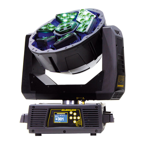
CHAPTER 1 Product Overview Fixture Components 1. Lens 2. Microphone 3. DC Switch 4. Display 5. Right-button 6. Up-button 7. ENTER-button 8. Left-button 9. Mode/Esc-button 10. Down-button 11. Handle 12. 5-pin DMX out 13. 5-pin DMX in 14. 3-pin DMX out 15. -
Page 15: Chapter 2: Shapeshiftersetup And Configuration
Return a ® product for repair in its original packaging. Before sending anything to the factory, call your High End Systems dealer/distributor for a Return Material Authorization (RMA) number. The factory cannot accept any goods shipped without an RMA number. -
Page 16: Installing A Power Cord Cap
Because of the variety of power cord caps used worldwide, High End Systems, Inc. cannot make specific recommendations for the power cord cap. Contact a local authority for the type of power cord cap needed. -
Page 17: Mounting The Fixture
Always use a secondary safety cable when mounting this fixture. Do not mount within .5 meters (1.6 feet) of a flammable object. Note: Due to the wide variety of possible lighting designs, High End Systems cannot make specific mounting recommendations. Consider the following procedures as suggested guidelines only. - Page 18 Failure to use a safety cable could result in injury or death. High End Systems supplies the proper safety cables and may be contacted for replacements if necessary.
-
Page 19: Linking Shapeshifter Fixtures
CHAPTER 2 SHAPESHIFTER Setup and Configuration Linking SHAPESHIFTER Fixtures The SHAPESHIFTER fixture operates on standard DMX512 link controlled by a DMX console. The number of fixtures on a link will be determined by the combined number of channels required by all the fixtures. -
Page 20: Connecting To The Link
CHAPTER 2 SHAPESHIFTER Setup and Configuration Test each cable with a voltage/ohm meter (VOM) to verify correct polarity and to make sure that the negative and positive pins are not grounded or shorted to the shield or to each other. CAUTION! Do not connect anything to the ground lug on the XLR connectors. -
Page 21: Terminating The Link
CHAPTER 2 SHAPESHIFTER Setup and Configuration Terminating the Link Terminate the link by installing a 120 ohm, 1/4 watt (minimum) terminator in the fixture’s Data Out (female) cable connector in the last fixture on each DMX link. To construct a terminator: 1. -
Page 22: Configuring Shapeshifter For Dmx Control
CHAPTER 2 SHAPESHIFTER Setup and Configuration Configuring SHAPESHIFTER for DMX Control Each SHAPESHIFTER fixture requires a block of 28 channels (Reduced protocol) or 79 channels (Expanded protocol) on a standard DMX512 link. For more information on Start Channels, see Determining DMX Start Channel Assignment on page 21. Address your fixture by setting the first channel of the channel range you want to assign this fixture on the link. -
Page 23: Powering On The Fixture
CHAPTER 2 SHAPESHIFTER Setup and Configuration Powering On the Fixture WARNING: This equipment is designed for connection to a branch circuit having a maximum overload protection of 20 A. CAUTION: Do not power on the fixture until verifying that the line cord cap is suitable for the power source in your location. - Page 24 CHAPTER 2 SHAPESHIFTER Setup and Configuration SHAPESHIFTER User Manual...
-
Page 25: Chapter 3: Menu System
Chapter 3: Menu System This chapter shows you how to access and navigate the onboard Menu system and the options available for each menu with examples. Menu System Overview The front panel on SHAPESHIFTER fixtures has a full color LCD screen and navigation buttons to display and operate the onboard menu system. -
Page 26: Navigation Basics
CHAPTER 3 Menu System Navigation Basics 1. Enter the Menu system by pressing the Mode/Esc MODE button for a few seconds until the / ESC menu appears. 2. The current option is displayed. Use the buttons to scroll through menu options at the current level. -
Page 27: Shapeshifter Menu Map
CHAPTER 3 Menu System SHAPESHIFTER Menu Map Menu Level 2 Level 3 Option/Setting Description/Notes Sets the first value of a unique Address Set DMX: ### 1‐484 channel range on DMX link. Power On running time in hours Current Time ####h Fixture running time in hours Ttl Life Hrs ####h Clears last Run Hours Time... - Page 28 CHAPTER 3 Menu System Menu Level 2 Level 3 Option/Setting Description/Notes Turns fan off and on depending Auto on temperature Note: HI and LOW settings not Runs fan at high speed available in all software versions. Runds fan at low speed Time until auto shutoff in minutes Shutoff Time 02m‐60m...
- Page 29 CHAPTER 3 Menu System Menu Level 2 Level 3 Option/Setting Description/Notes Reverts to playback via console DMX Control Slave 1 Assigns slave setting Set to Slave Slave 2 Slave 3 Playback Master Assigns auto program mode Auto Program Alone Master Assigns music control mode Music Control Alone Program 1 Prog.Part 1 ...
-
Page 30: Menu System Options
CHAPTER 3 Menu System Menu System Options The following sections describe and give examples for selecting and/or setting available fixture configuration options. Address Menu Address is the top level menu selection used to set the fixture’s DMX start channel. You can address the fixture before applying power in the battery mode or in normal mode after you power up the fixture. -
Page 31: Determining Dmx Start Channel Assignment
Channel Start Notes Type Range Position Footprint Channel The Start channel is the first channel SHAPESHIFTER C1 First 28 channels C001 1-28 in a consecutive block of channels (Reduced Protocol) assigned to a fixture. Fixture can be assigned the second... -
Page 32: Information Menu
CHAPTER 3 Menu System Information Menu The Information menu displays current fixture information such as internal temperature, total fixture hours, software version, and DMX values for each of the fixture’s parameters. Fixture hours resets are executed in the Information Menu. To enter the Information Menu: 1. -
Page 33: Values Display
CHAPTER 3 Menu System Values Display This menu option lets you view the current DMX value for each of the fixture’s parameters. To view DMX values by Parameter: 1. Navigate to and select the Info menu as shown on page 22. 2. -
Page 34: Set Menu
CHAPTER 3 Menu System Set Menu The Set Parameters menu lets you configure your fixture’s motion, display, and data source settings. To enter the Set menu: 1. Press the MODE/ESC button to enter the first level of the menu system. The display will MODE / ESC show Address and Info as the first two options in the top menu level. -
Page 35: Service Setting
CHAPTER 3 Menu System Pan Degree The standard pan range of a SHAPESHIFTER fixture is 0–540°. This option lets you expand the pan range to an upper limit of 630°. To expand the pan range, scroll from the default option of 540 to 630 and press the button to select. -
Page 36: Display Setting
CHAPTER 3 Menu System Display Setting This Set option lets you control how the display functions. To select the Display Setting menu 1. Navigate to and select the Set menu as shown on page 24. 2. Using the buttons, scroll to Display Setting and press the button to select. -
Page 37: Test Options Menu
CHAPTER 3 Menu System Test Options Menu This menu lets you manually Home the fixture and change DMX values for parameters. To Enter the Test Options Menu: 1. Press the MODE/ESC button to enter the first level of the menu system. The display will MODE / ESC show Address and Info as the first two options in the top menu level. -
Page 38: Calibration
CHAPTER 3 Menu System Calibration This Test menu option lets you fine tune the home position for Pan and Tilt motors. To calibrate Pan after homing: 1. Navigate to and select the Test menu as shown above. 2. Using the buttons, scroll to Calibration and press the button to select. -
Page 39: Preset Programming Overview
CHAPTER 4 Preset Programming Chapter 4: Preset Programming SHAPESHIFTER fixtures can be programmed through the onboard menu system using Preset Programming. This section describes how to program your fixtures for stand-alone operation using the on-board memory in each fixture to create and store scenes. Preset Programming Overview Presets are built from combining scenes into programs and then assigning the programs to Program Partitions for playback by a fixture designated as the Master and, if desired, groups of... -
Page 40: Master And Slave
CHAPTER 4 Preset Programming Master and Slave The following example shows the relationship between scenes, programs and partitions programmed on the Master and how slave groups are assigned. • Groups of scenes are edited into Programs 1– 6 on the fixture designated as Master •... -
Page 41: Preset Menu
CHAPTER 4 Preset Programming Preset Menu Playback Settings Preset programming requires one fixture to act as the Master. All other SHAPESHIFTER fixtures on the link can then be set as slaves to playback the Master presets. Slave fixtures receive all their preset parameter and timing information from the master fixture. -
Page 42: Edit Scenes
CHAPTER 4 Preset Programming Edit Scenes A parameter is a fixture attribute that can be controlled to modify the light beam in terms of color, beam quality and pattern, intensity, or focus (position). DMX programming assigns a DMX value to each of the fixture’s parameters. -
Page 43: Set Input By Out
CHAPTER 4 Preset Programming Set Input by Out This Scene Edit option allows you to capture the parameter values for a scene from DMX input into the fixture. Once you create a look from a DMX console do the following: 1. -
Page 44: Select Program
CHAPTER 4 Preset Programming Select Program This preset option lets you assign a Preset Program to one of three Program Partitions. A fixture assigned as a Slave can playback any Program Partition defined by the Master fixture. Note: The Master fixture can only playback Program Partition 1 To assign a program to each Program Partition: 1. -
Page 45: Chapter 5: Dmx Programming
4, Full Boar 4, and Hedge Hog lighting consoles; and Hog 4PC software are available from High End Systems to control SHAPESHIFTER fixtures (see Related Products and Accessories on page 5). For information on whether your DMX controller supports SHAPESHIFTER fixtures, contact the controller’s vendor. -
Page 46: Shapeshifter Dmx Protocol Options
DMX Programming SHAPESHIFTER DMX Protocol Options Both SHAPESHIFTER C1 and M1 models have Reduced and Enhanced protocol options. The Reduced Protocol option uses 28 channels of a standard DMX512 link to control Position, Color mixing, Module movement, Macros, Dimming, Shutter, MSpeed, and the Indigo Highlighter system. -
Page 47: Enhanced Protocol Mode
CHAPTER 5 DMX Programming Enhanced Protocol Mode SHAPESHIFTER C1 Enhanced Protocol Chan Function Chan Function Chan Function LED1 Green LED4 Function LED1 Blue LED4 Dim LED1 Function Tilt LED5 X LED1 Dim Master LED Function LED5 Y LED X LED2 X... -
Page 48: Shapeshifter W1
CHAPTER 5 DMX Programming SHAPESHIFTER W1 Chan Function Chan Function Chan Function LED1 White 2 LED4 Function LED1 White 3 LED4 Dim LED1 Function Tilt LED5 X LED1 Dim Master LED X/Y Function LED5 Y LED5 White 1 LED X LED2 X LED y LED2 Y... -
Page 49: Parameter Descriptions
CHAPTER 5 DMX Programming Parameter Descriptions Individual parameters are described in the following sections. Note: All DMX values indicated in the detailed parameter descriptions are in decimal units. Positioning Parameters Fixture Pan and Tilt The SHAPESHIFTER fixture has a 630° pan range and a 270° tilt range. Two DMX channels provide 16-bit adjustment to a fraction of a degree for pan and tilt position. -
Page 50: Color Parameters
DMX Programming Color Parameters Each Module of a SHAPSHIFTER fixture is composed of three groups of LEDs. In SHAPESHIFTER C1 fixtures, these are colored LEDs. When they are all set at the same intensity level, they project as white. In SHAPESHIFTER W1 fixtures, the LEDs are still grouped but are all white. -
Page 51: Shutter Parameters
CHAPTER 5 DMX Programming Shutter Parameters Shutter Function The Shutter Function parameter control normal shutter and strobing features. Shutter Options Description Value Normal Shutter Functions 0-23 Opens and closes shutter flags in the optical path Random Random Strobe 24-299 Strobes beam at random intervals Synchronizes random strobing for all SHAPESHIFTER fixtures using Synchronous Random Strobe 230-255 the same DMX controller... -
Page 52: Macros
CHAPTER 5 DMX Programming Macros SHAPESHIFTER fixtures provides factory programmed multi-step macros to create a variety of looks without extensive user programming. Three Macro types give you varying levels of control over the look. Note: Inclusive Macros and Intensity Macros are designed to work with the fixture in RGB mode on the Mix Color Function channel. -
Page 53: Control
CHAPTER 5 DMX Programming Control The Control parameter allows remote control of Display, Homing, Module Lamp and Shutdown. Note: To access all control settings, first select a control channel value, then set the Shutter channel to DMX = 0. Control Setting Description Value Safe... -
Page 54: Indigo Highlighter
CHAPTER 5 DMX Programming Indigo Highlighter Indigo Highlighter system consists four 1-watt indigo LEDs that provide additional light output. Two parameters define the Indigo Highlighter operation. Indigo Highlighter Function You can choose to have the Indigo Highlighter system function independently from the fixture’s dimming or track it. -
Page 55: Chapter 6: General Maintenance And Troubleshooting
Chapter 6: General Maintenance and Troubleshooting This chapter outlines safety and maintenance procedures as well as troubleshooting error messages. Safety Considerations CAUTION: The information in this chapter is intended to assist qualified personnel only. Allow the fixture to cool before handling. WARNING: To avoid electrical shock, disconnect power before servicing. -
Page 56: Coplaner Alignment
CHAPTER 6 General Maintenance and Troubleshooting Coplaner Alignment Coplanar alignment allows the user to superimpose all seven beams and ensures that they all converge on the same area. The user adjusts each module after homing to be coplanar, selects coplanar alignment on the control channel, and these settings are stored into the fixture’s non- volatile memory. - Page 57 CHAPTER 6 General Maintenance and Troubleshooting For other lighting consoles use the following steps: 1. Set the fixture to Enhanced Mode in the menu system. Then, at the controller: 2. Set channel 5 [Master LED X/Y Function] to DMX value 255 3.
-
Page 58: Troubleshooting Error Messages
CHAPTER 6 General Maintenance and Troubleshooting Troubleshooting Error Messages When you turn on the fixture, it will make a reset at first. The display may show "Err channel is XX" while there are problems with one or more channels. "XX" stands for a channel with a testing sensor for positioning. -
Page 59: Led4 X Er
CHAPTER 6 General Maintenance and Troubleshooting LED4 X Er (LED4 X -error) This message will appear after the reset of the fixture if the magnetic-indexing circuit malfunction (sensor failed or magnet missing) or the stepping-motor is defective (or its driving IC on the main PCB). The LED4 X is not located in the default position after the reset. LED4 Y Er (LED4 Y - error) This message will appear after the reset of the fixture if the magnetic-indexing circuit malfunction (sensor failed or magnet missing) or the stepping-motor is defective (or its... - Page 60 CHAPTER 6 General Maintenance and Troubleshooting SHAPESHIFTER User Manual...
-
Page 61: Appendix A: Mspeed Conversion Table
Appendix A: MSpeed Conversion Table The following table lists the MSpeed (motor) movement times and their corresponding DMX controller values. If you have a numeric-type controller, use the Value Decimal (dec.) column. If you have a fader-type controller, use the Value Percentage (%) column. If your controller allows you to program hex values, use the Value (hex) column. - Page 62 Appendix A MSpeed Conversion Table Time Value Value Value Time Value Value Value Time Value Value Value (sec.) (dec.) (hex) (sec.) (dec.) (hex) (sec.) (dec.) (hex) 51.33 102.77 175.24 52.24 104.05 176.92 53.16 105.35 178.61 54.09 106.65 180.30 55.02 107.96 182.01 55.96v 109.28...
Need help?
Do you have a question about the Shapeshifter C1 and is the answer not in the manual?
Questions and answers