Table of Contents
Advertisement
User Manual
© High End Systems, Inc. 2001, All Rights Reserved
Information and specifications in this document are subject to change without notice.
High End Systems, Inc. assumes no responsibility or liability for any errors or
inaccuracies that may appear in this manual.
Trademarks used in this text: Lightwave Research, High End Systems, Studio Color,
Studio Spot, Technobeam, Intellabeam, Dataflash AF1000, WholeHog II, and
LithoPatterns are registered trademarks; and HandShake, x.Spot, TalkBack, Studio Spot,
Lithomotion, ZoomTrack, Internal Effects, Light Burst, Electronic Strobe, the High End
Systems globe logo and the Hog logo are trademarks of High End Systems, Inc. or High
End Systems Europe Ltd. Belden is a registered trademark of Belden, Inc. Philips is a
registered trademark of Philips Lighting Company. Fram is a registered trademark of
Allied Signal. ETL and C-ETL are registered trademarks of Intertek Testing Services.
Other trademarks and trade names may be used in this document to refer to either the
entities claiming the marks and names or their products. High End Systems disclaims any
proprietary interest in trademarks and trade names owned by others.
x.Spot™ User Manual
P/N 60600174 Version 2.0 September, 2001
Printed in the USA
S.G.
x.Spot ™ User Manual
i
Advertisement
Table of Contents
Troubleshooting

Related Manuals for High End Systems x.Spot


Summary of Contents for High End Systems x.Spot
-
Page 1: User Manual
Lithomotion, ZoomTrack, Internal Effects, Light Burst, Electronic Strobe, the High End Systems globe logo and the Hog logo are trademarks of High End Systems, Inc. or High End Systems Europe Ltd. Belden is a registered trademark of Belden, Inc. Philips is a registered trademark of Philips Lighting Company. - Page 2 Austin, TX 78758 USA voice: 800.890.8989 24-hour fax: 512.834.9195 24-hour voice mail: 512.837.3063 or 800.890.8989 U.S. New York High End Systems, Inc. New York 311 W. 43rd Street, Ste 400 New York, NY 10036 voice: 210.957.6840 fax: 212.957.4466 U.S. Los Angeles: High End Systems, Inc.
-
Page 3: Declaration Of Conformity
EN61000-4-2: 1995 Level 3, Cls2 EN61000-4-3: 1995 Level 2 EN61000-4-4: 1995 Level 2 EN61000-4-5: 1995 Level 2 EN61000-4-6: 1996 Level 2 EN61000-4-11: 1994 EN61000-3-2: 1995 Class A USA, Wednesday, October 03, 2001 Kenneth Stuart Hansen, Compliance Engineer x.Spot ™ User Manual... -
Page 4: Product Modification Warning
Sicherheitsnormen verstoßen. Avvertenza Sulla Modifica Del Prodotto I prodotti di High End Systems sono stati progettati e fabbricati per soddisfare i requisiti delle normative di sicurezza statunitensi ed internazionali. Qualsiasi modifica al prodotto potrebbe pregiudicare la sicurezza e rendere il prodotto non conforme agli standard di sicurezza pertinenti. -
Page 5: Important Safety Information
En el Apéndice C se encuentran instrucciones sobre protección continua contra incendios, descarga eléctrica, exposición excesiva a radiación ultravioleta (UV) y lesiones personales. Lea, por favor, todas las instrucciones antes del ensamblaje, montaje y operación de este equipo. x.Spot ™ User Manual... -
Page 6: Symbols
This symbol indicates an explosion hazard. This symbol indicates the minimum distance to a lighted object, which in this case, is 1 meter. This symbol indicates a hot surface. This symbol indicates that an object not be mounted on a flammable surface x.Spot™ User Manual... -
Page 7: Warranty Information
Lamps are covered by the lamp manufacturer’s warranty. Any Product unit or parts returned to High End Systems must be packaged in a suitable manner to ensure the protection of such Product unit or parts, and such package shall be clearly and prominently marked to indicate that the package contains returned Product units or parts and with an RMA number. - Page 8 User Manual...
-
Page 9: Table Of Contents
Table of Contents Contacting High End Systems® ....................ii Product Modification Warning ......................iv FCC Information ..........................iv Important Safety Information ......................v Symbols ............................vi Warranty Information........................vii Limited Warranty......................vii Returning an Item Under Warranty for Repair .............vii Freight..........................vii Table of Contents ........................... ix Table of Figures ........................xv... - Page 10 Setting the DMX Start Channel ....................2-11 Shutting Down the Fixture......................2-12 Chapter 3: Fixture Operation Direct x.Spot Menu System Access .................... 3-1 TalkBack™ Support for Remote Access ..................3-1 Navigating the Menu System ...................... 3-2 The x.Spot Display........................ 3-2 Navigational Basics.......................
- Page 11 Fixture Hours Reset ......................3-27 Lamp Hours ......................... 3-27 Lamp Strikes ........................3-27 Lamp HR/Strike Reset ......................3-27 Lamp Status......................... 3-28 Software Version......................... 3-28 Display Errors ........................3-28 Channels Needed ........................ 3-28 Next DMX Channel ......................3-28 x.Spot ™User Manual...
- Page 12 Chapter 4: DMX Programming x.Spot DMX Protocol........................4-1 DMX Programming Options ....................... 4-2 Show Creation with a DMX Controller ................4-2 Show Creation with Onboard Preset Menu ................ 4-2 Creating a Loop......................4-2 Playing Back a Loop ...................... 4-3 Synchronizing Preset Playback ..................4-3 DMX Parameter Descriptions .....................
- Page 13 Replacing a Dual Rotating Gobo Module in Slot 2............5-9 Replacing a Six-Wheel Color Mix Module for Slot 1 ..........5-10 Replacing Static Color Wheel Dichroic Wedges............... 5-11 Replacing x.Spot Lithopatterns® and Effects Glass ............5-12 Replacing Static Lithopatterns®................. 5-14 Cleaning the Glass Components ....................5-15...
- Page 14 ™User Manual...
- Page 15 Figure 3-1 Front panel display ....................3-2 Figure 3-2 x.Spot Menu System Overview ................3-5 Figure 3-3 Edit Scene Menu Options in Standard x.Spot ............3-9 Figure 3-4 Assigning timing to a scene .................. 3-12 Figure 3-5 Automatic Display Invert feature................. 3-18 Figure 4-1 Synchronized Playback Example ................
- Page 16 Table 3-2 Module Identification ....................3-20 Table 3-3 Self Test by Slot......................3-24 Table 4-1 Parameters for a Standard Configuration x.Spot Fixture ........4-1 Table 4-2 Lamp Control and Shutter Parameter Settings............4-5 Table 4-3 Frost Setting Descriptions ..................4-7 Table 4-4 Control Setting Descriptions ...................
-
Page 17: Chapter 1: Features And Specifications
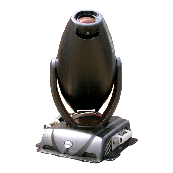
Chapter 1: Features and Specifications The x.Spot ™ luminaire integrates multiple advances in automated lighting technology to give the lighting designer the ultimate hard-edge fixture for professional applications. The modular design shown in Figure 1-1 includes three user-configurable slots to allow maximum customization and upgradability. -
Page 18: X.spot™ Features
In the standard x.Spot configuration, the wheels of the modules in Slots 2 and 3 interleave to allow for the maximum range of effects. Figure 1-2 Module Interleaving in Standard x.Spot™ fixture Slot 3 Slot 2 Rotating Gobo and Iris... -
Page 19: Construction
— Moire and overlay effects capability on two positions of Gobo wheel 1 Rotating Gobo and Iris Module ® • Gobo wheel 2 has seven rotating, indexing Lithopatterns glass gobos with stacking capability (plus open) • Variable Iris x.Spot ™ User Manual Features and Specifications... -
Page 20: Optional Accessories
For more information about optional accessories, contact either your High End Systems dealer/distributor, High End System Sales, or visit the High End Systems Web site at www.highend.com. For additional contact information, see “Contacting High End Systems®” on page ii. -
Page 21: Specifications
(18.5in) 343mm (13.5in) 523mm 172mm (20.6in) 235mm (6.75in) (9.25in) 470mm 142mm (18.5in) (5.6in) 426mm 178mm (16.8in) (7.0in) 367mm (14.4in) 814mm (32.0in) 125mm (4.9in) 533mm (21in) 472mm 140mm (18.6in) (5.5in) 413mm (16.25in 557mm (21.9in) x.Spot ™ User Manual Features and Specifications... -
Page 22: Electrical Specifications
Image area: 31.75mm ± 0.25 mm (1.250in ± .010) • Maximum thickness: 3.81mm (.150 in) Lamp Specifications • Lamp type: Philips MSR700SA 700W short arc • Color temperature: 5600 K • Life: 500 hours Features and Specifications x.Spot™ User Manual... -
Page 23: Lens Specifications
• Maximum resistance: 20 /1000 ft. • Nominal impedance: 120 DMX data connectors: • 5-pin male and female XLR connectors DMX data terminators: • 5-pin male XLR connector with 120 ohm termination resistor x.Spot ™ User Manual Features and Specifications... - Page 24 Features and Specifications x.Spot™ User Manual...
-
Page 25: Chapter 2: Setup And Configuration
Setup and Configuration Unpacking the Fixture Unpack the x.Spot fixture and verify that it is undamaged. Inspect both the outside of the fixture for physical damage and the optical assembly for damage to glass components. To access the optical assembly, loosen the three (3) captive screws on each side of the fixture head. -
Page 26: Installing A Power Cord Cap
(even within the same country) may require a different power cord cap to connect the fixture to a power outlet. Because of the variety of power cord caps used worldwide, High End Systems, Inc. cannot make specific recommendations for the power cord cap. -
Page 27: Mounting The Fixture
32kg (70lbs) weight of the x.Spot fixture. If the surface is above floor height, use safety cables to secure the fixture to the surface . -
Page 28: Figure 2-3 Baseplate Configuration For Standard Truss Sizes
X.Spot fixtures are designed for 3- or 4-point installation on standard 12, 16 or 181/2 in. truss and are easily adapted for intelligent (retractable) truss mounting. Figure 2-3 shows some basic mounting options. Figure 2-3 Baseplate configuration for standard truss sizes 254.0mm... -
Page 29: Safety Cable
1. Disconnect power to the fixture. If it has been operating, allow the fixture to cool for five minutes before handling. 2. At least 2 people are required to mount the x.Spot fixture with one person on each side supporting and attaching that side of the fixture. Once the clamps are attached, one person can support the fixture while the other attaches safety cables. -
Page 30: Linking The Fixtures
Linking the Fixtures X.Spot fixtures can be linked to other fixtures on a standard DMX 512 link and then be controlled by the first fixture on the link or a DMX controller. The number of fixtures on a link will be determined by the combined number of channels required by all the fixtures. -
Page 31: Setting Up The Link
4. Connect a male terminator to the Data Out connector of the last fixture in the link (see “Constructing a Terminator” on page 2-8). For information on obtaining a terminator, see “Optional Accessories” on page 1-4. x.Spot ™ User Manual Setup and Configuration... -
Page 32: Constructing A Terminator
Purchase a terminator from a High End Systems dealer/distributor (see “Optional Accessories” on page 1-4), or follow the instructions below to construct a terminator. To construct a terminator: 1. -
Page 33: Powering On The Fixture
This equipment for connection to a branch circuit having a maximum overload protection of 20 A. The x.Spot fixture does not have a power switch. To power on the fixture, simply connect it to an appropriately-rated power source. Once connected, controller commands can remotely power up or shutdown the fixture (see Appendix A for DMX Tables). -
Page 34: Dmx Start Channel
2. Crossload software from one fixture that contains the new software to all other x.Spot fixtures on the link. See “Crossloading Fixture Software” on page 3-21. 3. Upload the new software to all x.Spot fixtures on the link using a HandShake™ handheld controller from High End Systems. -
Page 35: Setting The Dmx Start Channel
Use that range in calculating the Start channels on the link for those fixtures. Up to thirteen 38-channel standard x.Spot fixtures can be assigned to a single 512-Channel DMX link. For more information on Start Channels, see “Determining DMX Start Channel Assignment”... -
Page 36: Shutting Down The Fixture
Note: The last valid Start channel for an x.Spot fixture is based on the channel range required by fixture’s module configuration. The last valid start channel for a standard configuration x.Spot fixture is 475 (512–38+1). 5. Press the Enter button to accept the new DMX Start channel. The display will stop flashing when a new option is entered. -
Page 37: Chapter 3: Fixture Operation
TalkBack™ Support for Remote Access All x.Spot fixtures support TalkBack” technology. TalkBack™ technology is a new feature that allows remote access to the menu system built into High End Systems fixtures. A DMX controller supporting TalkBack protocol like the HandShake™... -
Page 38: Navigating The Menu System
Figure 3-1 shows the elements of the x.Spot display panel. The Menu system buttons on the x.Spot display panel control navigation. The Menu button is on the left. The Enter button is on the right. The center button navigates through the current menu level options [Left and Right] and values available for the current option [Up and Down]. -
Page 39: Navigational Basics
The software version loaded on the fixture can vary even between units purchased at the same time. “Verifying and Uploading Fixture Software” on page 2-10 describes the procedures to ensure that all x.Spot fixtures on the link are running the latest software. -
Page 40: Error Message Display
To exit the menu system, keep pressing the Menu button to back out of each menu level until the High End Systems logo appears. The word AUTOLOCK will appear briefly on the display to indicate the fixture’s software is “locking” the display. The display switches back to the large 8-character format and, after a few seconds, begins the standard display for the locked mode as described above. -
Page 41: Figure 3-2 X.spot Menu System Overview
Figure 3-2 x.Spot Menu System Overview DMX ADDRESS MENU SET DMX START CHANNEL ONBOARD PRESETS MENU SEND PRESETS TO PLAYBACK COPY SCENE CAPTURE DMX DEFAULT EDIT SCENE # OTHER FIXTURES MODE MENU MENU TO SCENE: ## PRESETS CHASSIS SLOT 1... -
Page 42: Dmx Address Menu
2. Use the up and down arrows on the Navigation button to select a new DMX start channel from 001– 498. The display will flash a new option ready for selection. Note: The last valid Start channel for an x.Spot fixture is based on the channel range required by fixture’s module configuration. The last valid start channel for a standard configuration x.Spot fixture is 475 (512–38+1). -
Page 43: Table 3-1 Example: Determining Dmx Start Channels On A Link
In that case, those fixtures must be the same type (for example two x.Spot fixtures) and must share the entire channel range. x.Spot™ User Manual... -
Page 44: Onboard Presets Menu
DMX controller. Edit parameter DMX values of factory preset scenes to create new scenes, add timing to scenes, zero (erase) the programming for a scene or end a loop in this menu. After setting the user mode to A or B through the FIXTURE Fixture Operation x.Spot™ User Manual... -
Page 45: Editing Scene Parameters By Slot
“Select User Mode” on page 3-20. Editing Scene Parameters by Slot The x.Spot fixture parameters are associated with the chassis or the module they control, and appear as level 3 menu items in the Onboard Preset Menu. Figure 3-3 shows the functions controlled in the Edit Scene menu. - Page 46 14. Use the up and down arrows to scroll to BLINK, and press the enter button to select. BLINK closes, then reopens the shutter between indexed color changes. 15. Use the left and right arrows on the Navigation button to scroll to STATIC COLOR. 3-10 Fixture Operation x.Spot™ User Manual...
-
Page 47: Adding Timing To A Scene
DELAY is the total time the fixture plays a scene before moving to the next scene and includes any X-FADE TIME at the beginning of the scene. TIMEBASE sets the units for timing in seconds, minutes or hours. Figure 3-4 describes the timing between 2 scenes. x.Spot™ User Manual Fixture Operation 3-11... -
Page 48: Figure 3-4 Assigning Timing To A Scene
11. Using the left and right arrows on the Navigation button, scroll to DELAY TIME. 12. Use the up and down arrows to scroll to a setting from 0.1 to 165 and press the Enter button to select the DELAY TIME. 3-12 Fixture Operation x.Spot™ User Manual... -
Page 49: Zero Scene
Enter button to select. The fixture displays STORING as it replaces the DMX values in the destination scenes with the copied values and displays DONE when the action is complete. x.Spot™ User Manual Fixture Operation 3-13... -
Page 50: Capture Dmx To Scene
This menu option can be accessed for either User A or User B. To change User Mode, see “Select User Mode” on page 3-20. To restore DEFAULT PRESETS: Press the Menu button to unlock the menu system or to move back up the system to the top level menus. 3-14 Fixture Operation x.Spot™ User Manual... -
Page 51: Send Presets To Other Fixtures
This menu options sends the values programmed for all 16 scenes of a User Mode on one x.Spot fixture to all other x.Spot fixtures on a DMX link. This menu option can be accessed for either User A or User B. To change User Mode, see “Select User Mode”... -
Page 52: Set Parameters Menu
These factory options are set for the User A or User B bank of settings individually. To change User Mode, see “Select User Mode” on page 3-20. Factory Default Settings A standard configuration x.Spot fixture ships with the following factory default settings: Preset Playback=OFF Tilt Invert=DISABLED... -
Page 53: Pan Invert
Use the up and down arrows on the Navigation button to scroll to ENABLED to invert Tilt movement or DISABLED to revert fixture to default setting and press the Enter button to select. x.Spot™ User Manual Fixture Operation 3-17... -
Page 54: Display Invert
Display Invert This menu item selects automatic or manual control of the display invert feature. The x.Spot fixture is set to automatically invert the orientation of the display’s alphanumeric characters and navigation control functions when the fixture rotated more than 45% off of the horizontal axis, see Figure 3-5. -
Page 55: Lamp Life Limit
Using the up and down arrows on the Navigation button, choose LONG to keep the shutter open until shutdown, or SHORT to close the shutter 1 second after data loss and press the Enter button to select. x.Spot™ User Manual Fixture Operation 3-19... -
Page 56: Fixture Mode Menu
8-character configuration type name is diplayed when the menu is in locked mode. The Module Configuration menu displays the contents of the slots for the fixture’s configuration. Table 3-2 lists the module in each slot for x.Spot configuration types. Table 3-2 Module Identification... -
Page 57: Protocol Mode
This option sets the Protocol to be followed in assigning Start Channels and programming parameters. STANDARD protocol is the default on x.Spot fixtures. As other protocols are implemented for x.Spot fixtures, they will be available in this menu. Copy Users Use this menu to copy the parameter defaults, preset values or both from one User mode to the other. - Page 58 5. Use the up and down arrows on the Navigation button to scroll to the YES option and press the Enter button to store. The fixture will upload its software to all other x.Spot fixtures on the link. When the crossload has finished successfully, CROSSLOADING COMPLETE will appear briefly in the display of the crossloading fixture, and all other fixtures will automatically home.
-
Page 59: Test Options Menu
The LAMP STATE option in the TEST OPTIONS menu turns the lamp ON or OFF. Copying the Boot Code When new software is uploaded to x.Spot fixtures, it may contain a new boot code which must be copied to each fixture. This is apparent if the fixture displays a BOOTDIFF error. -
Page 60: Self Test Menu
Self test can be run and viewed on all the fixture parameters sequentially, or individual parameters. Table 3-3 shows the available self tests on each slot of a standard configuration x.Spot fixture. Table 3-3 Self Test by Slot... -
Page 61: Information Menu
PAN ENCODER or TILT ENCODER value. Unique Number Each x.Spot fixture has a unique number similar to a serial number. TalkBack™ protocol uses this number to identify a fixture for remote communication over a DMX link. Use this option to view the fixture’s unique number. -
Page 62: Temperatures Menu
DMX value. Temperatures Menu The x.Spot fixture contains temperature sensors that track current, maximum and minimum temperatures produced in the unit. Sensors monitor the air temperature of the topbox and the lamp cooling fans in the fixture’s head. -
Page 63: Fixture Hours
Press the Menu button to unlock the menu system or to move back up the system to the top level menus. Use the left and right arrows on the Navigation button to scroll to the INFORMATION MENU and press the Enter button to select. x.Spot™ User Manual Fixture Operation 3-27... -
Page 64: Lamp Status
4. Use the up and down arrows on the Navigation button to view the list of current errors. Channels Needed The x.Spot modular design allows for multiple configurations, each requiring a different channel range based on the parameters for the particular modules loaded on the fixture, see “Determining DMX Start Channel Assignment” on page 3-6. Use this option to view the number of channels required (channel range) for the fixture’s... -
Page 65: Chapter 4: Dmx Programming
This chapter discusses the DMX programming options and describes the parameters in the x.Spot DMX protocol. For a complete table of DMX values for the x.Spot fixture running standard protocol, see “Appendix A: x.Spot™ DMX Protocol” . -
Page 66: Dmx Programming Options
DMX Programming Options X.Spot™ fixtures can be programmed to create and play back scenes with either a DMX-compatible controller or, at the fixture level, with the Onboard Menu System’s Preset menu, see “Onboard Presets Menu” on page 3-8. However, a DMX compatible controller and the fixture’s on-board menu system cannot be used at the same time. -
Page 67: Playing Back A Loop
OFF, see “Playback Mode Menu” on page 3-8. Synchronizing Preset Playback After creating one or more scenes for fixtures on a link, preset playback for all ® ® x.Spot™, Studio Beam™, Studio Spot™ 250, Studio Color 250, Studio Color 575, ® Studio Spot™ 575, EC-1™, ES-1™, Technobeam , Technopro™, Technoray™, and... -
Page 68: Dmx Parameter Descriptions
Basic Fixture Parameters Pan and Tilt Channels 1– 4 control the Pan and Tilt parameters. The x.Spot fixture has a 630° pan range and a 240° tilt range. DMX channels 1 and 3 allow coarse adjustment within 1– 2 degrees of the desired pan and tilt position. DMX channels 2 and 4 allow fine adjustment to a fraction of a degree of the desired pan and tilt position. -
Page 69: Shutter
Table 4-2 describes the interaction between the Lamp Control and Shutter Parameters. The x.Spot fixture supports Electronic Dimming™ effects as well as mechanical dimming and a combination of both. Electronic Dimming™ effect works by lowering the lamp power. Electronic Dimming alone will not go to black. -
Page 70: Dim
255). The Lamp Function channel, (see page 4-4), can be set to control whether the Dimming is accomplished by lower lamp power (electronic), closing the shutter (mechanical) or both (dual dimming). Table 4-2 describes the interaction between the Lamp Function, Shutter and Dim Channels. The x.Spot Menu System x.Spot™ User Manual... -
Page 71: Frost
(DMX value of 0) or on an image farther away (DMX value of 255). Note: Adjusting the focus on x.Spot fixtures to focus on the iris, a gobo wheel or the effects wheel creates different patterns and/or effects. -
Page 72: Mspeed (Motor Speed)
By default, MSpeed is applied to Pan and Tilt positioning. Disable MSpeed for pan and tilt with the Control parameter , see Table 4-4 on page 4-9 and “Appendix A: x.Spot™ DMX Protocol” . MSpeed times can also be applied to the following parameters: •... -
Page 73: Control
To access all control settings (except for Pan & Tilt MSpeed Off), first select a control channel value, then set the Shutter channel to “0.” In the x.Spot fixture, the Control parameter functions have been expanded to allow remote homing of individual functions as well as the entire fixture with a DMX controller. -
Page 74: Six-Wheel Color Mixing Module Parameters
Six-Wheel Color Mixing Module Parameters This module is the standard option for Slot 1 in x.Spot fixtures. It combines a static color wheel with three color mixing wheels and two color correction wheels as shown in Figure 4-3. • The static color wheel contains 5 dichroic filter “wedges” plus open (white). -
Page 75: Static Color Position
The Color Function values can be enabled in either full speed (controller crossfading the wheel positions), or MSpeed (MSpeed control of the wheel motor). For more information on MSpeed, see “MSpeed (Motor Speed)” on page 4-8. Table 4-6 describes the Color Mix Function settings. x.Spot™ User Manual The x.Spot Menu System 4-11... -
Page 76: Cyan, Magenta, And Yellow
Color Temperature Orange (CTO) and Color Temperature Blue (CTB) wheels allow a full range of color temperature adjustment in x.Spot fixtures. Channel 21 and 22 control the CTO and the CTB wheels respectively. Each wheel can be set from Full filtering to Open (no filtering). -
Page 77: Dual Rotating Gobos Module Parameters
Dual Rotating Gobos Module Parameters The Dual Rotating Gobos module shown in Figure 4-5 is the standard x.Spot module for Slot 2. Gobo 1 is an 8-position wheel containing seven standard lithopatterns plus open. An additional bracket behind positions 3 and 7 of Gobo 1 holds static lithos for creating various Moire and overlay effects at those positions. -
Page 78: Gobo Function
Gobo Rotate Fine parameter allows for fine adjustment (16-bit increments) of the aperture rotation position in the Indexed, Scan and Blink modes. Gobo Rotate Fine is controlled with Channel 27 for Gobo 1 and Channel 32 for the Effects wheel. 4-14 The x.Spot Menu System x.Spot™ User Manual... -
Page 79: Table 4-9 Gobo Rotate Functions And Rotate Options
Closes and opens the shutter on rotate position Blink changes Forward Rotate Forward Rotate Forward aperture rotation from slowest to fastest Reverse Rotate Reverse Rotate Reverse aperture rotation from slowest to fastest x.Spot™ User Manual The x.Spot Menu System 4-15... -
Page 80: Rotating Gobo And Iris Module Parameters
Rotating Gobo and Iris Module Parameters Rotating Gobo and Iris is the standard Slot 3 Module for the x.Spot fixture. It contains one 8-position Gobo wheel with seven rotating lithopatterns (plus open) and a variable iris, (see Figure 4-6). Position 1... -
Page 81: Gobo 2 Position
The Gobo Rotate Fine parameter allows for fine adjustment (16-bit increments) of the aperture rotation position in the Indexed, Scan and Blink modes. Gobo 2 Rotate Fine is controlled with Channel 37. x.Spot™ User Manual The x.Spot Menu System 4-17... -
Page 82: Iris
Fully opens the iris at variable, random speeds, then snaps Random Ramp/Snap (Variable) shut at full speed. Fully opens the iris at full speed, then ramps shut at variable, Random Snap/Ramp (Variable) random speeds. Open Fully opens the iris. 4-18 The x.Spot Menu System x.Spot™ User Manual... -
Page 83: Chapter 5: General Maintenance
Chapter 5: General Maintenance The x.Spot fixture is designed for simple maintenance. Modules are easily removed for repair or custom configurations. The module driver boards are identical using orientation to differentiate their function for a specific module. The following toolset is sufficient for the maintenance procedures in this chapter: •... -
Page 84: Replacing Parts
1. Disconnect power to the fixture. If the fixture has been operating, allow the fixture to cool before handling. 2. Use Figure 5-2 with Table 5-1 to determine which fuse to replace and its location Figure 5-2 Locate and access fuses. General Maintenance x.Spot ™User Manual... -
Page 85: Table 5-1 Identifying Blown Fuses
Main fixture 15A, 250V, Slow Blow 90403024 Bussmann MDA-15 Motor supply 2.5A, 250V, Slow Blow Littelfuse 215 02.5 90403027 2-phase driver boards 2.5A, 125V, Slow Blow SMF Littelfuse R454 02.5 90402024 3-phase Pan and Tilt board x.Spot ™User Manual General Maintenance... -
Page 86: Replacing The Lamp
5. Holding the existing lamp by its ceramic base, carefully pull the lamp straight out of the lamp socket (D). Figure 5-3 Replacing the lamp Remove lamp assembly. Remove lamp from lamp socket. General Maintenance x.Spot ™User Manual... -
Page 87: Optimizing The Lamp
3. For x.Spot fixtures, adjust the focus until the edge of the light beam is sharp. 4. Set the DIM (intensity) channel at full (DMX value of 255). -
Page 88: X.spot ™User Manual
Equipment surfaces may reach temperatures up to 130° C (266° F). Allow the fixture to cool before handling. The standard x.Spot fixture is designed with two basic types of motor driver boards: 1. Interchangeable 2-phase boards drive the motors for each of the user-configured modules, and the Focus/Frost/Zoom functions. -
Page 89: Replacing Modules
Star washer(s) Standoffs Replacing Modules This section describes the steps for installing/replacing the modules available for a Standard configuration x.Spot fixture. Before Beginning Please note the following warnings and cautions before performing the procedure outlined in this Installation Instruction. Warnings: Disconnect power before servicing. -
Page 90: Replacing A Rotating Gobo And Iris Module In Slot 3
7. Place the old module in the new unit’s anti-static bag for return. Include the Return Material Authorization number (RMA#) obtained from your dealer or point of purchase along with a written explanation of the problem or malfunction. General Maintenance x.Spot ™User Manual... -
Page 91: Replacing A Dual Rotating Gobo Module In Slot 2
7. Place the old module in the new unit’s anti-static bag for return. Include the Return Material Authorization number (RMA#) obtained from your dealer or point of purchase along with a written explanation of the problem or malfunction. x.Spot ™User Manual General Maintenance... -
Page 92: Replacing A Six-Wheel Color Mix Module For Slot 1
Slide the new Color Mix Module into the frame guiding it between the linear slides (E) and securing the two tabs in their slots. Figure 5-9 Removing/Installing Slot 3 module Bracket side Tab side 5-10 General Maintenance x.Spot ™User Manual... -
Page 93: Replacing Static Color Wheel Dichroic Wedges
Replacing Static Color Wheel Dichroic Wedges This section describes replacing the Static Color Wheel dichroic wedges in the x.Spot Six-Wheel Color Mix module. Replace color wedges if they are damaged or broken, to change their order in the wheel, or to install a new or custom color. -
Page 94: Replacing X.spot Lithopatterns® And Effects Glass
This section explains how to remove and replace individual components in the rotating gobo wheels for x.Spot fixtures. These directions apply to any gobo, lithopattern, or effect glass in x.Spot fixtures that adheres to the specifications listed in the section titled “Dichroic, Litho, and Effect Specifications” on page 1-6. -
Page 95: Figure 5-13 Replacing A Lithopattern Or Effects Glass In A Rotating Gobo Wheel
(containing no ammonia). Replace the bezel (see Figure 5-1 on page 5-1). Figure 5-13 Replacing a lithopattern or effects glass in a rotating gobo wheel. Spring x.Spot ™User Manual General Maintenance 5-13... -
Page 96: Replacing Static Lithopatterns
5. After replacing the litho, clean it by using a soft, lint-free cotton cloth and a mild glass cleaning solution (containing no ammonia). 6. Replace the bezel, (see Figure 5-1 on page 5-1). Figure 5-14 Replacing Static lithopatterns. Static lithopattern positions Static lithopattern framing bracket 5-14 General Maintenance x.Spot ™User Manual... -
Page 97: Cleaning The Glass Components
2. Remove the bezel by loosening the 3 captive screws on each side. 3. Clean the dichroics, lithopattern and effects, color wheels, and lens using a mild glass cleaner (containing no ammonia) and a soft, lint-free cotton cloth. x.Spot ™User Manual General Maintenance 5-15... - Page 98 5-16 General Maintenance x.Spot ™User Manual...
-
Page 99: Chapter 6: Troubleshooting
Caution: This fixture must be serviced by qualified personnel. The information listed in this section is intended to assist qualified personnel only. LED States LEDs located throughout the x.Spot indicate how the unit is functioning. Table 6-1 lists LED States, and problems they may indicate. Table 6-1 LED State... -
Page 100: Error Message Troubleshooting
Error Message Troubleshooting X.Spot fixtures display errors in 8-character form when the menu system is locked. Unlocked, you can find a more detailed description in the two-line format menu system. See an explanation of navigating to the Display Errors option on page 3-28. The following pages list some of the error messages available in x-Spot fixtures. -
Page 101: Display Error Messages
Problem/Procedure 8 Character 16 Character Error Location Error Message Message For replacement parts, see “Contacting High End Systems®” on page ii LAMP FAN 1 Lamp fan on side with tilt board. Fan is not operating: LAMPFAN1 STOPPED Connects to Tilt board HD9. - Page 102 16 Character Error Location Error Message Message For replacement parts, see “Contacting High End Systems®” on page ii Pan or Tilt is not homing correctly: 1. Check that there are no obstructions keeping the unit from correcting position. 2. Check wiring connections.
- Page 103 Problem/Procedure 8 Character 16 Character Error Location Error Message Message For replacement parts, see “Contacting High End Systems®” on page ii Color mix wheel is not homing correctly: CTO HOMING TAB Color mix module 2-phase board CTO TAB NOT FOUND M2 on Tilt board side of fixture.
- Page 104 8 Character 16 Character Error Location Error Message Message For replacement parts, see “Contacting High End Systems®” on page ii Gobo wheel is not homing correctly: GOBO 1 HOMING 1. Check and clear any wheel obstructions. GOBO1TAB Dual litho module M2 TAB NOT FOUND 2.
- Page 105 Problem/Procedure 8 Character 16 Character Error Location Error Message Message For replacement parts, see “Contacting High End Systems®” on page ii Focus not homing correctly: FOCUS 1 HOMING Focus/Frost/Zoom module 2 1. Focus homing tab not installed. EDGEFCS1 EDGE NOT FOUND phase board, motor M3 2.
- Page 106 16 Character Error Location Error Message Message For replacement parts, see “Contacting High End Systems®” on page ii Frost not homing correctly: 1. Check Frost sensor connection at sensor and board. 2. Check Frost motor wire connection at motor and board.
- Page 107 Location Error Message Message For replacement parts, see “Contacting High End Systems®” on page ii Lamp is off: 1. Lamp may by too hot to strike. Wait several minutes for lamp to cool, try striking lamp, see“Lamp State” on page 3-23.
- Page 108 6-10 General Maintenance x.Spot ™User Manual...
-
Page 109: Appendix A: X.spot™ Dmx Protocol
Appendix A: x.Spot™ DMX Protocol Chan Value Value Value Parameter Description (dec.) (hex) BASIC FIXTURE FUNCTIONS Coarse-adjusts pan to approximately 2 Pan Coarse 0-255 0-100 00-FF degrees of desired position Fine-adjusts pan position in increments less Pan Fine 0-255 0-100 00-FF... - Page 110 Lightning strike 3 162-165 64-65 A2-A5 Lightning strike 4 166-169 65-66 A6-A9 Lightning strike 5 170-173 67-68 AA-AD Lightning strike 6 174-179 68-70 AE-B3 Reserved. Default Black. 180-231 71-91 B4-E7 Open 232-255 91-100 E8-FF x.Spot DMX Protocol x.Spot ™User Manual...
- Page 111 192-223 75-87 C0-DF Reserved 224-255 88-100 E0-FF Auto or Manual Focus In 10 Focus Auto or Manual Focus Out Zoom in 11 Zoom Zoom out 12 MSpeed (see “MSpeed Conversion Table in Appendix B) x.Spot ™User Manual x.Spot DMX Protocol...
- Page 112 Pan/Tilt) Home Pan/Tilt 160-168 63-66 A0-A8 Home Color System 170-178 67-70 AA-B2 Home Gobo System 180-188 70-74 B4-BC Home Strobe/Dim 190-198 75-78 78-C6 Home Focus/Zoom/Frost 200-208 78-82 C8-D0 Home Iris 210-218 82-86 D2-DA x.Spot DMX Protocol x.Spot ™User Manual...
- Page 113 Forward Spin Slowest to Fastest 4-255 2-100 .04-FF Reverse Spin Slowest to Fastest 4-255 2-100 .04-FF Random Mode Random Stop 2-100 .04-FF Random Slowest to Fastest 4-255 2-100 .04-FF Continuous Mode Positioning from 0-360 degrees 0-255 0-100 0-FF x.Spot ™User Manual x.Spot DMX Protocol...
- Page 114 128-157 50-62 80-9D Reverse Spin slowest 158-187 62-73 9E-BB Spin Stop 188-195 74-77 BC-C3 Forward Spin slowest 196-225 77-88 C4-E1 Forward Spin fastest 226-255 89-100 E2-FF Cycle and Random Modes Slow Rate Fast Rate x.Spot DMX Protocol x.Spot ™User Manual...
- Page 115 196-225 77-88 C4-E1 Forward Spin fastest 226-255 89-100 E2-FF Always in Continuous Mode Open Color Full CTO Temperature Orange Beam flatten Open Always in Continuous Mode Beam flatten Color Open Temperature Blue Full CTB Beam flatten x.Spot ™User Manual x.Spot DMX Protocol...
- Page 116 Spin Forward Slowest to Fastest 4-255 2-100 4-FF Spin Reverse Slowest to Fastest 4-255 2-100 4-FF Random Mode Random Stop Random Slowest to Fastest 4-255 2-100 4-FF Continuous Mode Positioning from 1-360 degrees 0-255 x.Spot DMX Protocol x.Spot ™User Manual...
- Page 117 4-255 2-100 4-FF Reverse Rotate Slowest to Fastest 4-255 2-100 4-FF Scan Mode Scan Slowest to Fastest 0-255 0-100 0-FF Indexed Mode Gobo 1 Rotate Fine Low Order Byte 0-360 degrees 0-255 0-100 0-FF x.Spot ™User Manual x.Spot DMX Protocol...
- Page 118 Forward Spin Slowest to Fastest 4-255 2-100 4-FF Reverse Spin Slowest to Fastest 4-255 2-100 4-FF Random Mode Random Stop Random Slowest to Fastest 4-255 2-100 4-FF Continuous Mode Positioning from 1-360 degrees 0-255 A-10 x.Spot DMX Protocol x.Spot ™User Manual...
- Page 119 4-FF Reverse Rotate Slowest to Fastest 4-255 2-100 4-FF Scan Mode Scan Slowest to Fastest 0-255 0-100 0-FF Indexed Mode Effects Rotate Fine Low Order Byte position from 0-360 degrees 0-255 0-100 0-FF x.Spot ™User Manual x.Spot DMX Protocol A-11...
- Page 120 Forward Spin Slowest to Fastest 4-255 2-100 4-FF Reverse Spin Slowest to Fastest 4-255 2-100 4-FF Random Mode Random Stop Random Slowest to Fastest 4-255 2-100 4-FF Continuous Mode Positioning from 1-360 degrees 0-255 A-12 x.Spot DMX Protocol x.Spot ™User Manual...
- Page 121 168-183 66-72 A8-B7 Snap Open/Ramp Shut (Variable) 184-199 72-78 B8-C7 Ramp Open/Ramp Shut (Variable) 200-215 78-84 C8-D7 Random Ramp/Snap (Variable) 216-231 85-91 D8-E7 Random Snap/Ramp (Variable) 232-247 91-97 E8-F7 Open 248-255 97-100 F8-FF x.Spot ™User Manual x.Spot DMX Protocol A-13...
- Page 122 A-14 x.Spot DMX Protocol x.Spot ™User Manual...
-
Page 123: Appendix B: Mspeed Conversion Table
1.05 7.56 19.79 1.18 7.91 20.36 1.31 8.27 20.93 1.45 8.63 21.51 1.60 9.00 22.10 1.75 9.39 22.70 1.92 9.77 23.30 2.09 10.17 23.92 2.27 10.58 24.54 2.46 10.99 25.17 2.66 11.41 25.80 2.86 x.Spot ™User Manual Mspeed Conversion Table... - Page 124 135.86 46.04 84.43 137.34 46.90 85.59 138.82 47.77 86.77 140.32 48.65 87.95 141.82 49.54 89.14 143.33 50.43 90.34 144.85 51.33 91.55 146.38 52.24 92.76 147.92 53.16 93.98 149.46 54.09 95.21 151.01 55.02 96.45 152.57 Mspeed Conversion Table x.Spot ™User Manual...
- Page 125 242.72 175.24 244.70 176.92 246.68 178.61 248.68 180.30 250.68 182.01 246.68 183.72 248.68 185.44 250.68 187.17 252.68 188.90 190.65 192.40 194.16 195.92 197.70 199.48 201.28 203.08 204.88 206.70 208.52 210.36 212.19 214.04 215.90 217.76 x.Spot ™User Manual Mspeed Conversion Table...
- Page 126 Mspeed Conversion Table x.Spot ™User Manual...
-
Page 127: Appendix C Safety Information
3. Class I equipment. This equipment must be earthed. 4. Equipment suitable for dry locations only. Do not expose this equipment to rain or moisture. 5. Disconnect power before re-lamping or servicing. 6. Refer servicing to qualified personnel; no user serviceable parts inside. x.Spot ™User Manual Safety Information... - Page 128 Wear eye and hand protection when re-lamping. 3. Equipment surfaces may reach temperatures up to 100° C (212° F). Allow 5 minutes for cooling before handling. 4. Change the lamp if it becomes damaged or thermally deformed. Safety Information x.Spot ™User Manual...
- Page 129 2. Changer les blindages ou les écrans ultraviolets s'ils sont visiblement endommagés au point que leur efficacité aient été altérée, par exemple par des fissures ou de profondes égratignures. 3. Ne jamais regarder directement la lampe quand celle ci est allumée. x.Spot ™User Manual Safety Information...
- Page 130 3. Les surfaces de l'appareil peuvent atteindre des températures de 100 C. Laisser refroidir pendant 5 minutes avant la manipulation. 4. Changer la lampe si elle est endommagée ou thermiquement déformée. Safety Information x.Spot ™User Manual...
- Page 131 2. Die Schutzabdeckungen, Linsen und der UV-Schutz müssen ausgewechselt werden, wenn sie sichtlich dermaßen beschädigt sind, daß sie ihre Wirksamkeit einbüßen, z.B. infolge von Rissen oder tiefen Kratzern. 3. Nie direkt in die eingeschaltete Lampe schauen. x.Spot ™User Manual Safety Information...
- Page 132 3. Die Oberflächen des Gerätes können Temperaturen bis zu 100 C erreichen. Vor dem Anfassen stets 5 Minuten lang abkühlen lassen. 4. Falls die Lampe beschädigt oder durch Wärmeeinwirkung verformt ist, muß sie ausgewechselt werden. Safety Information x.Spot ™User Manual...
- Page 133 2. Cambie el blindaje, los lentes o las pantallas ultravioleta si nota una avería visible, a tal grado que su eficacia se vea comprometida. Por ejemplo, en el caso de grietas o rayaduras profundas. 3. Jamás mire directamente a la lámpara en tanto ésta esté encendida. x.Spot ™User Manual Safety Information...
- Page 134 3. Las superficies del equipo pueden alcanzar temperaturas máximas de 100 grados centígrados. Deje que se enfríen por 5 minutos antes de tocarlas. 4. Cambie la lámpara si ésta se avería o deforma por acción térmica. Safety Information x.Spot ™User Manual...
-
Page 135: Appendice C Importanti Informazioni Di Sicurezza
--- ad esempio, se vi sono visibili spaccature o graffi profondi. Mai guardare direttamente verso la lampadina quando sia accesa. Avvertenza: Per Non Ferire Ad Altre Persone 1. Al montare questa apparechiatura, usare un secondo cavo di sicurezza. x.Spot ™User Manual Safety Information... -
Page 136: Vigtig Sikkerhedsinformation
4. Cambiare la lampadina se si danneggia o se si e' deformata dovuto alle alte temperature. Vigtig Sikkerhedsinformation Advarsel: Beskyttelse mod elektrisk chock. VIGTIGT! LEDEREN MED GUL/GROEN ISOLATION MAA KUN TILSLUTTES KLEMME MAERKET ELLER C-10 Safety Information x.Spot ™User Manual... -
Page 137: Appendix D: Menu Map
The following tables describe the sub-levels and options for each of the top level menus. See Chapter 3 for a more detailed description of the menu system and examples of selected operations. The following comprise the top level of the x.Spot menu system:... - Page 138 FUNCTION settings) RANDOM ## ### Sets Random beam strobing rates from 1–26 with DMX value ### Sets Synchronized random strobing of all x.Spot fixtures using the same RAND/SYNC ## controller at strobe rates from 1–26 with DMX value ### Set strobe rate from 1–26 with DMX value to open shutter at variable...
- Page 139 Onboard Presets Menu Level 2 Level 3 Level 4 Option/Setting Description/Notes enters and exits Menu System and moves up levels scrolls between values selects moves between items on the same level. selects ### Set time in sec of 1.0, .75,.66,.50,.33,.25 with DMX value to boost the lamp BOOST##BLK SHUTTER then closes the shutter...
- Page 140 Onboard Presets Menu Level 2 Level 3 Level 4 Option/Setting Description/Notes enters and exits Menu System and moves up levels scrolls between values selects moves between items on the same level. selects MANUAL 63 Sets Focus parameter to operate manually FOCUS FUNCTION ZOOMTRACK 0 Sets Focus parameter to automatically track Zooming...
- Page 141 Onboard Presets Menu Level 2 Level 3 Level 4 Option/Setting Description/Notes enters and exits Menu System and moves up levels scrolls between values selects moves between items on the same level. selects INDEXED ### Takes quickest path and snaps to the chosen whole or half color FWD SPIN ### Forward color wheel spin at variable speeds REV SPIN...
- Page 142 Onboard Presets Menu Level 2 Level 3 Level 4 Option/Setting Description/Notes enters and exits Menu System and moves up levels scrolls between values selects moves between items on the same level. selects Allows color wheel movement from open (white) to saturated color PURE MIX (permits a smaller “step”...
- Page 143 Onboard Presets Menu Level 2 Level 3 Level 4 Option/Setting Description/Notes enters and exits Menu System and moves up levels scrolls between values selects moves between items on the same level. selects PURE MIX ###% ### MIX COLOR FUNC=PURE MIX: 0pen–100% Magenta CONTIN ###% ### MIX COLOR FUNC=CONTIN: 0pen–100% Magenta FWD SPIN ###...
- Page 144 Onboard Presets Menu Level 2 Level 3 Level 4 Option/Setting Description/Notes enters and exits Menu System and moves up levels scrolls between values selects moves between items on the same level. selects INDEXED ### Quickest path and snap to the chosen position. FWD SPIN ### Forward wheel spin at variable speeds.
- Page 145 Onboard Presets Menu Level 2 Level 3 Level 4 Option/Setting Description/Notes enters and exits Menu System and moves up levels scrolls between values selects moves between items on the same level. selects INDEXED ### Gobo wheel takes the quickest path and snaps to chosen aperture. FWD ROT ### Forward aperture wheel rotation at variable speeds.
- Page 146 Onboard Presets Menu Level 2 Level 3 Level 4 Option/Setting Description/Notes enters and exits Menu System and moves up levels scrolls between values selects moves between items on the same level. selects INDEXED ### Takes the quickest path and snaps to the chosen position. FWD SPIN ### Allows a forward wheel spin at variable speeds.
- Page 147 Onboard Presets Menu Level 2 Level 3 Level 4 Option/Setting Description/Notes enters and exits Menu System and moves up levels scrolls between values selects moves between items on the same level. selects INDEXED ### Takes the quickest path and snaps to chosen aperture. FWD ROT ### Allows a forward aperture wheel rotation at variable speeds.
- Page 148 Onboard Presets Menu Level 2 Level 3 Level 4 Option/Setting Description/Notes enters and exits Menu System and moves up levels scrolls between values selects moves between items on the same level. selects INDEXED ### Takes the quickest path and snaps to the chosen position. FWD SPIN ### Allows a forward wheel spin at variable speeds.
- Page 149 Onboard Presets Menu Level 2 Level 3 Level 4 Option/Setting Description/Notes enters and exits Menu System and moves up levels scrolls between values selects moves between items on the same level. selects INDEXED ### Gobo wheel takes the quickest path and snap to chosen aperture. FWD SPIN ### Forward aperture wheel rotation at variable speeds.
- Page 150 Onboard Presets Menu Level 2 Level 3 Level 4 Option/Setting Description/Notes enters and exits Menu System and moves up levels scrolls between values selects moves between items on the same level. selects CLOSE 0 Closes iris. VARIABLE ###% ### Determines diameter of the beam. OPEN 128 Opens iris.
- Page 151 Set Parameters Menu Level 2 Options/Settings Description/Notes enters and exits Menu System and moves up levels scrolls between values moves between items on the same level. selects selects Reverts fixture to default setting FACTORY DEFAULT SETTINGS: ### Indicates a factory default has changed ENABLED Swaps the Pan and Tilt Motion PAN/TILT SWAP:...
- Page 152 Copies preset settings and parameter defaults from User B to User A STANDARD Factory default setting PROTOCOL REDUCED Optional protocol (under development) MODE: FLAT Optional protocol (under development) Safe setting CROSSLOAD FIRMWARE: Uploads fixture software to all other x.Spot fixtures on the link...
- Page 153 Test Options Menu Level 2 Level 3 Level 4 Option/Setting Description/Notes scrolls between values enters and exits Menu System and moves up levels selects moves between items on the same level. selects Homes all fixture functions COLOR GOBO HOME FIXTURE: BEAM Homes an individual fixture function PAN/TILT...
- Page 154 Information Menu Level 2 Level 3 Level 4 Level 5 Option/Setting Description/Notes scrolls between values enters and exits Menu System and moves up levels selects moves between items on the same level. selects PAN ENCODER Displays absolute position of Pan #### SENSOR STATUS MENU...
- Page 155 Information Menu Level 2 Level 3 Level 4 Level 5 Option/Setting Description/Notes scrolls between values enters and exits Menu System and moves up levels selects moves between items on the same level. selects STATIC COLOR FUNCTION ### STATIC COLOR POSITION ### MIX COLOR FUNCTION ### MIX COLOR...
- Page 156 Information Menu Level 2 Level 3 Level 4 Level 5 Option/Setting Description/Notes scrolls between values enters and exits Menu System and moves up levels selects moves between items on the same level. selects GOBO 2 FUNCTION GOBO 2 POSITION GOBO 2 ROTATE DMX VALUES SLOT3 Displays one parameter per screen with current...
- Page 157 HW:# SW:# SLOT 3B HW:# SW:# DISPLAY ERRORS XXXXXXXXXXXXXXX Scrolls through errors displayed in 2-line, MENU XXXXXXXXXXXXXXX 16-character format CHANNELS Displays channel range for current configuration (38 NEEDED: for standard x.Spot) NEXT DMX (Current start channel + channels needed+1) CHANNEL:...
- Page 158 High End Systems 1-4 Symbols Cleaning glass components 5-15 Clock, master 4-3 2-phase driver board CLOSZOOM error 6-7 configuration 5-6 COLOR error 6-5 LED State troubleshooting 6-1 Color Temperature Blue (CTB) parameter replacement 5-6 4-12 DMX protocol A-7...
- Page 159 Menu map D-17 Display Errors, Menu map D-21 Effects glass Display Invert installing/replacing 5-13 manual control 3-18 purchasing from High End Systems 1-4 Menu map D-15 Effects Position parameter 4-14 setting 3-18 DMX protocol A-10 Display Level Effects Rotate Coarse parameter 4-14...
- Page 160 HandShake ZoomTrack 4-7 controlling x.Spot fixtures 4-2 Focus parameter 4-7 HandShake controller DMX protocol A-3 purchasing from High End Systems 1-4 Focus self test 3-24 uploading software 2-10 Menu map D-17 Homing the fixture 3-23 Focus/Frost/Zoom driver board 5-6 automatically 2-9...
- Page 161 Six-Wheel Color Mixing 4-10 in rotating aperture 5-13 replacing 5-10 in static aperture 5-14 Moire effect 5-14 purchasing from High End Systems 1-4 Mounting the fixture 2-3 LMP1TEMP error 6-3 truss mounting 2-3 LMP2TEMP error 6-3 configurations 2-4 Logic boards...
- Page 162 4-16 sensing 3-2 replacing 5-8 Pan Coarse parameter 4-4 Safety cable 2-5 DMX protocol A-1 purchasing from High End Systems 1-4 Pan Encoder, Menu map D-18 Safety Information C-1 Pan Fine parameter 4-4 Select Module Configuration DMX protocol A-1...
- Page 163 DMX protocol A-5 TalkBack 3-2 Static Color Position parameter 4-11 Upload Dongle 2-10 DMX protocol A-5 purchasing from High End Systems 1-4 Static Color self test 3-24 Uploading software 2-10 Menu map D-17 Static Color Wheel 4-11 replacement filters 1-4...
Need help?
Do you have a question about the x.Spot and is the answer not in the manual?
Questions and answers