Table of Contents
Advertisement
Quick Links
MMS200 User Manual
© Barco Lighting Systems, 2014, All Rights Reserved
Information and specifications in this document are subject to change without notice. High End Systems, Inc. assumes no responsibility or liability for any errors or inaccuracies that
may appear in this manual.
Trademarks used in this text: High End Systems, Wholehog, and LithoPatterns are registered trademarks; and Collage, Collage Generator, Hog iPC, the High End Systems globe logo
and the Hog logo are trademarks of High End Systems, Inc. or High End Systems Europe Ltd. Belden is a registered trademark of Belden, Inc. Microsoft, DirectX, and Windows are
either registered trademarks or trademarks of Microsoft Corporation in the United States and/or other countries. Super HAD and Sony are registered trademarks or trademarks of
Sony Corporation in the United States and/or other countries. Art-Net is a registered trademark of Artistic License Corporation. Lightwave 3-D is a registered trademark of Newtek.
Mac OS is a trademark of Apple Computer, Inc. registered in the U.S. and in other countries.
Other trademarks and trade names may be used in this document to refer to either the entities claiming the marks and names or their products. High End Systems disclaims any pro-
prietary interest in trademarks and trade names owned by others.
MMS200 User Guide --- (Details subject to change, and clarification)
1
Advertisement
Table of Contents

Related Manuals for High End Systems MMS200


Summary of Contents for High End Systems MMS200
- Page 1 Mac OS is a trademark of Apple Computer, Inc. registered in the U.S. and in other countries. Other trademarks and trade names may be used in this document to refer to either the entities claiming the marks and names or their products. High End Systems disclaims any pro- prietary interest in trademarks and trade names owned by others.
- Page 2 MMS200 User Manual Janurary 2015 MMS200 User Guide --- (Details subject to change, and clarification)
-
Page 3: Contacting High End Systems
Toll Free: 800.890.8989 Customer Service High End Systems, Inc. 2105 Gracy Farms Lane Austin, TX 78758 USA voice:800.890.8989 fax: 512.834.9195 toll free: 800.890.8989 email: support@highend.com World Wide Web http://www.highend.com MMS200 User Guide --- (Details subject to change, and clarification) - Page 4 High End System Patent Information This High End Systems product is protected by patents and pending patent applications. Patents owned or licensed by High End Systems include: US 4,392,187; US 4,602,321; US 4,688,161; US 4,701,833; US 4,709,311; US 4,779,176; US 4,800,474; US 4,962,687;...
-
Page 5: Declaration Of Conformity
Declaration of Conformity MMS200 User Guide --- (Details subject to change, and clarification) -
Page 6: Fcc Information
FCC Information MMS200 User Guide --- (Details subject to change, and clarification) -
Page 7: Product Modification Warning
Product Modification Warning MMS200 User Guide --- (Details subject to change, and clarification) -
Page 8: What You Should Know About Copyright
No. High End Systems has worked to provide clearance for the content that is provided. Any materials you received directly from HES with the pur- chase of a new media server have already been properly licensed for your use in shows and presentations. That does not, however, license you to sell this content separately from High End Systems media servers. -
Page 9: Warranty Information
The manufacturer will make the final determination as to whether or not the unit is covered by warranty. Any Product unit or parts returned to High End Systems must be packaged in a suitable manner to ensure the protection of such Product unit or parts, and such package shall be clearly and prominently marked to indicate that the package contains returned Product units or parts and with an RMA number. - Page 10 Symbols MMS200 User Guide --- (Details subject to change, and clarification)
-
Page 11: Product Overview
Product Overview This section contains information relating the overall system, hardware and related accessories. MMS200 User Guide --- (Details subject to change, and clarification) -
Page 12: System Overview
Auto switching Power 100V - 240V, 50/60Hz Optical Grade components for maximum light efficiency Easy maintenance access Low-noise, high-efficiency cooling system 5-pin XLR connector LED Menu System ETL and CE compliance Optional Roadcase MMS200 User Guide --- (Details subject to change, and clarification) -
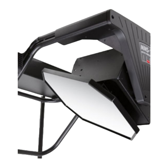
Page 13: Hardware Overview
Hardware Overview Mechanical mirror rotation (196 degrees total) in Pan direction Mechanical mirror rotation (102 degrees total) in Tilt direction Mounting system providing multiple projector options MMS200 User Guide --- (Details subject to change, and clarification) -
Page 14: Related Accessories
Related Accessories Please contact High End or your local distributor for related Accessories for the MMS200. Mounting Kits for other projectors Replacement safety cable kits DMX and Ethernet cabling for professional installations. MMS200 User Guide --- (Details subject to change, and clarification) -
Page 15: Setup And Configuration
Setup and Configuration This section contains detailed information about the fixture, including Hardware Components, Hardware setup, Connection Ports and Mounting instructions. MMS200 User Guide --- (Details subject to change, and clarification) - Page 16 Unpacking the MMS 200 The MMS200 ships in a package specifically designed to protect the product during transport. When unpacking, inspect both the outside of the fixture and the outside of the package for damage. If there is significant physical damage to the exterior package, it is advised to not accept delivery and/or...
-
Page 17: Hardware Components
Hardware Components The MMS200 contains various components not found in conventional robotic fixtures. These include: 1. Moving Mirror Assembly 2. Skeleton Mounting frame 3. Electronics Housing MMS200 User Guide --- (Details subject to change, and clarification) -
Page 18: Hardware Setup
Hardware Setup The MMS200 comes fully assembled from the factory. Depending on the specific projector, you may need to: Adjust Projector Frame mounting options Adjust DMX start channel Connect to DMX network for control from a lighting console. MMS200 User Guide --- (Details subject to change, and clarification) -
Page 19: Connection Ports
Connection Ports Connection ports on the MMS200 allow for control flexibility and system design flexibility. At times, all ports may not be used. Connection ports: 5-pin DMX Data In and Data Out Pan / Tilt Motor harness connector DO NOT UNPLUG MOTOR HARNESS WHILE POWERED, SERIOUS ELECTRONIC DAMAGE WILL OCCUR) - Page 20 CAUTION: Always isolate MMS200 fixtures from generators with a UPS or good quality power conditioner to prevent dam- age. Specific damage can occur due to generator drop-outs, sharp voltage and frequency fluctuations. MMS200 User Guide --- (Details subject to change, and clarification)
- Page 21 MMS200 Mirror Head Homing When the MMS200 fixture is connected to an appropriately-rated power source, it will automatically begin a homing procedure to verify its orientation. The mirror will move through a number of moves to determine the its precise location relative to its full range of travel.
- Page 22 Mounting the MMS200 to a Projector The alignment of the MMS200 mirror to the projector's optical path is critical for good performance. In addition, the physical attachment of the MMS200 must be correct to not cause damage to the projector nor the fixture nor cause bodily harm.
- Page 23 Mounting to a Barco FLM (Un-mounted, Clamps open) Mounting to a Barco FLM - (Mounted, Clamps closed) MMS200 User Guide --- (Details subject to change, and clarification)
- Page 24 Mounting to a Barco HDX (Un-mounted, Clamps open) MMS200 User Guide --- (Details subject to change, and clarification)
- Page 25 Mounting to a Barco HDQ (Un-mounted, Clamps open) MMS200 User Guide --- (Details subject to change, and clarification)
- Page 26 Side Mounting to a Barco 2k40 (Un-mounted, Clamps open) MMS200 User Guide --- (Details subject to change, and clarification)
- Page 27 Side Mounting to a Barco HDX (Un-mounted, Clamps open) MMS200 User Guide --- (Details subject to change, and clarification)
- Page 28 MMS200 - DMX Link The MMS200 can be used with a standard DMX512 link for control by a DMX desk. The number of fixtures you can connect to a DMX link are determ- ined by the combined number of channels required by the all the fixtures on the link. The numbers of required channels per MMS200 is (DMX footprint size)
-
Page 29: Fixture Setup
Fixture Setup This section contains detailed information about configuration options. MMS200 User Guide --- (Details subject to change, and clarification) - Page 30 Configuration Options - MMS200 Before programming a MMS200 fixture from a DMX512 console, configure the fixture by: Attaching the DMX source to the fixture. Connecting to a proper power source. Assigning a valid Start Channel (the first DMX channel designated by the console for this fixture).
- Page 31 Menu System Setup - MMS200 Using the Menu System on the MMS200 will allow all basic configuration setting to be made from the LED screen. All Menu navigation is completed by using the Directional button, the Select Button, and Enter Button located on the front panel.
- Page 32 Select the MMS200 on the control console, adjust the pan and tilt parameters as desired. NOTE: If you have trouble seeing mirror movement and you are not using a lighting console from High End Systems, check that the library for your desk has the correct default settings for all DMX channels.
-
Page 33: Verifying Operation
Note that the Mirror will start and complete the homing routine. Upon completion, the motion system, motion position, and menu system are known to be working. To verify that DMX values are being received by the MMS200 Ensure that there is a DMX source connected and sending data. - Page 34 MMS200 Shutdown The shutdown of the MMS200 fixture requires no careful consideration, however take note of the shutdown procedure of the attached projector. Pro- jection lamp life can be greatly shorten if a proper shutdown procedure is not followed. MMS200 User Guide --- (Details subject to change, and clarification)
-
Page 35: Menu System
Menu System This section contains detailed information describing the menu system and menu system layout. MMS200 User Guide --- (Details subject to change, and clarification) - Page 36 MMS200 Menu Display The MMS200 display panel gives access to the fixture’s on board menu system. Please see the Menu System Section for detailed descriptions of func- tionality. MMS200 - Menu Display MMS200 User Guide --- (Details subject to change, and clarification)
-
Page 37: Lcd Menu Navigation
Press <Enter> to edit an item. This item will flash. Press <UP>/ <DOWN> to cycle through available options. Press <Enter> to store the edited value. This item will turn solid. Press <Menu>to cancel an edit. MMS200 User Guide --- (Details subject to change, and clarification) - Page 38 Software Version Number UNIQ Unique ID Number F/HR Total Fixture hours 1-512 Shows incoming DMX Value for selected Ch. M/VR MOTR Shows Motor HW. SW. Version DISP Show LED HW. SW. Version MMS200 User Guide --- (Details subject to change, and clarification)
- Page 39 2. Scroll to the SET menu. Press <Enter> to select. 3. Scroll to the FACT menu press <Enter>. 4. Scroll to ON to restore the factory option defaults. 5. Press <Enter> to store. MMS200 User Guide --- (Details subject to change, and clarification)
- Page 40 2. Scroll to the SET menu. Press <Enter> to select. 3. Scroll to the T/in menu press <Enter>. 4. Scroll to ON to invert the pan motion, or OFF for normal operation. 5. Press <Enter> to store. MMS200 User Guide --- (Details subject to change, and clarification)
- Page 41 Mode Menu (MODE) ---> Firmware Cross Load (XLD) The MMS200 fixture can crossload software from one fixture to additional MMS200 fixtures on the same DMX link. To Cross Load Software: 1. Disconnect the data cable between the console and the first fixture 2.
- Page 42 ---> Accept new Boot Code (BOOT) When the MMS200 fixture is uploaded, occasionally it is necessary to include a new boot code with the latest software. This is apparent when bOOT dIff appears in the display. You must accept and store the new boot code: To accept the new Boot Code for the fixture: 1.
- Page 43 4. Software versions will be displayed on screen Information Menu (INFO) ---> Unique ID Number (UNIQ) Used this menu item to view the unique ID number of the MMS200 fixture. To view Unique ID number: 1. Press and hold <Menu> until AddR appears on the LED display.
- Page 44 Information Menu (INFO) ---> DMX Data (DMX) This procedure allows you to use a MMS200 fixture to view DMX channel values all devices on the DMX link. Use this menu option to: Checking current DMX values on this fixture Test devices that do not have built-in DMX diagnostics Check fixtures that are physically inconvenient to monitor directly To view DMX data:...
-
Page 45: Motion System
Motion System This section contains detailed information surrounding the motion system of the MMS200. MMS200 User Guide --- (Details subject to change, and clarification) - Page 46 Note: The MMS200 fixture uses optical encoders for pan and tilt to correct the mirror position if the mirror is held or jarred from its pro- grammed position. If a physical obstruction prevents the mirror from correcting its position, this correction feature will time-out to prevent other damage.
- Page 47 0.17 0.19 0.21 0.25 0.29 0.35 0.41 0.47 0.55 0.63 0.73 0.83 0.94 1.05 1.18 1.31 1.45 1.60 1.75 1.92 2.09 2.27 2.46 2.66 2.86 3.07 3.29 3.52 3.76 4.00 MMS200 User Guide --- (Details subject to change, and clarification)
- Page 48 10.17 10.58 10.99 11.41 11.84 12.28 12.72 13.17 13.63 14.10 14.58 15.07 15.56 16.06 16.57 17.09 17.61 18.14 18.68 19.23 19.79 20.36 20.93 21.51 22.10 22.70 23.30 23.92 24.54 25.17 MMS200 User Guide --- (Details subject to change, and clarification)
- Page 49 38.65 39.44 39.44 40.23 41.04 41.85 42.68 43.50 44.34 45.19 46.04 46.90 47.77 48.65 49.54 50.43 51.33 52.24 53.16 54.09 55.02 55.96 56.91 57.87 58.84 59.81 60.79 61.78 62.78 63.79 MMS200 User Guide --- (Details subject to change, and clarification)
- Page 50 84.43 85.59 86.77 87.95 89.14 90.34 91.55 92.76 93.98 95.21 96.45 97.70 98.95 100.22 101.49 102.77 104.05 105.35 106.65 107.96 109.28 110.61 111.94 113.28 114.63 115.99 117.36 118.73 120.12 121.5v MMS200 User Guide --- (Details subject to change, and clarification)
- Page 51 152.57 154.14 155.71 157.30 158.89 160.49 162.09 163.71 165.33 166.96 168.60 170.25 171.91 173.57 175.24 176.92 178.61 180.30 182.01 183.72 185.44 187.17 188.90 190.65 192.40 194.16 195.92 197.70 199.48 201.28 MMS200 User Guide --- (Details subject to change, and clarification)
- Page 52 203.08 204.88 206.70 208.52 210.36 212.19 214.04 215.90 217.76 219.63 221.51 223.40 225.30 227.20 229.11 231.03 232.96 234.90 236.84 238.79 240.75 242.72 244.70 246.68 248.68 250.68 246.68 248.68 250.68 252.68 MMS200 User Guide --- (Details subject to change, and clarification)
- Page 53 Mirror Position - Fine Correction The MMS200 motion system allows for the 2 positional modes, Fine Correction Enabled, Fine Correction Disabled. By default Fine Correction is dis- abled, due to the behavior that the mirror makes a small correction update at the end of travel - this can be seen as an error without fully under- standing the system.
- Page 54 This page intentionally left blank to ensure new chapters start on right (odd number) pages. MMS200 User Guide --- (Details subject to change, and clarification)
- Page 55 Appendix This section contains general and detailed information surround various aspects that can be incorporated with the MMS200 fixture. MMS200 User Guide --- (Details subject to change, and clarification)
-
Page 56: Attaching A Power Cord Cap
The fixture ships with an SJT power cord. Use the information in this section to replace the power cord cap for locations with another electrical stand- ard. Because of the variety of power cord caps used worldwide, High End Systems, Inc. cannot make specific recommendations for the power cord cap. - Page 57 The number in parenthesis indicates the number of consecutive times the value must be received from the DMX con- Number (x) troller before the indicated function is actuated. The dimmer, slot 5, is required to be closed during this time, DMX = MMS200 User Guide --- (Details subject to change, and clarification)
-
Page 58: Control Card Replacement
Control Card Replacement There is one control card in the MMS200. To replace these you will need to open the electronics box, unplug all connections to the boards and un- mount the card. Opening the Electronics housing You will need to open the electronics housing, this is the box that contains the LED screen and the menu buttons Remove all screws that secure the lid to the chassis. - Page 59 The DMX Card will need to be removed to gain access to the bezel screws. Remove the 4 screws that contain the DMX card. Once the card is free, there is no need to disconnect the wiring harness. MMS200 User Guide --- (Details subject to change, and clarification)
- Page 60 Remove the Bezel Screw (picture shown with DMX card in the way, this must be removed to gain access to the top, rear screw) MMS200 User Guide --- (Details subject to change, and clarification)
- Page 61 Be sure to note all wiring connections. Check that the wiring harness is labeled, and matches the labels on the board before removing. Remove the connectors carefully. The Control card should be free. Set aside, touching only the edges, and placing on a static free surface. MMS200 User Guide --- (Details subject to change, and clarification)
- Page 62 Attach the Bezel with 4 screw Install the DMX Daughter Card with 4 screws Close lid, note wire routing and wire pinch points Attach all screws, visually inspect and ensure all components are securely attached. MMS200 User Guide --- (Details subject to change, and clarification)
-
Page 63: Mechanical Specifications
Weight: 23.1 kg (51 lbs) Shipping Pallet Dimensions: 711mm x 737 mm x 1168mm ( 28in x 29 in x 46 in) Weight (Fixture + Shipping Pallet): 41.7kg (92 lbs) Left ISO View MMS200 User Guide --- (Details subject to change, and clarification) - Page 64 Top ISO View MMS200 User Guide --- (Details subject to change, and clarification)
- Page 65 Bottom ISO View MMS200 User Guide --- (Details subject to change, and clarification)
- Page 66 Mounting Frame Footprint MMS200 User Guide --- (Details subject to change, and clarification)
- Page 67 Pan Travel (MMS100 Shown, Travel is Identical) MMS200 User Guide --- (Details subject to change, and clarification)
- Page 68 Tilt Travel (MMS100 Shown, Travel Identical) MMS200 User Guide --- (Details subject to change, and clarification)
- Page 69 Software Upload using Echo The internal software for the MMS200 can be upgraded remotely via DMX using the Echo application and a USB DMX widget or an Upload module. Below is the outline for the uploading procedure Software update procedure Be sure the DMX Widget or Upload module has correct drivers installed, contact support if assistance is needed Connect the MMS200 via DMX to the Upload Module or DMX widget...
- Page 70 The MMS200 can be controlled via the Barco Projector Tool-Sets application. This integration allows the projector control software to output a DMX signal to move the attached MMS200 mirror. The specifics of outputting DMX from the front 4 Pin connector on a Barco Projector varies per model, please see specific documentation for you projector or contact Barco support.
Need help?
Do you have a question about the MMS200 and is the answer not in the manual?
Questions and answers