
Related Manuals for ClearOne Beamforming Microphone Array


Summary of Contents for ClearOne Beamforming Microphone Array
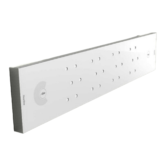
- Page 1 Beamforming Microphone Array Group Microphone for Professional Conferencing nstallatIon uIde...
- Page 2 DOC-0095-001 Rev 3.1 - December, 2014 © 2014 ClearOne All rights reserved. No part of this document may be reproduced in any form or by any means without written permission from ClearOne. Printed in the United States of America. ClearOne reserves specific privileges.
-
Page 3: Table Of Contents
Table of Contents Chapter 1: Getting Started ......................1 SKU’s Used ..................................1 Connections ..................................2 Powering the Beamforming Microphone Array ......................2 E-bus Connections ..............................2 Chapter 2: Ceiling Mount Installation ..................5 Parts Received...................................5 Tools Required ...................................6 Mounting Preparations ..............................7 Mounting to a Solid Ceiling or Flush Mounted Junction Box ....................8 Mounting to a Suspended Ceiling ...........................12... -
Page 5: Chapter 1: Getting Started
Beamforming Microphone Array Quick-Start Guide which is found on the ClearOne website at: http://www.clearone.com/resources#professional_microphones This guide covers the steps followed to mount the Beamforming Microphone Array in a solid ceiling, drop-ceiling and wall mount. This guide can also be downloaded from the ClearOne website at: http://www.clearone.com/resources#professional_microphones SKU’S USED... -
Page 6: Connections
NOTE: The PoE connection is only for power, not control. Power must be supplied to individual units; no daisy-chain power is allowed. onnections The Beamforming Microphone Array units are connected to the CONVERGE Pro stack via the LINK IN and LINK OUT E-bus connections using CAT5E RJ45 cables. »... - Page 7 CONVERGE Pro unit (LINK IN and LINK OUT). The Beamforming Microphone Array is connected to the CONVERGE Pro and to other Beamforming Microphone Array units via the E-bus in the same way as multiple CONVERGE Pro units are connected together.
- Page 8 Beamforming Microphone Array...
-
Page 9: Chapter 2: Ceiling Mount Installation
Once you have verified all the firmware updates and necessary connections made while executing the tasks outlined in the Beamforming Microphone Array Quick-Start Guide, you can proceed to the actual installation of the Beamforming Microphone Array using the Ceiling Mounting Kit. -
Page 10: Tools Required
TOOLS REQUIRED The following tools are required for installation of the Beamforming Microphone Array. Razor knife for cutting hole in suspended Drywall saw for cutting ceiling tile. hole in solid ceiling, #1 Phillips screwdriver. Electric or portable drill Drill bits... -
Page 11: Mounting Preparations
MOUNTING PREPARATIONS Use the following cutout dimensions for the type of mounting: SOLID OR SUSPENDED SOLID OR SUSPENDED CEILING CUT-OUT CEILING CUT-OUT 1-1/2” 1-1/2” (38.1mm) (38.1mm) 4" 4" (101.6mm) (101.6mm) SQUARE JUNCTION BOX CUT-OUT SQUARE JUNCTION BOX CUT-OUT CIRCULAR CIRCULAR SOLID OR SUSPENDED SOLID OR SUSPENDED CEILING CUT-OUT... -
Page 12: Mounting To A Solid Ceiling Or Flush Mounted Junction Box
The following diagram shows how to assemble the parts needed for a suspended mounting of the Beamforming Microphone Array from either a solid ceiling or from a securely fastened junction box. The junction box can be flush to either a solid ceiling or exposed through and flush to an opening in a suspended ceiling. - Page 13 Feed the LINK IN, LINK OUT and PoE cables (not shown) down through the assembly, then attach the assembly to the solid ceiling or junction box as shown in the following diagrams. Cutout through Feed the LINK IN, LINK OUT and PoE cables Soilid Ceiling down through the Suspension Column Attach the Ceiling/Wall...
- Page 14 There are three slotted keyholes big enough for screw heads to pass through and one hole that is not slotted. Partially insert screws into the Beamforming Microphone Array corresponding to the slotted keyholes in the Mic Mounting Plate.
- Page 15 Plate onto the Beamforming Microphone Array over the screws and through the keyhole slots. Then fasten the Beamforming Microphone Array securely in place with the last screw. Tighten all remaining screws. Plug in and secure the cables under the cable retention clips.
-
Page 16: Mounting To A Suspended Ceiling
The Trim Plate slips up from underneath the ceiling tile up the Suspension Column, then attaches to the Ceiling Trim Lock Plate through the ceiling tile. Suspended Ceiling Trim Lock Plate Pass-through Cutout in Ceiling Tile Trim Plate Underneath Ceiling Tile Beamforming Microphone Array... - Page 17 The Mic Mounting Plate attaches to the bottom of the Suspension Column. » NOTE: The Mic Mounting Plate can be rotated 90-degrees and then attached for applications where the microphone orientation is rotated from the mounting of the Suspension Column. Use #1 Phillips screwdriver bit HB 4X...
- Page 18 Mounting Plate below the tile. Attach the Position Clamps against the wide sides of the Suspension Column above the ceiling tile. Allow the assembled position clamps to be loose enough to slide up and down for positioning. E 2X Beamforming Microphone Array...
- Page 19 NOTE: The support rails are only long enough to span 2’ suspensions. If that orientation does not orient the Beamforming Microphone Array in the correct axis for your room, you may need to rotate the Mic Mounting plate 90 degrees to orient it correctly.
- Page 20 Slide the Suspension Column up or down adjusting it so the Beamforming Microphone Array will be placed approximately 8 feet above the floor. Fully tighten the screws on the position clamps. Attach and tighten a Locking Plate on to each Position Clamp to secure the assembly to the Support Rails.
- Page 21 HD 3X NOTE: Insert screws only partially. Slide the Beamforming Microphone Array onto the Mic Mounting Plate with the screws passing through the slotted keyholes. Insert the final holding-screw through the Mic Mounting Plate into the Beamforming Microphone Array. Tighten all screws. Plug in and route the cables through the cable slots and secure them under the Cable Retention Clips provided with the Beamforming Microphone Array.
-
Page 22: Additional Safety
The installer is responsible to be sure the Beamforming Microphone Array is firmly secured so that it does not fall. Safety cables (not provided) can be secured to the building structure then be attached to the corner holes of the Ceiling Plate to prevent the Beamforming Microphone Array from falling in case of accident or earthquake. -
Page 23: Chapter 3: Wall Mount Installation
Once you have verified all the firmware updates and necessary connections made while executing the tasks outlined in the Beamforming Microphone Array Quick-Start Guide, you can proceed to the actual installation of the Beamforming Microphone Array using the Wall Mounting Kit. -
Page 24: Wall Mounting Procedure
The Ceiling/Wall Mounting Plate is designed with small studs projecting from the plate which fit into slotted holes on the Mic Mounting Plate to hold the Beamforming Microphone Array to the wall. Slotted holes in... - Page 25 Locate, level and mark for drill holes and the cable pass-through cut-out where the Wall Mounting Plate will attach to the wall. Drill holes in the marked locations to receive the fasteners Cut out the cable pass-through cut-out hole. NOTE: The anchors and screws used to mount the Ceiling/Wall Mounting Plate »...
- Page 26 Place the Mic Mounting Plate on the back of the Beamforming Microphone Array and insert the screws (A) into the Beamforming Microphone Array corresponding to the holes in the Mic Mounting Plate.
- Page 27 For mountings with the cables coming in front of the wall, hold the Beamforming Microphone Array with the Mic Mounting Plate attached, route PoE cable under the Mic Mounting Plate and the LINK IN and LINK OUT (if needed) cables to the ends where they will be connected. Connect the LINK IN, LINK OUT and PoE cables and secure the cables under the Cable Retention Clips as shown below.
-
Page 28: Muting
(Beamforming Microphone Array and cables not shown.) Wall Mounting Plate stud through slotted kehole in Mic Mounting Plate When the wall mounting of the Beamforming Microphone Array is completed, use the CONVERGE Console software to configure the array for the proper pickup pattern. »... -
Page 29: Chapter 4: Table Top Installation
Once you have verified all the firmware updates and necessary connections made while executing the tasks outlined in the Beamforming Microphone Array Quick-Start Guide, you can proceed to the installing the Beamforming Microphone Array on a table top in your conference room. There is no installation kit required. -
Page 30: Usage
When the table top installation of the Beamforming Microphone Array is completed, use the CONVERGE Console software to configure the array for the proper pickup pattern. uting On the tabletop, the Mute On/Off buttons are readily available for use when conferencing. When the microphone array is active, the microphone icons in the buttons illuminate blue. -
Page 31: Chapter 5: Change History
Chapter 5: Change History This is the third revision of the Beamforming Microphone Array Installation Guide. It incorporates design changes to the Ceiling/Wall Mounting Plate, the Trim Plate, and Mic Mounting Plate allowing for a more secure installation, including the new feature of mounting to a junction box and a more secure trim plate attachment. -
Page 32: Service And Support
Sales: +800.707.6994 Fax: +801.303.5711 e-mail: sales@clearone.com © 2014 ClearOne. All rights reserved. Other product names may be trademarks of their respective owners. Specifications subject to change without notice. DOC-0095-001 Rev. 3.1 - December, 2014. Beamforming Microphone Array...
Need help?
Do you have a question about the Beamforming Microphone Array and is the answer not in the manual?
Questions and answers