
Related Manuals for ClearOne Beamforming


Summary of Contents for ClearOne Beamforming
- Page 1 Beamforming Microphone Array Systems Group Microphone for Professional Conferencing Wall Mount Installation Guide...
-
Page 2: Table Of Contents
Table of Contents GETTING STARTED ................1 SKUs USED ..................2 CONNECTIONS .................3 ......3 owering your eamforming icroPhone rray yStem .................4 onnectionS & P-L ..............4 onnectionS WALL MOUNT INSTALLATION ............6 ..................6 artS eceived ..................7 ooLS equired ..............7 ounting rocedure ....................15 uting... -
Page 3: Getting Started
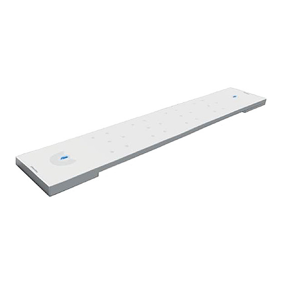
WALL MOUNT INSTALLATION GUIDE GETTING STARTED Congratulations on purchasing your Beamforming Microphone Array (BFM) product. BFM units feature 24 microphones with beamforming and adaptive steering technology designed specifically for use with the CONVERGE Pro or CONVERGE Pro 2 systems. ®... -
Page 4: Skus Used
BEAMFORMING MICROPHONE ARRAY SYSTEMS SKUs USED The following assemblies or kits may be used in the BFM installation: • 910-001-003 (white) or 910-001-003-B (black) BFM1 • 910-3200-201 (white) or 910-3200-201-B (black) BFM2 • 910-001-004 PoE Power Supply and Cable Kit for BFM1. Contains power supply, one AC power cable and two 25-foot CAT5E RJ45 Plenum cables. -
Page 5: Connections
Powering a BFM System Both the BFM1 and BFM2 can be powered by a standard PoE switch or a PoE power supply (external or ClearOne; up to three BFM2 units can be powered by one ClearOne PoE Injector). Additionally, the BFM2 can be powered via a P-Link from CONVERGE Pro 2 (a single cable carries power, audio and control). -
Page 6: P O E C Onnections
NOTE: The PoE connection is only for power, not control. There is no daisy-chain power for the BFM1, power must be supplied to individual units. For the BFM2, power only needs to be supplied to individual units if not using a ClearOne or same specification standard PoE Injector. ink and... - Page 7 WALL MOUNT INSTALLATION GUIDE BFM1 units are connected to a CONVERGE Pro stack via LINK IN and LINK OUT E-bus connections using CAT5E RJ45 cables. BFM2 units are connected to a CONVERGE Pro 2 stack via P-Link In and P-Link Out connections using CAT5E or CAT6 RJ45 cables. power-source-selection switch Wall Mount Installation Guide...
-
Page 8: Wall Mount Installation
BEAMFORMING MICROPHONE ARRAY SYSTEMS The BFM1 is connected to the CONVERGE Pro and to other BFM1 units via the E-bus in the same way multiple CONVERGE Pro units are connected together. Each unit has a LINK IN and LINK OUT E-bus connection that allows units to be “chained”... -
Page 9: Tools Required
The following tools may be required for Wall Mount installation of the Beamforming Microphone Array. You will also need other tools for installing fasteners (not included in the kit) to hold the Wall Mounting Plate to the wall where the Beamforming Microphone Array is to be installed.) #1 Phillips... - Page 10 BEAMFORMING MICROPHONE ARRAY SYSTEMS level with the participants. The face of the BFM should be about 8 to 10 feet from the participants. The Wall Mounting Plate has small studs projecting from the plate that fit into slotted holes on the Mic Mounting Plate to hold the BFM to the wall.
- Page 11 WALL MOUNT INSTALLATION GUIDE Hollow wall mounting gives the advantage of concealed cable routing. Locate, level and mark for drill holes and the cable pass-through cut-out where the Wall Mounting Plate will attach to the wall. Use the following dimensions for the cable pass-through cut-out for a hollow wall mounting: WALL MOUNT CUT-OUT...
- Page 12 BEAMFORMING MICROPHONE ARRAY SYSTEMS Wall fasteners not included in the kit. Select fasteners appropriate to wall material. Attach the Wall Mounting Plate to the wall with fasteners. If you have attached the Wall Mounting Plate to a hollow wall, thread the cables for Link In, Link Out and PoE through the wall space and out through the hole in the center of the plate.
- Page 13 WALL MOUNT INSTALLATION GUIDE Notice that the Mic Mounting Plate (C) has four holes used for mounting to the back of the Beamforming Microphone Array. There are three slotted keyholes big enough for screw heads to pass through and one hole that is not slotted.
- Page 14 Ceiling/Wall Mounting Plate For mountings with the cables coming through the wall, hold the Beamforming Microphone Array with the Mic Mounting Plate attached, route the E-bus and PoE cables under the Mic Mounting Plate to the ends where they will be connected. Connect the LINK IN, LINK OUT (if needed) and PoE cables and secure the cables under the Cable Retention Clips.
- Page 15 Carefully route cables to the mixer to avoid tangling or hazard. Move the Beamforming Microphone Array forward onto the Wall Mounting Plate with the studs passing through the slotted keyholes. Then slide the assembly down slightly to firmly seat the studs into the tops of the slots.
- Page 16 (Beamforming Microphone Array and cables not shown) Wall Mounting Plate stud through slotted keyhole in Mic Mounting Plate When the Wall mounting of the Beamforming Microphone Array is completed, use the CONVERGE Console software to configure the array for the proper pickup pattern.
-
Page 17: Muting
When the microphone array is active, the microphone icons in the buttons illuminate blue. If either button is pressed, the Beamforming Microphone Array mutes and the buttons illuminate red. If pressed again, the array un-mutes and is active again. - Page 18 Tel: +44.1454.616.977 Tel: +91.9930782195 e-mail: global@clearone.com e-mail: global@clearone.com Middle East: Tel: +91.9930782195 e-mail: global@clearone.com © 2016 ClearOne, Inc. All rights reserved. Information in this document is subject to change without notice. DOC-0139-001 Revision 2.2 SEPTEMBER 2016 Beamforming Microphone Array Systems...
Need help?
Do you have a question about the Beamforming and is the answer not in the manual?
Questions and answers